1
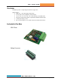
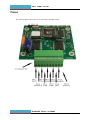
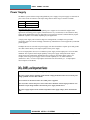
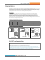
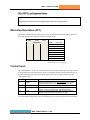
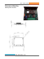
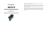
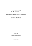
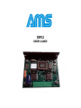
DRV2 USERS GUIDE Overview ....................................................................................................................................................... 3 Included in the Box: ....................................................................................................................................... 3 Pinout ............................................................................................................................................................ 4 Installation ..................................................................................................................................................... 5 Power Supply ................................................................................................................................................ 6 Stepping Motors ............................................................................................................................................ 7 DIP Switch (JP1) Location ............................................................................................................................ 8 Setting the Output Current (JP1) .................................................................................................................. 8 Microstep Resolution (JP1) ........................................................................................................................... 9 Control Input .................................................................................................................................................. 9 Electrical Specifications .............................................................................................................................. 10 Thermal Specifications ................................................................................................................................ 10 Dimensions & Mounting .............................................................................................................................. 11 Design Tips ................................................................................................................................................. 12 Optional Heat Sink ...................................................................................................................................... 11 Contact AMS ............................................................................................................................................... 12 ADVANCED MICRO SYSTEMS P age | 2 DRV2 USERS GUIDE Overview The DRV2 provides a compact high resolution 2A stepper drive. DRV2 Features: Single 12V – 40V input supply voltage range 0 to 2A phase current, adjustable via DIP switches 1/2, 1/4, 1/8, 1/16, 1/32, 1/64, 1/128, 1/256 microstep, set by DIP switch Electrically-isolated and optically-coupled STEP, DIR & ENABLE inputs Control input voltage: 5-25V Easy wire-up using the screw terminal connectors included with the drive Included in the Box DRV2 Drive: Mating Connector: WWW.STEPCONTROL.COM P age | 3 DRV2 USERS GUIDE Pinout The following diagram shows the pins for connecting to the DRV2 board: ADVANCED MICRO SYSTEMS P age | 4 DRV2 USERS GUIDE Installation The following installation procedure outlines the minimum steps required to make the DRV2 operational: 1. Connect a 12VDC to 40VDC power supply to connector J1 (see diagram). Pin 1 needs to be connected to Ground and Pin 2 to the positive voltage (VSUPPLY). See section “Power Supply” for type and sizing of recommended power supply. 2. With the power off connect a motor to pins 3, 4, 5,and 6 of J1 (see diagram). Typical motor connection diagrams are shown in the Stepping Motors section of this manual. Be sure to insulate all motor leads and unused leads (in the case of a 6-lead motor) to prevent shorts to ground, or to each other. 3. Set the desired motor drive current value using the DIP Switches (JP1). See Section Setting the Output Current for more information. 4. Wire STEP, DIRECTION, and driver ENABLE signals as well as the positive reference voltage level of the signals (VIN+) to connector J1. See section “Control Input” of this manual for more details. 5. Set the microstep resolution using the DIP switches. See Section Microstep Resolution for more information. 6. Apply power to the DRV2. Do not connect or disconnect the motor when power is ON. The power supply voltage, including ripple and line voltage fluctuations, must not exceed 40VDC or be less than 12VDC. Make sure the motor to be used is compatible with the drive. WWW.STEPCONTROL.COM P age | 5 DRV2 USERS GUIDE Power Supply The DRV2 is powered from a single unregulated DC power supply. The power supply is connected via pins 1 and 2 of the J1 Connector. The input voltage must be in the range of 12VDC to 40VDC. Pin 1 2 Function Ground High voltage Recommended Power Supply Circuit In general, unregulated DC (or linear regulated) power supplies are best suited for stepper motor applications. Switching power supplies, which tend to be very cost efficient, are also suited for many stepper motor applications; however, their ability to provide surge currents is limited and may require additional capacitors to be added, depending on your application. A single power supply can be used for single axis configurations, or multiple axes, provided component values are scaled accordingly. Alternatively, individual axes can be supported by individual power supplies. If multiple drivers are used with one power supply, each drive should have separate power and ground wires that connect directly to the output capacitor of the power supply. For 2A of output phase current, we recommend a power supply with an output power of 35-40 Watts minimum. The required current output capability of the power supply will depend on the output voltage and can be calculated by dividing the above wattage by the output supply voltage. For example, when using a power supply of 24V a current capability of 1.7A will be sufficient (40W/24V=1.66A). For lower output phase current this rule scales linearly (i.e. 1A output phase current requires 18-20 Watts). Individual axes should be independently fused for fault isolation. The power supply voltage, including ripple and line voltage fluctuations must not exceed the peak rating of 40VDC or be less than 12VDC. Do not connect or disconnect motor wires while power is applied. Wire size used to connect the power source to the driver should be at least 18 gauge. Heavier wire should be used for longer distances between the power supply and the driver. The power supply output current needed is dependent on the supply voltage, motor selection and load. ADVANCED MICRO SYSTEMS P age | 6 DRV2 USERS GUIDE Stepping Motors The DRV2 is a bipolar, chopper driver that works with both bipolar and unipolar motors, i.e. 8-, 4- and 6-lead motors. It is also possible to drive half of a 6-lead center tapped motor with the DRV2, however the performance may be compromised. To avoid unstable chopping conditions and to provide a higher speed-performance ratio, a motor with low winding inductance is preferred. Drive Current The ideal current for a given motor is based on the specific characteristics of the motor and the requirements of the application. As a result, establishing the correct current is often determined empirically. Insufficient current will result in inadequate torque and under utilization of the motor. Excessive current can cause high-speed torque ripple, resulting in stalling or pole slippage, over heating of the motor and general inefficiency of the system. Current setting procedures are described in the next section; “Setting The Output Current” Connecting a Stepping Motor (J1 pins 3-6) Pin # Description Function 3, 4 5, 6 1A, 1B 2A, 2B Phase 1 of the Stepping Motor is connected between pin 3 and 4 of J1. Phase 2 of the Stepping Motor is connected between pin 5 and 6 of J1. Typical 4, 6 and 8 lead motor configurations 1B 1B 1 1 5 5 2 2 1A 6 1A 6 2B 8 4-Wire Parallel 2B 4 2A 7 2A 3 6-Wire Motor 3 7 4 8 A Basic 8-Wire Motor Do not connect or disconnect motor wires while power is supplied When using a 6-lead motor be sure to insulate/isolate unused wires. The physical direction of the motor with respect to the logical direction input will depend on the connection of the motor windings. To reverse the direction of the motor with respect to the direction input, switch the wires on one phase (either phase 1 or phase 2) of the outputs. WWW.STEPCONTROL.COM P age | 7 DRV2 USERS GUIDE DIP Switch (JP1) Location The following picture shows the DIP Switch (JP1) location on the DRV2 board: Setting the Output Current (JP1) The phase current is set using DIP switches SW1 - SW6. Switches SW1 - SW3 set the Hold Current, and switches SW4 - SW6 set the Run Current. See below for the settings: SW1 OFF ON OFF ON OFF ON OFF ON SW2 Hold Current OFF OFF ON ON OFF OFF ON ON SW3 OFF OFF OFF OFF ON ON ON ON SW4 OFF ON OFF ON OFF ON OFF ON SW5 SW6 Run Current OFF OFF OFF OFF ON OFF ON OFF OFF ON OFF ON ON ON ON ON Value 0A 0.3A 0.7A 1.0A 1.3A** 1.7A 2.0A 2.0A Power-down the drive prior to changing current settings. The actual motor current will vary based on a number of factors including motor characteristics, cable length, and shielding. The rule of thumb is to set the output current where reliable motion is achieved, but without excessive motor heating. **Current is factory preset to 1.3A. ADVANCED MICRO SYSTEMS P age | 8 DRV2 USERS GUIDE Apply minimal force when adjusting the switches or risk damaging them. Using low power values may cause a slight change in the motor resting position. Microstep Resolution (JP1) The number of microsteps per full step is selected by the three DIP switches according to the below table. Note that the ‘ON’ position is labeled on the DIP switch. SW7 SW8 Resolution OFF OFF ON ON OFF OFF ON ON OFF ON OFF ON OFF ON OFF ON SW9 OFF OFF OFF OFF ON ON ON ON Value 1/2** 1/4 1/8 1/16 1/32 1/64 1/128 1/256 Steps/ Rev. 400 800 1600 3200 6400 12800 25600 51200 **Factory preset to ½ stepping. Control Input The control inputs are wired to J1. To create motor motion at least the STEP and VIN+ inputs need to be wired and driven. Note, that since the inputs are electrically isolated from the internal circuitry of the DRV2, the high level voltage of the input signals needs to be provided as reference for the optocoupler circuitry. Pin # 7 Name STEP 8 9 DIR ENABLE 10 VIN+ Description Stepping is triggered on every falling transition of the STEP input. Minimum duration of the high and low level is 2µs. Direction signal. If unconnected a high level is assumed. If left unconnected or supplied with a high level, the drive is enabled. A low level on this input will disable the drive. High level of input signals STEP / DIR / ENABLE. This is required as reference for the optocoupler circuitry. For the allowable voltage range on the control inputs please see the section Electrical Specifications. WWW.STEPCONTROL.COM P age | 9 DRV2 USERS GUIDE Electrical Specifications Parameter Supply Voltage Run Output Current/Phase (PEAK) Min 12 0 Max 40 2.0 Unit V (DC) A Hold Output Current/Phase (PEAK) 0 2.0 A Stepping Resolution 2 256 Steps per full step Min 0 Max 500 Unit kHz 5 25 0 V (DC) mA 25 5 mA mA µs Input Signals: Signals Frequency (limited by optocoupler) High Input Voltage High Input Current Low Input Current For 24V input high level For 5V input high level Low time / high time for STEP input 2 Notes DIP Switch Selectable DIP Switch Selectable DIP Switch Selectable A step sequence is triggered with the falling edge of the Step Input. Thermal Specifications Operating Temperature…………………0 to +50 C Storage Temperature…………………. -40 to +125 C ADVANCED MICRO SYSTEMS P age | 1 0 DRV2 USERS GUIDE Dimensions & Mounting Mounting Plate / Heat Sink Heatsink and mounting diagram can be supplied by AMS - call or email for details. WWW.STEPCONTROL.COM P age | 1 1 DRV2 USERS GUIDE Design Tips EMI (electromagnetic interference or electrical noise) can be a major source of problems when integrating power drivers with microprocessor based devices. EMI is typically generated through ground loops and AC power line disturbances. External devices such as, relays, coils, solenoids, arc welders, motors, drivers, and other computer-based equipment are also sources of EMI. The following design tips will help to prevent EMI from interfering with the system operation: Shield the driver and wiring by mounting it in its own metal enclosure as far away from noise sources as possible. Ground motor shields only at the driver end. Make sure that all power wiring (motor, AC, etc.) is away from the signal wiring (I/O, communications lines, etc.). Mechanical grounds should all be tied to Earth at a single point. Chassis and motor grounds should be tied to the frame and the frame to Earth. Ground all signal wiring to one point. Use solid-state relays or opto isolators whenever possible to isolate remote signals. Suppress all mechanical relays with capacitors or MOV’s. Use shielded, twisted pair cables for the motor, I/O and communications wiring. **************** WARNING ******************** CONNECTING/DISCONNECTING MOTORS WHILE POWERED WILL CAUSE DAMAGE THAT IS NOT COVERED BY WARRANTY. Contact AMS www.stepcontrol.com Email: [email protected] Phone: 603-882-1447 Address: 3051 N. Hwy 183 - Liberty Hill, Texas 78642 Revision Date: 10/14/2014 ADVANCED MICRO SYSTEMS P age | 1 2