1
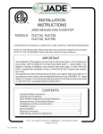
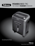
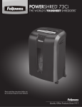
™
CSD205H
MICROSTEPPING DRIVE MODULE
USER’S MANUAL
CSIM Inc.
“Control System In Motion”
September 2002
TABLE OF CONTENTS
SECTION 1: INTRODUCTION …………………………………………
1.1
Overview ………………………………...…………
1.2
Product Features
…………………………………...
1.3
Electrical Specifications ……………………………..
2
2
2
2
SECTION 2: EXPRESS START UP PROCEDURE
…………………..
3
SECTION 3: TERMINAL LOCATIONS AND ASSIGNMENTS .......…
3.1
Motor connection …………………………………....
3.2
Power Input
………………………………………..
3.3
Control Signal Input
…………………….………..
4
4
5
5
SECTION 4: DIP SWITCH SETTINGS
…………………...…………
7
SECTION 5: OPERATION INSTRUCTION
.........................................
5.1
Motor Compatibility
…………………………...…
5.2
Supply Voltage
……………………………………
5.3
Current Setting
…………………….……………
5.4
Current Damping Function
……………..…………
5.5
Automatic Current reduction ………………..………
8
8
8
9
9
9
SECTION 6: TROUBLE SHOOTING
……..…………………………
6.1
In General
………………….………………………
6.2
Chick List
….………………………………………
10
10
10
Control System In Motion
Page 1
CSIM Inc.
SECTION 1:
1.1
INTRODUCTION
Overview
The CSD205H Microstepping Drive Module is a high performance
microstepping driver. It can provide an output current up to 6(rms) amperes
per phase to operate a step motor at 40,000 microsteps per revolution.
1.2 Product Features
z Single power supply input
z High and wide range input voltage (24 to 75Vdc)
z Switch selectable current level from 3 to 6 Amps rms (4.2 to 8.4 Amps peak)
z Switch selectable microstepping resolution from 400 to 40,000 microsteps
z
z
z
z
z
z
1.3
per revolution
Automatic idle current reduction
Optically isolated inputs
Input signals use Pulse/Direction mode or CW/CCW pulse mode is
selectable by a switch
Selectable current damping function to reduces resonant vibration and noise
at low speed
Motor clockwise or counterclockwise rotate can be swapped by a switch
All input signal terminals are equipped with convenient Snap-In head
Electrical Specifications
ITEM
Input power
Min
Typ
Max
24Vdc
65Vdc
75Vdc
Output current per phase
3 Amps RMS
4.2 Amps Peak
6 Amps RMS
8.4 Amps Peak
Microstep resolution
400
steps/revolution
40,000
steps/revolution
Maximum input pulse rate
Control System In Motion
1,000,000
pulses/sec
Page 2
CSIM Inc.
SETCTION 2: EXPRESS START UP PROCEDURE
The following instructions define the minimum procedures necessary to make the
CSD205H microstepping drive module operational.
1. Check the motor used is suitable to the CSD205H. Please refer to the section
5.1 about how to select a motor.
2. Set the correct current level for the motor as described in section 4 and section
5.3. While the current setting is more than 3 amps, heat sinking may be required
to maintain case temperature below +70°C.
3.
4.
5.
6.
7.
8.
Select the appropriate step resolution and set the switches as described in section
4.
Connect the motor following the “Motor Connections” description in section 3.1.
Connect the control input signal as described in section 3.3.
Connect the power source to the DC input terminal as described in section 3.2.
The indicate LED should turn on immediately after power on. The motor will
be locked by a holding torque.
Send the pulses signal input to driver, the motor should rotate according to the
pulse rate and the step resolution set.
If the motor’s rotation direction is improperly, swap the dip switch #4 as
description in section4 will change it.
Caution:
Always disconnect the power to the module before connecting or disconnecting the
motor leads. Failure to do this will result in a shock and may damage the driver.
Control System In Motion
Page 3
CSIM Inc.
SECTION 3:
3.1
TERMINAL LOCATIONS AND ASSIGNMENTS
Motor Connection
The motor connections are made via the 4-terminal Head JP2.
Table 3.1
JP2 Pin
4
Assignment
Phase B-
3
Phase B+
2
Phase A-
1
Phase A+
The CSD205H is a Bipolar driver. It could work equally well with both
Bipolar motors, i.e. 4 and 8 lead motors and Unipolar motors, i.e. 6 lead center
tapped motors.
Figure 3.1 Motor connection
Control System In Motion
Page 4
CSIM Inc.
3.2
Power Input
The DC input power is connected to head JP1. Please be aware that pin+ is the
power supply plus(+) connection and pin- is the power supply minus(-)
connection. Connecting the pins incorrectly will not damage the CSD205H
because of the built-in protect circuit, but the CSD205H will not operate. An
unregulated power supply coupled with a filter capacitor is preferable. A
switching regulated power supply may not be suitable for use with the
CSD205H. Please refer to section5.2 about the supply voltage.
3.3 CONTROL SIGNAL INPUT
The control signal input is made via the 4-terminal Head JP3.
Table 3.2
JP3 Pin
Pin Name
Function Description
1
OPTO
This terminal should be connected to +5Vdc supplied power
for the opto-isolators.
2
Pulse/CW
In pulse mode
(SW #8 On)
A high to low transition on this
terminal will advances the motor one
step. The direction is determined by Pin
3 state.
In CW/CCW mode A high to low transition on this
(SW #8 Off)
terminal will advance the motor one
step in clockwise direction.
3
OPTO
This terminal should be connected to +5Vdc supplied power
for the opto-isolators.
4
DIR/CCW
In pulse mode
(SW #8 On)
When the signal is high, motor rotation
will be clockwise. Rotation will be
counterclockwise when the signal is
low.
In CW/CCW mode A high to low transition on this
(SW #8 Off)
terminal will advance the motor one
step in counterclockwise direction.
5
OPTO
This terminal should be connected to +5Vdc supplied power
for the opto-isolators.
6
Hold Off
When the signal is low, output current will be zero. There
will be no holding torque at this state.
Control System In Motion
Page 5
CSIM Inc.
CSD205H
JP3
330 ohms
PIN 1
PIN 2
330 ohms
PIN 3
PIN 4
330 ohms
PIN 5
PIN 6
Figure 3.2 Input Interface Circuit
12Vdc
550 Ohms
1
JP3
2
same as pin 1
same as pin 2
same as pin 1
same as pin 2
3
CSD205H
4
5
6
5Vdc
1
JP3
2
same as pin 1
3
same as pin 2
4
CSD205H
same as pin 1
5
same as pin 2
6
5Vdc
1
JP3
2
U2A
1
2
7406
same as pin 1
3
same as pin 2
4
same as pin 1
same as pin 2
CSD205H
5
6
Figure 3.3 Suggested Methods for Input
Control System In Motion
Page 6
CSIM Inc.
SECTION 4:
DIP SWITCH SETTINGS
Table 4.1
Dip Switch
Channel No.
#1-2
#3
#4
#5-7
#8
Function
Set Output
Current
Set Current
Damping
Select Switch Position
Sw1
Sw2
Output Current
RMS
Peak
On
On
6 Amps
8.4Amps
Off
On
5 Amps
7 Amps
On
Off
4 Amps
5.6 Amps
Off
Off
3 Amps
4.2 Amps
On
Enable Current Damping
Off Disable Current Damping
Description
Refer to
section 5.3
Refer to
section 5.4
Chang Motor Switch On/Off will alternate the
Rotate
motor’s default rotate direction.
Direction
Select
Microstep
Resolution
Select Input
Signal Mode
Control System In Motion
Sw5
Sw6 Sw7
On
On
On
Off
On
On
20,000
On
Off
On
10,000
Off
Off
On
5,000
On
On
Off
2,000
Off
On
Off
1,600
On
Off
Off
1,000
Off
Off
Off
400
On
Microsteps Per The value list
Resolution
is based on to
use 1.8°Step
40,000
Motor
CW/CCW Pulse Mode
Off Pulse/Direction Mode
Page 7
CSIM Inc.
SETCTION 5: OPERATION INSTRUCTIONS
5.1
Motor Selection
The CSD205H microstepping drive module is a current controlled driver to
maintain a given set of motor current. It chops the voltage using a constant
chopping frequency and varying duty cycle. This characteristic is directly
related to the motor’s winding resistance and inductance. To avoid improperly
chopping, it is necessary to choose a motor with a low winding resistance. In
fact, a motor’s winding resistance is usually related to its current rating. Lower
winding resistance means higher current rating. In this case, selecting the
motor with current rating approximate to but no more than 5 Amps and with the
lowest possible winding resistance is a good practice. Since the CSD205H
microstepping drive module is a constant current driver, it is not necessary to
use a motor that is rated at the same voltage as the supply voltage.
5.2
Supply Voltage
The CSD205H microstepping drive module works with a wide range of input
voltage from 24Vdc to 75Vdc. For better performance, however, use of higher
voltage is recommended. The higher the voltage used, the faster the current
can flow through the motor coils. This means the higher step rate. However
care should be taken not to exceed the maximum voltage 75Vdc. An
unregulated supply similar to that shown in Figure 5.1 is preferable. If a
regulated supply is used, it must be a linear regulated supply and should be
capable of operating with added filter capacitor. A switching regulated supply
is not recommended.
F1
AC110V
T1
5
AC48V
1
1
FUSE 5A
4
8
2 -
+ 4
DC65V
TRANSFORMER
240VA
C1
10,000U/100V
3
D1
BRIDGE
Figure 5.1
Control System In Motion
Page 8
CSIM Inc.
5.3
Current Setting
The CSD205H can provide 4 different current levels from 3 to 6 Amps. This is
selected by the dip switch #1 to #2. Please refer to the Table 4.1. It is
important to set the current level according to the motor’s current rating. A
lower current setting will reduce the motor’s torque and speed performance.
On the other hand, a higher current setting will cause the motor over heating.
5.4
Current Damping Function
The CSD205H has a selectable current damping function. Setting the dip
switch #3 to “On” position will reduce output current at low speed. This could
reduce the motor’s resonant vibration and noise. However it may also reduces
the motor’s low speed output torque. Setting the current damping “On” will
not affect the high speed performance
5.5 AUTOMATIC CURRENT REDUCTION
The CSD205H microstepping drive module will automatically reduce the output
current to the motor while in idle state. The reduction occurs approximately 1
second after the last falling edge of the step pulse input. The CSD205H
microstepping drive module will reduce the current to a 50% level
Control System In Motion
Page 9
CSIM Inc.
SECTION 6: TROUBLESHOOTING
6.1
In General
If installation and operating instructions have been followed carefully, the
CSD205H microstepping drive module should operate correctly. In case the
motor fails to rotate properly, the following check list will be helpful to locate
and correct the problem.
z Check all installation wiring carefully for wiring errors or poor connections.
z Check to see that a proper voltage level (i.e. 24Vdc – 75Vdc) is being
supplied.
z Be sure that the motor’s leads are correctly connected to CSD205H
microstepping drive module’s corresponding phase terminals.
6.2
Check List
SYMPTON
Indicator LED not
lit
Motor has no
holding torque with
power applied to
the driver
PROBLEM
POSSIBLE SOLUTION
Without input voltage or
the power polarity is
inversed
Connect input voltage properly.
The fuse is burned
Replace a new fuse of 6 Amps
rating. But if the fuse is still
burned, don’t try this again.
Motor is cross wired with Reconnect motor windings to
each winding connected to the corresponding phase
both Phase A and Phase B. terminal.
“Hold Off” Input is
enabled.
“Hold Off” input (Pin4 of JP4)
should be high or not connect.
Motor has holding Step pulse input is absent. Check pulse input with an
torque but can not
oscilloscope.
rotate.
If the pulse train is absent,
troubleshoot stepping source
and interconnection wiring.
Only one motor phase has Check phase current in both
been driven.
phases by placing an ammeter
in series with each winding. If
not present, check for open
circuit in motor phase winding
by measure the resistance.
Start speed is too high
Control System In Motion
Page 10
Lower the start speed.
CSIM Inc.
SYMPTON
Motor misses steps.
Motor operation is
rough or erratic
PROBLEM
POSSIBLE SOLUTION
Output current level setting Set current to higher level.
is too low
Improper use ” Current
Damping”
Disable “Current Damping”
Speed or acceleration is
too high.
Lower the speed.
Operation is on resonance Change work speed.
region
Use “ Current Damping”
function
Microstep resolution
setting is improper (For
instance 400 steps per
revolution at low speed)
Adjust microstep resolution to
a higher value.
Output current level setting Set current to a lower level.
is too high.
CSIM Inc.
“Control System In Motion”
Control System In Motion
Page 11
CSIM Inc.