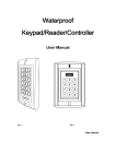
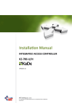
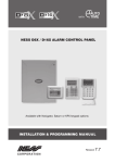
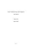
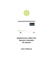
1
ress after
is any 1~4
Waterproof
ansmitted
Keypad/Reader/Controller
ternal Wiegand
erminals on the
13.56MHZ) can
external reader,
added at either
1
Supply
•
• ••
• •• •
2
3
4
5
6
7
9
8
0
#
W1-B
User manual
www.ness.com.au
“Australia’s largest
designer and
manufacturer of
high quality security
products”
Head Office:
Ness Corporation Pty Ltd
ABN 28 069 984 372
Ph +61 2 8825 9222 Fax +61 2 9674 2520
[email protected]
Sydney
Ph 02 8825 9222 Fax 02 9674 2520
[email protected]
Melbourne
Ph 03 9875 6400 Fax 03 9875 6422
[email protected]
Brisbane
Ph 07 3399 4910 Fax 07 3217 9711
[email protected]
Perth
Ph 08 9328 2511 Fax 08 9227 7073
[email protected]
Adelaide
Ph 08 8152 0000 Fax 08 8152 0100
[email protected]
N55
Installation & Programming Manual
For products:
101-095 Ness W1-B Ultraprox Reader/Controller
Copyright Notice
All rights reserved. No part of this publication may be reproduced, transmitted or stored in a retrieval system in any form or by any
means, electronic, mechanical, photocopying, recording, or otherwise, without the prior written permission of Ness.
Ness reserves the right to make changes to features and specifications at any time without prior notification in the interest of
ongoing product development and improvement.
© 2011 Ness Corporation Pty Ltd ABN 28 069 984 372
d
1. Packing list
Quantity
Name
Digital Keypad W1/W3-B
1
User Manual
1
Remark
Screw driver
1
Rubber bungs
4
6*27mm, used for fixing
Self Tapping Screws
4
3.5*27mm, used for fixing
Manager Card
2
Manager Add Card & Manager Delete Card
Please ensure that all the above contents are correct. If any are missing please notify
the supplier of the W1/W3-B.
2. Description
U
K
C
C
(W1-B&W3-B are in the same function, only different in shape . )
W1/W3-B is single door multifunction access controller or a Wiegand output keypad or
card reader. It is suitable for mounting either indoor or outdoor in harsh environments. It
is housed in a strong, sturdy and vandal proof Zinc Alloy electroplated case.
The electronics are fully potted so the W1/W3-B is waterproof and conforms to IP68.
The W1/W3-B supports up to 2500 users in either a Card, 4 digit PIN, or a Card + PIN
option. The inbuilt card reader supports EM, 125KHZ frequency card/Tag. The W1/W3B has m any extra features including block enrollment,wiegand 26 bits interface, and backlit
keypad...etc.
These features make the W1/W3-B an ideal choice for door access not only for small
shops and domestic households but also for commercial and industrial applications
such as factories, warehouses, laboratories, banks and prisons.
3. Features
Waterproof, conforms to IP68
Strong Zinc Alloy Electroplated anti-vandal case
Full programming from the keypad
2500 users, supports Card, PIN, Card + PIN
Can be used as a stand alone keypad
Programmable one relay output
Backlight keypad
Wiegand 26 input & output
Adjustable Door Output time, Alarm time, Door Open time
Block enrollment, can enroll maximum 2500 consecutive card within 3 minutes
Very low power consumption (60Ma)
Fast operating speed, <20ms with 2500 users
Easy to install and program
Built in light dependent resistor (LDR) for anti tamper
Built in buzzer
.1.
Red, Yellow and Green LEDs display the working status
12VDC Operation
Two- year warranty
4. Specifications
3
O
Operating Voltage
12VDC
Operating Humidity
5%~ 95% RH
User Capacity
2500
Environment
Conforms to IP68
12 keys, 2 x 6 digits(W1-B)
Adjustable Door Relay time 0~99 seconds
A
I
L
A
O
4. Specifications
Operating Voltage
12VDC
Operating Humidity
5%~ 95% RH
User Capacity
2500
Environment
Conforms to IP68
12 keys, 2 x 6 digits(W1-B)
Adjustable Door Relay time 0~99 seconds
12 keys, 3 x 4 digits(W3-B)
Adjustable Alarm Time 0~3 minutes
EM 125 KHZ card/Tag
Wiegand Interface
Keypad
Card Type
Card Reading Distance 3~6 cm
Active Current
80mA
Idle Current
40mA
Lock Output Load
Max 2A
Alarm Output Load
Max 20A
Operating Temperature -25
Wiegand 26 input & output
Electric Lock,Exit Button,
Wiring Connections
DOTL, External Alarm
L135 xW58 xH26 mm(W1-B)
Dimensions
60
L128 xW82 xH28 mm(W3-B)
Net Weight
550 g
Gross Weight
700 g
5. Installation
W1-B
PCB connect diagram
.2.
4
••
••
•••••
•••••
••••
••••
••••••
••
••
J1
Anti-demolition alarm
#
•••
J1
0
•••
••
••
••••
••••
••
8
••
7
9
•••••
6
••••••
2
4
•••••
1
3
5
•••
Remove the back cover from the keypad using the supplied security screwdriver
Drill 4 holes on the wall for the screws and I hole for the cable
Fix the back cover firmly on the wall with 4 flat head screws
Thread the cable through the cable hole
Attach the keypad to the back cover.
•••
It
Two- year warranty
C
6. Wiring
Colour
Function
Green
D0
Wiegand Output D0
White
D1
Wiegand Output D1
Description
Grey
Alarm -
Alarm Negative
Yellow
OPEN
Request to Exit Button
Brown
D-IN
Door Contact
Red
+12V DC
Power Input
Black
-12V DC
Power Input
Blue
NO
Relay NO
Purple
COM
Relay COM
ut
Orange
NC
Relay NC
on,
Pink
GND
W1/W3-B Negative
m
Connection Diagram
N
Alarm
•
Power +
Alarm
•••
••
••
••••••
••••
••••
•••••
•••••
••
•••
••
-
C
C
•
Pink
Power
DC
12VDC 3A
Green
White
Grey
Yellow
Exit
Button
Door
Switch
T
h
tu
r
Brown
Red
Black
R
Blue
Purple
Orange
Power +
Electric boltNC
Electric strikeNO
••••••
B)
B)
•
•
Common Power Supply
.3.
5
Lock
T
k
•••
••
••
••••••
••••
••••
•••••
•••••
••
•••
••
••
Pink
Green
• • • • • • • •• •
White
• • • • • • • •• •
Grey
Yellow
••
•
Exit
Button
Door
Switch
•
Power
•••
•••
••
•
•
••••
•••
••••
Fail-secure lock
O
•
Brown
Alarm-
Red
O
P
S
P
•
Alarm
Black
Blue
O
E
In
E
Purple
Orange
O
A
Special Power Supply
Notes:
Connect the negative pole of the lock to NC is for Fail safe lock.
Connect the negative pole of the lock to NO is for Fail-secure lock.
10
T
7. To Reset to Factory Default
To reset to factory default, power off, press * , hold it and power on, release it until
hear two beeps and the LED shines in orange, then read any two EM cards, the LED will
turn in red, means reset to factory default setting successfully. Of the two EM cards
read, the first one is Manager Add card, the second one is Manager Delete card.
Remarks: Reset to factory default, the user's information is still retained.
8. Anti Tamper Alarm
The W1/W3-B uses a LDR (light dependent resistor) as an anti tamper alarm. If the
keypad is removed from the cover then the tamper alarm will operate.
.4.
6
T
N
T
S
S
S
S
il
ll
s
d.
e
9. Sound and Light indication
Operation Status
Power on
Stand by
Press keypad
Operation successful
Operation failed
Enter into programming mode
In the programming mode
Exit from the programming mode
Open the door
Alarm
Red Light
Bright
Bright
Bright
Green Light
Bright
-
Blue Light
-
Bright
Bright
-
Bright
-
Bright
-
Buzzer
Short Ring
Short Ring
Short Ring
3 Short Ring
Short Ring
Short Ring
Short Ring
Alarm
10. W1/W3-B Detailed Programming Guide
10.1 User Settings
To enter the programming mode
To exit from the programming mode
* Master code #
888888 is the default factory master code
*
Note that to undertake the following programming the master user must be logged in
To change the master code
T
T
c
I
t
a
0 New code # New code #
The master code is any 6 digits.
Setting the working mode:
Set valid card only users
3 0 # Entry is by Card only
Set valid card and PIN users
3 1 # Entry is by Card and PIN together
Set valid card or PIN users
3 2 # Entry is by either Card or PIN (default)
T
n
N
c
f
To add and delete users in either card or PIN mode ( 3 2 # ) (Default setting)
T
T
u
.5.
7
To add a PIN users
To Delete a PIN user
To change the PIN of a PIN user
(Note:This step must be done out of
1 User ID number # PIN #
The ID number is any number between 1 ~
2500. The PIN is any four digits between 0000
~ 9999 with the exception of 1234 which is
reserved. Users can be added continuously
without exiting from programming mode as
follows:
1 User ID No 1 # PIN # UserID No 2 # PIN #
2 User ID number #
Users can be deleted continuously without
exiting programming mode
*
ID number # OldPIN # New PIN# New PIN #
programming mode)
To add a card user (Method 1)
This is a fast way to enter cards
using ID number auto generation.
1 Read Card
#
Cards can be added continuously without exiting
programming mode
To add a card user (Method 2)
This is the second way to enter
cards using User ID Allocation.
In this method a User ID is allocated
to a card. Only one user ID can be
allocated to a single card.
1 ID number # Card #
To add card user (Method 3)
Add a series cards users
Block Enrollment
5 ID number # 8 digits Card number # Card quantity #
Card quantity is between 1~2500.
The 8 digits card number is the last 8 digits on
the card.
Maximum 2500 cards can be enrolled at a stretch
within 3 minutes.
To delete card user by card
number.
Note Users can be deleted
continuously without exiting
from programming mode.
2 Read Card
To delete a card user by user ID.
This option can be used when a
user has lost their card
2 User ID
.6.
8
#
#
.
To add and delete users in card and PIN mode ( 3 1 # )
To Add a card and Pin user
(The PIN is any four digits between
0000 ~ 9999 with the exception of
1234 which is reserved.)
Add the card as for a card user
Press * to exit from the programming mode
Then allocate the card a PIN as follows:
* Read Card 1234 # PIN # PIN #
To change a PIN in card and PIN
mode (Method 1) Note that this is
done outside programming mode * Read Card Old PIN # New PIN # New PIN #
so the user can undertake this
themselves
To change a PIN in card and PIN
mode (Method 2) Note that this is
done outside programming mode * ID number# Old PIN # New PIN # New PIN #
so the user can undertake this
themselves
To delete a Card and PIN user just
delete the card
D
0 # )
The operating is the same as adding and deleting
a card user in 3 2 #
To delete All users
To delete ALL users. Note that
this is a dangerous option so use
with care
D
2 User ID #
To add a card user in card only mode ( 3
To Add and Delete a card user
10
2 0000 #
T
(
T
To add and delete card users by Manager cards
Toadd card userby ManagerAdd Card
Manager add card Read card Manager add card
Cards can be added continuously.
To delete card User by Manager
Delete Card
Manager delete card Read Card Manager delete card
Cards can bedeleted continuously.
A
T
m
N
.7.
9
#
#
d
To unlock the door
K
For a PIN user
Enter the PIN then press #
A
For a card user
Read card
T
For a card and PIN user
Read card then enter PIN #
T
10.2 Door Relay, Door Open Detection, Alarm, Facility code Settings
T
Door relay time setting
Door relay time setting
T
4 0~99 #
The door relay time is between 0~99 seconds,
the factory default setting is 5 seconds.
Door Open Detection
Door Open Too Long (DOTL) warning. When used with an optional magnetic contact
or built-in magnetic contact of the lock, if the door is opened normally, but not closed
after 1 minute, the inside buzzer will beep automatically to remind people to close
the door and continue for 1 minute before switching off automatically.
Door Forced Open warning. When used with an optional magnetic contact or built-in
magnetic contact of the lock, if the door is forced open, or if the door is opened after
20 seconds of the electro-mechanical lock not closed properly, the inside buzzer
and alarm output will both operate. The Alarm Output time is adjustable between 0-3
minutes with the default being 1 minute.
To disable door open detection.
(Factory default setting)
6 0 #
To enable door open detection
6
2
#
Alarm output time
To set the alarm output time (0~3
minutes) Factory default is 1 minute
9 0
3 #
Keypad Lockout & Alarm Output options. If there are 10 invalid cards or 10
incorrect PIN numbers in a 10 minute period either the keypad will lockout for 10
minutes or the alarm will operate for 10 minutes, depending on the option selected
below.
Normal status: No keypad lockout
or alarm
7 0 # (Factory default setting)
.8.
10
1
In
c
Keypad Lockout
7 1 #
Alarm Output
7 2 #
T
T
P
To remove the alarm
To reset the Door Forced Open warning
To reset the Door Open Too Long warning
Read valid card or Master Code #
Close the door or Read valid card or Master Code #
P
To set the facility code
To set the facility code of W1/W3B
(This operation might be required
when W1/W3-B is acting as
wiegand reader and connecting to
8 Facility code # Repeat Facility code #
Facility Code can be any number between
1~255 (Default: 0)
T
F
R
11 Interconnecting Two Devices
11.1 W1/W3-B operating as a Wiegand Output Reader
In this mode the W1/W3-B supports a Wiegand 26 bit output so the Wiegand data lines
can be connected to any controller which supports a Wiegand 26 bit input. See figure 1.
Pink
•••
Green
••
••
White
•••
Grey
••
••
••
••••••
Yellow
••••
Brown
••••
Red
•••••
•••••
Black
••
•••
Power
F
(F
d
E
Controller
Blue
••
Purple
•••
Orange
••
(With Wiegand 26 inPut)
W1/W3-B
.9.
11
1
de #
#
een
a lines
ure 1.
Transmission Format:
1: Keypad Transmission
The Reader will transmit the PIN data when it receives the last key (#) press after
PIN code.
Format: Facility Code + PIN Code
(Facility code is any digits between 0~255, factory default is 0; Pin code is any 1~4
digits between 0~9999)
Example: Facility code: 1
PIN code: 5678
Press 5678 #, then the output format will be: 00105678
2: Proximity Card Transmission
The Reader will transmit the card data when it reads the Card.
Format: Card Number (the last 8 digits of Card Number)
Remarks: No matter the card or pin is valid or invalid, the data will be transmitted
11.2 W1/W3-B operating as a Controller
In this mode the W1/W3-B supports a Wiegand 26 bit input so an external Wiegand
device with a 26 bit output can be connected to the Wiegand input terminals on the
W1/W3-B. Either an ID card reader (125KHZ) or an IC card reader (13.56MHZ) can
be connected to the W1/W3-B. Cards are required to be added at the external reader,
except where an external EM reader is used, in this case cards can be added at either
reader or controller. See figure 2.
•••
••
••
••••••
••••
••••
•••••
•••••
••
•••
••
Special Power Supply
••
•••
Pink
Wiegand reader
Green
White
Grey
••
Exit button
•••
Yellow
Brown
• •
• ••
• •
•
•
• •• •
••
•
•
Fail-Secure lock
Fail-Secure lock
••
•
Door detecting switch
•
Alarm
Red
Black
Blue
Purple
Orange
W1/W3-B
.10.
12
• ••
• •• •
W1/W3-B Quick Reference Programming Guide
To enter the programming mode
* Master code #
888888 is the default factory master code
To exit from the programming mode *
Note that to undertake the following programming the master user must be logged in
To change the master code
The master code is any 6 digits
1
To add a PIN user
To add a card user
To delete a PIN or a card user
User ID number
#
PIN
#
The ID number is any number between 1 ~ 2500.
The PIN is any four digits between 0000 ~ 9999
with the exception of 1234 which is reserved.
Users can be added continuously without exiting
programming mode
1 Read Card #
Cards can be added continuously without
exiting from programming mode
Users can be deleted continuously without
exiting from programming mode
To Unlock the door
Present the card
13