1
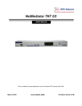
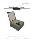
“Yo u r Part n ers i n Net w o rk Al arm Man ag emen t ”
NetGuardian Test Fixture
USER MANUAL
Visit our website at www.dpstelecom.com for the latest PDF manual and FAQs.
D-UM-TSTBX
Revision History
11/11/2013
Added NetGuardian 240T to available models and 240T info to Relay Output
10/31/2013
Removed paper manual and added Transformer to Shipping list
4/11/2013
Added additional details about correctly powering the NetGuardian and
operating the relays
10/23/2012
Added generalized support for more NetGuardian Test Boxes
10/1/12
Added Test Box 64 x 8 x 8
4/15/03
NetGuardian 32 x 8 x 8 Test Fixture User Manual (D-OC-UM034.15100)
released.
This document contains proprietary information which is protected by copyright. All rights are reserved. No part of this
document may be photocopied without prior written consent of DPS Telecom.
All software and manuals are copyrighted by DPS Telecom. Said software and manuals may not be reproduced, copied,
transmitted or used to make a derivative work, by either mechanical, electronic or any other means in whole or in part, without
prior written consent from DPS Telecom, except as required by United States copyright laws.
© 2013 DPS Telecom
Notice
The material in this manual is for information purposes and is subject to change without notice. DPS Telecom shall not be
liable for errors contained herein or consequential damages in connection with the furnishing, performance, or use of this
manual.
Contents
Visit our w ebsite at w w w .dpstelecom .com for the latest PDF m anual and FAQs
1 Introduction
................................................................................................1
2 Shipping List
................................................................................................2
3 Power and Data Connections
................................................................................................3
4 Simulating Discrete Alarms
................................................................................................5
5 Simulating Analog Alarms
................................................................................................6
6 Reading NetGuardian Relay Output
................................................................................................7
7 Technical Support
................................................................................................8
8 End User License Agreement
................................................................................................9
1
1 Introduction
Fig. 1. The NetGuardian 32 x 8 x 8 Test Fixture
The DPS Telecom NetGuardian Test Fixtures simulates all possible inputs and outputs to your NetGuardian alarm collection
remote. The Test Fixture is used to simulate alarm conditions and test NetGuardian operations.
The user interface of the Test Fixture consists of toggle switches that simulate discrete inputs, dials that simulate analog
inputs, and LEDs that light in response to control and fuse alarm outputs from the NetGuardian.
The connectors on the back panel of the Test Fixture correspond to the connectors of the NetGuardian.
This User Manual contains all the information you need to successfully connect and operate the Test Fixture. However, if you
run into a problem or require additional help, DPS Telecom's courteous Technical Support staff is ready to provide the
assistance you need. Call 1-800-622-3314 or email [email protected].
Available Test Box Models:
NetGuardian 832A G2-G5
NetGuardian 864A
NetGuardian 480
NetGuardian 420
NetGuardian 216
NetGuardian Q8
KDA Test Box
NetGuardian 240T
Note: The 32 x 8 x 8/832A Test Fixture is shown throughout the manual. The functionality for all NetGuardian Test Fixtures is
the same except for varying capacities of discrete alarms, analog alarms, and control relays. For information about alarm
display mapping/pinout information or discrete/analog capacities, see your NetGuardian's user manual.
2
2 Shipping List
While unpacking the Test Fixture, please make sure that all of the following items are included. If some parts are missing, or if
you ever need to order new parts, please refer to the part numbers in parentheses and call DPS Telecom Customer Service at
1-800-622-3314.
NetGuardian Test Fixture
(Part Number Depends on Test Fixture Purchased)
Power Supply with Connector
(D-PR-108-10A-02 for -48V or
D-PR-103-10A-01 for +24V)
Two 50-Pin M to M Ribbon Cables, 6 ft.
(D-PR-1037-10A-06)
Analog Signal Cable, 6 ft. (if applicable)
(D-PR-1035-10A-06)
Power Cable, 6ft.
(D-PR-1036-10A-06)
Power Screw Lug Barrier Plug
(1-820-00862-00)
Warranty Card
3
3 Power and Data Connections
Pow er Input
Pow er Output
Fig. 2. Power input and output
The Test Fixture has two power connections. If one is looking at the control panel of the Test Fixture, the left-hand power
connection, nearest to the Analogs 7–8 connector, is a power input providing power to the Test Fixture; the right-hand power
connection is a power output providing power to the NetGuardian unit connected to the Test Fixture. Refer to Figure 2, above.
The relays will only work if the NetGuardian unit is powered from the Power Out of the NetGuardian Test Fixture. Additionally,
both Amphenol connectors need to be connected in order for the relay LED indicators to come on.
Fig. 3. Connections between the Test Fixture and a NetGuardian. Be sure to connect both Amphenol cables before operating,
otherwise certain components may not operate correctly (such as relay LEDs).
Data connections between the Test Fixture and the NetGuardian unit to be tested are shown in Figure 3, above.
Data connections between the Test Fixture and the NetGuardian must be made before power is applied.
To connect the Test Fixture's power and data connections, follow these steps:
1. Make sure that the source power supply is off.
2. Disconnect the power input lead from the NetGuardian unit and connect it to the power input on the NetGuardian Test
Fixture.
3. Connect the NetGuardian unit to be tested to the Test Fixture's power output using the provided DC power cable. The
NetGuardian unit must be powered from the Test Fixture, or certain components (such as Relay LEDs) will not operate
properly.
4
Note: Push all power plugs firmly into their sockets. Note that the connections are keyed and the plug must be properly
aligned within the socket.
4. Using the provided analog signal cable (if your unit has analog inputs), connect the Test Fixture connector marked
"Analogs 7–8" to the NetGuardian connector marked "Analogs."
5. Using one of the provided 50-pin ribbon cables, connect the 50-pin connector above the Test Fixtures analog input dials to
the NetGuardian connector marked "Analog 1–6 Relays 1–8 Discretes 25–32."
6. Using the other 50-pin ribbon cable, connect the to 50-pin connector above the Test Fixture's toggle switches to the
NetGuardian connector marked "Discretes 1–24."
7. Move the power switch to the ON position to supply power to both the Test Fixture and the NetGuardian. The LED below
the Test Fixture's power output will light green.
Note: If the polarity of the power applied is reversed, the LED below the Test Fixture's power input will light red. This is just a
notification; the reversed polarity does not harm anything, because it is corrected inside the Test Fixture.
5
4 Simulating Discrete Alarms
Fig. 4. Alarm input switches
The toggle switches on the control panel of the Test Fixture simulate discrete alarm inputs. The number of toggle switches
will depend on the Test Fixture purchased.
The toggle switches are OFF when in the DOWN position, and ON when in the UP position.
To simulate a discrete alarm, move a toggle switch to the on position. The NetGuardian will detect the input as a discrete alarm
at the alarm point indicated by the number on the toggle switch.
6
5 Simulating Analog Alarms
Fig. 5. Analog input controls
The eight dials on the control panel of the Test Fixture simulate analog inputs.
When turned fully CLOCKWISE, the analog switch outputs 0 volts; when turned fully COUNTERCLOCKWISE, the analog
switch will output a voltage that the NetGuardian will detect as approximatley -44 volts.
To simulate an analog alarm, turn a dial counterclockwise. The analog switch will increase the voltage output in proportion to
how far the dial is turned. The NetGuardian will detect the input as an analog alarm at the alarm point indicated by the number
on the dial.
Note: The NetGuardian 480 Test Fixture does not contain analog input controls.
7
6 Reading NetGuardian Relay Output
Fig. 7. Fuse alarm and control relay indicators
The nine LEDs on the control panel of the Test Fixture indicate fuse alarm and control relay outputs from the NetGuardian.
The LED labeled "FA" indicates the fuse alarm, and will light red if the NetGuardian's fuse fails.
The LEDs labeled 1–8 indicate control relay outputs. If the NetGuardian activates a control relay, the LED with the same
number as the control relay will light green.
NetGuardian 240T & NetGuardian 480 Test Fixtures Only:
Fig. 6. Relay indicator LEDs
The relays can be simulated by browsing to the NetGuardian 240T or the NetGuardian 480's web interface and operating the
relays.
NC - Normally Closed
NO - Normally Open
When the power out from the Test Fixture is plugged into the NetGuardian and turned on, either the NC or NO relay LED
indicator will turn on (depends on if the relay is internally configured to be normally NC or NO). When the relay is operated
from the web interface, the NC LED will turn off and the NO LED will turn on, or the NO LED will turn off and the NC LED will
turn on (depending on how the relay is internally configured).
8
7 Technical Support
DPS Telecom products are backed by our courteous, friendly Technical Support representatives, who will give you the best in
fast and accurate customer service. To help us help you better, please take the following steps before calling Technical
Support:
1. Check the DPS Telecom website.
You will find answers to many common questions on the DPS Telecom website, at http://www.dpstelecom.com/support/.
Look here first for a fast solution to your problem.
2. Prepare relevant information.
Having important information about your DPS Telecom product in hand when you call will greatly reduce the time it takes to
answer your questions. If you do not have all of the information when you call, our Technical Support representatives can
assist you in gathering it. Please write the information down for easy access. Please have ready your User Manual and
hardware serial number.
3. Have access to troubled equipment.
Please be at or near your equipment when you call DPS Telecom Technical Support. This will help us solve your problem
more efficiently.
4. Call during Customer Support hours.
Customer support hours are Monday through Friday, from 7 A.M. to 6 P.M., Pacific time. During these hours Technical
Support representatives are on duty in our fully equipped simulation lab.
Emergency Assistance: Emergency assistance is available 24 hours a day, 7 days a week. For emergency
assistance after hours, allow the phone to ring until it is answered with a paging message. You will be asked to
enter your phone number. An on-call technical will return your call as soon as possible.
9
8 End User License Agreement
All Software and firmware used in, for, or in connection with the Product, parts, subsystems, or derivatives thereof,
in whatever form, including, without limitation, source code, object code and microcode, including any computer
programs and any documentation relating to or describing such Software is furnished to the End User only under a
non-exclusive perpetual license solely for End User's use with the Product.
The Software may not be copied or modified, in whole or in part, for any purpose whatsoever. The Software may not
be reverse engineered, compiled, or disassembled. No title to or ownership of the Software or any of its parts is
transferred to the End User. Title to all patents, copyrights, trade secrets, and any other applicable rights shall
remain with the DPS Telecom.
DPS Telecom's warranty and limitation on its liability for the Software is as described in the warranty information
provided to End User in the Product Manual.
End User shall indemnify DPS Telecom and hold it harmless for and against any and all claims, damages, losses,
costs, expenses, obligations, liabilities, fees and costs and all amounts paid in settlement of any claim, action or
suit which may be asserted against DPS Telecom which arise out of or are related to the non-fulfillment of any
covenant or obligation of End User in connection with this Agreement.
This Agreement shall be construed and enforced in accordance with the laws of the State of California, without
regard to choice of law principles and excluding the provisions of the UN Convention on Contracts for the
International Sale of Goods. Any dispute arising out of the Agreement shall be commenced and maintained only in
Fresno County, California. In the event suit is brought or an attorney is retained by any party to this Agreement to
seek interpretation or construction of any term or provision of this Agreement, to enforce the terms of this
Agreement, to collect any money due, or to obtain any money damages or equitable relief for breach, the prevailing
party shall be entitled to recover, in addition to any other available remedy, reimbursement for reasonable attorneys'
fees, court costs, costs of investigation, and other related expenses.
10
11
Warranty
DPS Telecom warrants, to the original purchaser only, that its products a) substantially conform to DPS' published
specifications and b) are substantially free from defects in material and workmanship. This warranty expires two years from the
date of product delivery with respect to hardware and ninety days from the date of product delivery with respect to software.
If the purchaser discovers within these periods a failure of the product to substantially conform to the specifications or that
the product is not substantially free from defects in material and workmanship, the purchaser must promply notify DPS. Within
reasonable time after notification, DPS will endeavor to correct any substantial non-conformance with the specifications or
substantial defects in material and workmanship, with new or used replacement parts. All warranty service will be performed at
the company's office in Fresno, California, at no charge to the purchaser, other than the cost of shipping to and from DPS,
which shall be the responsiblity of the purchaser. If DPS is unable to repair the product to conform to the warranty, DPS will
provide at its option one of the following: a replacement product or a refund of the purchase price for the non-conforming
product. These remedies are the purchaser's only remedies for breach of warranty. Prior to initial use the purchaser shall have
determined the suitability of the product for its intended use. DPS does not warrant a) any product, components or parts not
manufactured by DPS, b) defects caused by the purchaser's failure to provide a suitable installation environment for the
product, c) damage caused by use of the product for purposes other than those for which it was designed, d) damage caused
by disasters such as fire, flood, wind or lightning unless and to the extent that the product specification provides for
resistance to a defined disaster, e) damage caused by unauthorized attachments or modifications, f) damage during shipment
from the purchaser to DPS, or g) any abuse or misuse by the purchaser.
THE FOREGOING WARRANTIES ARE IN LIEU OF ALL OTHER WARRANTIES, EXPRESS OR IMPLIED, INCLUDING BUT
NOT LIMITED TO THE IMPLIED WARRANTIES OF MERCHANTABILITY AND FITNESS FOR A PARTICULAR
PURPOSE.
In no event will DPS be liable for any special, incidental, or consequential damages based on breach of warranty, breach of
contract, negligence, strict tort, or any other legal theory. Damages that DPS will not be responsible for include but are not
limited to, loss of profits; loss of savings or revenue; loss of use of the product or any associated equipment; cost of capital;
cost of any substitute equipment, facilities or services; downtime; claims of third parties including customers; and injury to
property.
The purchaser shall fill out the requested information on the Product Warranty Card and mail the card to DPS. This card
provides information that helps DPS make product improvements and develop new products.
For an additional fee DPS may, at its option, make available by written agreement only an extended warranty providing an
additional period of time for the applicability of the standard warranty.
Technical Support
If a purchaser believes that a product is not operating in substantial conformance with DPS' published specifications or there
appear to be defects in material and workmanship, the purchaser should contact our technical support representatives. If the
problem cannot be corrected over the telephone and the product and problem are covered by the warranty, the technical
support representative will authorize the return of the product for service and provide shipping information. If the product is
out of warranty, repair charges will be quoted. All non-warranty repairs receive a 90-day warranty.
“Dependable, Powerful Solutions
that allow users to monitor larger,
more complicated networks with a
smaller, less trained staff”
“Yo u r Part n ers i n Net w o rk Al arm Man ag emen t ”
www.dpstelecom.com
4955 E. Yale • Fresno, CA 93727
(559) 454-1600 • (800) 622-3314 • (559) 454-1688 fax