1
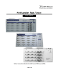
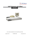
Building Access System G2, G3, & G4
For the NetGuardian 832A G2/G4/G5 and 216F
USER MANUAL
Visit our website at www.dpstelecom.com for the latest PDF manual and FAQs.
March 4, 2014
D-UM-ECUG4
ECU Firmware Version 1.0A
Revision History
March 4, 2014
Added support for 35-bit cards
November 11, 2013
Fixed jumper number for disabling the internal speaker
May 30, 2013
Added support for ProxPro keypad/proxy reader
October 19, 2012
Added ECU G4 support
October 31, 2011
Added Emergency Unlock mode and Double Swipe mode information
December 6, 2010
Corrected information on "Additional Switch Settings"
June 24, 2010
Added info on Magnetic Door Mode.
February 16, 2010
Additions made to user manual for ECU G3 with dual proxy option.
June 3, 2009
Revisions for NetGuardian 216F
March 28. 2008
Derived from ECU G1 manual. This manual applies to the ECU G2 and
not the G1.
April 16, 2008
Initial release.
This document contains proprietary information which is protected by copyright. All rights are reserved. No part of this
document may be photocopied without prior written consent of DPS Telecom.
All software and manuals are copyrighted by DPS Telecom. Said software and manuals may not be reproduced, copied,
transmitted or used to make a derivative work, by either mechanical, electronic or any other means in whole or in part, without
prior written consent from DPS Telecom, except as required by United States copyright laws.
© 2014 DPS Telecom
Notice
The material in this manual is for information purposes and is subject to change without notice. DPS Telecom shall not be
liable for errors contained herein or consequential damages in connection with the furnishing, performance, or use of this
manual.
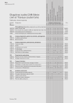
Contents
Visit our w ebsite at w w w .dpstelecom .com for the latest PDF m anual and FAQs
1 Introduction
1.1 ECU G2 vs. ECU G3 vs. ECU G4
1.2 Shipping List
2 Specifications
3 Hardware Installation
3.1 Site Preparation
3.2 Installation Overview
3.3 Mounting Instructions
3.3.1 Entry Control Unit
3.3.2 ECU with conduit
3.3.3 Keypad
3.3.4 Card Reader
3.4 Opening the Case
3.5 Power Connection
3.5.1 Entry Control Unit
3.5.2 Door Strike
3.5.3 ECU Relay Fuse
3.6 Communication Lines
3.6.1 NetGuardian 832A G4/G5
3.6.2 NetGuardian 832A G2
3.6.3 NetGuardian 216F
3.6.4 Entry Control Unit G2, G3, and G4
3.6.5 Daisy Chain Options
3.6.6 Keypad
3.6.7 Proxy Reader
3.6.8 HID ProxPro Keypad/Proxy Reader
4 Unit Configuration
4.1 Addressing the Entry Control Unit
4.1.1 Additional Switch Settings
5 Operation
5.1 Entry Control Unit Operation
5.1.1 LED Verification and Local Testing
5.1.2 Speaker Operation
5.1.2.1 ECU Internal Speaker
5.1.2.2 ECU External Speaker (G3 Only)
5.1.3 Connecting via the DB9 Craft Port (G3 Only)
5.1.4 Connecting via the USB Craft Port (ECU G4)
5.1.5 Firmware Upgrade (G3 Only)
5.1.6 Firmware Upgrade (G4 Only)
5.2 Keypad LED Operation
5.2.1 Basic Operation
6 Display Mapping Appendix A
7 Determining Proximity Card Number
8 End User License Agreement
1
3
5
9
10
10
10
11
11
11
12
12
13
14
14
16
18
19
19
20
21
22
24
25
26
27
29
29
31
33
33
35
35
36
37
38
40
46
47
47
48
49
50
54
1
1 Introduction
The Building Access System (BAS) is a comprehensive building entry management system that provides
centralized door access control. With the system in place, managers can maintain a database of all personnel
access as well as the time of day and location that access was granted. The four part system consists of T/
MonXM, the NetGuardian 832A, the Entry Control Unit (ECU), and optional keypad or proximity card reader.
•
•
•
•
•
•
•
•
Centralized entry management and control.
Controls and regulates up to 16 door entry points.
Users can be granted access by day of the week, time of day, and location.
Supports small to medium sized sites.
Each site functions independent of the master.
ECU G2 supports both keypad and proxy card entry methods.
ECU G3 supports a dual proxy reader build option.
ECU G4 supports a dual proxy reader and dual keypad build option.
T/MonXM software
The BAS system functions as a software module in T/MonXM software. It is a profile based access system that
assigns each user with a unique user profile that contains information on which doors are allowed to be accessed,
the days of the week access is allowed, a start and stop time, and a beginning and ending date (primarily for
contractors, new employees, or short term employees). The user profile field includes the user’s name, title,
numeric user ID (7 digit minimum - 14 digit maximum), and a 30 character miscellaneous description.
NetGuardian 832A G2/G4/G5 and NetGuardian 216F
The NetGuardian maintains a list of personnel who are authorized to access the facility. It records all valid entries,
attempts, and the time of each action. It can also receive a control from T/MonXM to remotely open a door. However,
should the NetGuardian lose connection with the T/MonXM, the unit is still able to make local entry decisions. Front
panel LEDs indicate communication activity between the NetGuardian and the ECU. The unit supports up to 1,300
user profiles for distribution between door entry points.
Entry Control Unit (ECU G2, G3, and G4)
The Entry Control Unit reduces and distributes the control and interface logic of the NetGuardian. Any access code
that is entered on the keypad or card reader is accepted by the ECU and passed on to the NetGuardian for
validation. If the access code is valid, the ECU accepts a command from the NetGuardian to energize the local relay
to open the door. In the event of communication failure with the NetGuardian, the ECU will verify entered access
codes against a backup access profile previously configured in and downloaded from the NetGuardian. The ECU is
powered by -48VDC and is wall mountable on the interior of the building. The unit has front panel LEDs indicating
fuse alarm, door status, entry status, shelf status, craft port activity and NetGuardian communication.
Keypad (Accessory Sold Separately)
The weather-shielded keypad is mounted on the exterior of the building and is designed to withstand a wide
temperature range. To prevent unauthorized access, there is no amount of tampering that can be done to the
keypad to cause the door to open.
Proxy Reader (Accessory Sold Separately)
The weather-proofed proximity reader is mounted on the exterior of the building and is designed to withstand a wide
temperature range. As with the keypad, there is no amount of tampering that can be done to the proxy reader to
cause the door to open. The ECU supports +12V, 26-bit, 35-bit or 37-bit Wiegand card readers.
2
Note: With optional Dual-RS485 ports, one NetGuardian can handle up to 16 entry points. (8 entry points on each
port)
3
1.1 ECU G2 vs. ECU G3 vs. ECU G4
Depending on your desired configuration, you'll order with the ECU as part of your Building Access System. If you
plan on using both the Proxy Reader AND Keypad, you'll use the ECU G2, which supports both. The ECU G3
supports a dual Proxy Readers, for using one Proxy inside and outside of a building. The ECU G4 supports dual
Proxy Readers or Keypads both inside and outside of a building.
ECU G2 - Supports Proxy Reader and Keypad (1 each)
ECU G3 - Supports Dual Proxy Readers (1 inside, 1 outside)
ECU G4 - Supports Dual Proxy Readers, Dual Keypads, or Combination (2 inside, 2 outside)
New on the ECU G3 & G4 - See Section 4.1.1, "Additional Switch Settings", for details on configuring
dip switches for these modes.
"Dual Keypad Mode" - In this mode on the ECU G4, you can mount one Proxy Card Reader and One Keypad both
inside your building and outside. This is used for additional versatility for clocking employees in and out for the day.
"Dual Proxy Mode" - Used in this mode, you will mount one Proxy Card Reader inside your building and one
outside. This is used for clocking employees in and out for the day.
"Magnetic Door Mode" - This mode may be used with doors equipped with magnetic door locks. In this mode, the
door will remain magnetically locked until unlocked via proxy card scan, Request-to-Exit button, or motion sensor.
4
NOTE: Door violations occur when the door is opened without being unlocked. Pushing a Request-to-Exit button or
triggering the motion sensor after the intrusion will not cancel the violation.
"Lock When Closed Mode" - This mode causes the door to lock a few seconds after it has been detected closed,
and can be usefully combined with "Magnetic Door Mode" to ensure building security before and after the door has
been unlocked. In this mode, if the door does not open after it has been unlocked, It will lock again after 2-3
seconds.
"Emergency Mode" - This mode causes all doors to unlock in the event that a user-defined gas and fire alarm
occur. This mode defaults Off but can be activated through the NetGuardian G5 Web browser interface. Both alarms
have to be active in order for NetGuardian to issue the unlock command, and the gas alarm must clear before the
doors can be re-locked when in this mode.
NOTE: "Emergency Mode" only available in NetGuardian G5 v5p3K.
"Double Swipe Mode" - Allows users to locally enable propped door mode by swiping their access card a second
time during the door unlock period. For activation information see Section 4.1.1 "Additional Switch Settings."
NOTE: "Double Swipe Mode" only available in ECU G3 V3.0D (and above) or ECU G4.
5
1.2 Shipping List
While unpacking the ECU, please make sure that all of the following items are included. If some parts are missing,
or if you ever need to order new parts, please refer to he part numbers listed and call DPS Telecom at (800) 6223314.
ECU Box
Entry Control Unit
(D-PK-ECUG2 or D-PK-ECUG3 or D-PK-ECUG4)
Building Access user manual
(D-UM-ECUG4)
Four wall mount bracket screws
(2-000-60250-01)
Four wall mount bracket screws
(2-000-80750-03)
Wall Mount Brackets
(D-CS-532-10A-05)
One 4-pin comm line screw-lug
(2-820-00814-02)
Two 3/4 amp fuses
(2-741-00750-00)
One 2-pin fuse relay screw lug
(2-820-00812-02)
6
ECU G4
6 ft. USB Craft Port Cable
D-PR-046-10A-06
Building Access Resource Disk
Locking 2-pin power screw-lug jack
(2-820-35102-00)
ECU G3
One 2-pin power screw-lug jack
(2-820-00862-02)
7
Keypad Box (Sold Separately)
One 14 foot cable.
(D-PK-KEYPD-12001.0001)
One environmentally sealed Keypad.
(D-PK-KEYPD-12001.0001)
Keypad mounting template
(D-OC-ECUMOUNTING)
Four mounting screws
(1-000-80750-50)
8
Proximity Reader Box (Sold Separately) (D-PK-PROXI-12001)
One HID ThinLine Proximity Card Reader
w/12" RJ-45 Cable
(D-PR-530-10A-00)
One Unshielded RJ45 to RJ45 CAT 5 Coupler
(D-PR-534-10A-01)
Two HID Mounting Screws
One demo card from HID
(D-PR-534-10A-00)
One HID Mounting Instructions
9
2 Specifications
Specification
ECU G4
ECU G2 and G3
Keypad (Sm)
Keypad (Lg)
Proxy Reader
Dimensions
9"W x 7.62"H x
1.72"D
8.56” x 7.5” x 1.72”
3”x 5” x 2 ½ “
4 ½” x 5” x 2 ½”
4.7" x 3" x 0.68"
Mounting
wall mount
wall mount
wall mount
wall mount
wall mount
Weight
1.79lb*
3lb (1.36kg)**
0.5lb (0.225kg)
1lb (0.45kg)
1lb (0.45kg)
Power Input
-48 VDC
-48 VDC
N/A
N/A
5-16 VDC
Current Draw
80 mA
35 mA
N/A
N/A
30 mA
RJ45
RJ45
RJ45
Interfaces
1 four-pin screw lug 1 four-pin screw lug
jack
jack
Protocols
N/A
N/A
N/A
N/A
Wiegand
(26/35/37 bit)
Temp. Range
0° to 60°C
(32° to 140°F)
0° to 60°C
(32° to 140°F)
-40° to +80°C
(-40° to +176°F)
-40° to +80°C
(-40° to +176°F)
-30° to 65°C
(-22° to +150°F)
Humidity
Range
0% to 95%
non-condensing
0% to 95%
non-condensing
environmentally
sealed
environmentally
sealed
0%-95%
non-condensing
Fuse
GMT ¾ amp
GMT ¾ amp
N/A
N/A
N/A
Audible
Speaker
Speaker
N/A
N/A
Speaker
Visual
LEDs
LEDs
LEDs
LEDs
LED
MTBF
60 years
60 years
-
-
-
Windows
Compatibility
XP, Vista, 7 32/64
bit
XP, Vista, 7 32/64
bit
-
-
-
Note: Proxy reader specifications are based on the ThinLine II card reader from the HID Corporation.
12VDC power is supplied to the reader by the ECU.
*Unit weight (not including hardware kit)
**Unit weight (including hardware kit)
10
3 Hardware Installation
3.1 Site Preparation
Tools needed:
Phillips screwdriver
Wire strippers/cutter
Small standard No.2
screwdriver (1/16" for screw-lug
connectors)
Materials needed:
• 1/2” conduit
Precautions
• Pull GMT fuse before connecting ECU power feed.
• Always observe electrostatic discharge (ESD) precautions.
3.2 Installation Overview
1. Mount the ECU and the Keypad and/or Proxy Reader.
2. Connect power to the ECU.
3. Connect communication lines between the NetGuardian, ECU, and Keypad and/or Proxy Reader
4. Set the ECU address(es).
5. Provision the NetGuardian and the T/MonXM with the appropriate information. (See the BAS software module
in the T/MonXM user manual)
11
3.3 Mounting Instructions
3.3.1 Entry Control Unit
The Entry Control Unit can be wall mounted by using the provided rack ears. These will need to be screwed onto
both sides of the unit.
Fig. 3.1
3.3.2 ECU with conduit
The 3/4” circular openings support standard 1/2” conduit fittings (not included).
Secure power and communication wires by installing 1/2” inch conduit in any
of the 3/4” circular openings on the ECU.
To attach the conduit, remove the 3/4” pre-cut metal circles from the case and insert the 1/2” conduit or the nylon
plug.
Fig. 3.2
12
3.3.3 Keypad
1. Mount the keypad bracket on the desired surface using the four screw holes by using the mounting bracket
2. Before securing the keypad onto the bracket, weave the RJ45 cable through the securing barriers and out the
circular bracket opening.
3. Secure the keypad onto the bracket by inserting the four side panel screws into the unit.
Fig. 3.3
3.3.4 Card Reader
1. Add RJ cable lead to the reader according to ECU pinout. Make sure cable length is adequate to reach the ECU
or use an RJ coupler w/CAT5 extension cable. Maximum length is 300 feet.
RJ45 Pin #
HID Wire Color
Function
1
Red
+12 VDC Power
2
N/C
Do Not Connect
3
White
Data1
4
Green
Data0
5
N/C
Do Not Connect
6
N/C
Do Not Connect
7
N/C
Do Not Connect
8
Black
Ground
RJ-45 pinout information
2. Mount the reader on the desired surface according to mounting instructions provided by card reader manufacturer.
13
3.4 Opening the Case
The entire ECU cover does not need to be taken off to access the internal screw-lugs, dip switches, fuse or RJ45
connectors for the keypad and proxy reader. The front panel is broken up into two parts. The upper half can be
unscrewed and hinged from the unit to access most of the ECU internal controls.
Fig. 3.4
To open the upper half of the ECU case, follow these steps:
1. Locate the screws on both sides of the unit.
2. Remove each screw on the upper part of the unit only. Do not remove the screws that are holding the bottom
portion of the front panel.
3. When both screws have been removed from the upper half of the front panel, gently swing it open to access the
inside of the ECU.
14
3.5 Power Connection
3.5.1 Entry Control Unit
The Grounding Lug on the side of the unit provides a permanent connection to earth ground when
connected. The Grounding Lug must be used in order to comply with CE standards.
Fig. 3.5
Before you connect a power supply to the ECU, test the voltage of your power supply:
Connect the black common lead of a voltmeter to the ground terminal of the battery, and connect the red lead of
the voltmeter to the battery's –48 VDC terminal. The voltmeter should read between –43 and – 53 VDC. If the
reading is outside this range, test the power supply.
To connect the ECU to a power supply, follow these steps:
1. Always use safe power practices when making power connections. Be sure to remove fuses from the fuse
distribution panel, as well as the ECU, before making your power connections.
2. Use the grounding lug to connect the unit to earth ground. The grounding lug is next to the symbol
. Insert
the eyelet of the earth ground cable between the two bolts on the grounding lug (Ground cable not included).
3. Insert a battery ground into the power connector plug's right terminal and tighten the screw; then insert a battery
line to the plug's left terminal and tighten its screw.
4. Insert a fuse into the fuse distribution panel and measure voltage. The voltmeter should read between –40 and –
70VDC.
15
5. The power plug can be inserted into the power connector only one way to ensure the correct polarity. Note that
the negative voltage terminal is on the left and the GND terminal is on the right.
6. Insert fuse into the Power fuse slot. The power LED should be lit green. If the LED is red, the power connection is
reversed. To confirm that power is correctly connected, the front panel LEDs will flash RED and GREEN,
indicating that the firmware is booting up.
Note: Observe polarity when connecting battery leads. If using the -48VDC red/black cables supplied with the unit,
connect black to GND and red to -BATT. Standard gauge is 20AWG, but may vary between 18-24AWG.
Fig. 3.6
FA Relay on the bottom of the unit contains the contact closures for the fuse relay. This will close when the 3/4
amp gmt fuse has blown and will normally be open. Use the included 2-pin screw lug. This looks the same as the 4pin comm line screw lug used for connecting the ECU to a NetGuardian RS485 port or when connecting several
ECU's together with a daisy chain configuration except this connector only has 2 pins.
16
3.5.2 Door Strike
When a valid password is entered on the keypad, the NetGuardian will send a command to the ECU to operate the
relay to energize the door strike.
Follow the directions below to connect the door strike and door sensor to the ECU.
1) Use the screw-lug connectors. If using a 24VDC door strike, connect the door strike power wires to SPB (+) and
SNeg (-)/GND. If using a 12VDC door strike, connect the power wires to SPA(+) and SNeg(-)/GND.
2) Connect the door sensor to RTN (return) and ALM1 (opto isolated alarm for the door sensor).
Fig. 3.7
Note: The ECU G4 does not support the external speaker option.
17
Output Connections
Screw-Lugs
Description
SPB+
Positive switched power source (24VDC). Can be used for door strike.
SNeg/GND
Negative switched power source. Can be used for door strike. This is used by either SPB+ or
SPA+.
SPA+
Positive switched power source (12VDC). Can be used for door strike.
UPB+
Positive un-switched power source. (24VDC)
UNeg/GND
Negative un-switched power source. This has 2 connections and both are the same. For use
with UPA+ or UPB+.
Can be used to power the motion sensor or other external accessory.
UPA+
Positive un-switched power source (12VDC). Can be used to power the motion sensor or other
external accessory.
RNO
Relay normally open.
RCO
Relay common.
RNC
Relay normally closed
Input Connections
Screw-Lugs
Description
ALM1
Isolated alarm for door sensor.
RTN
Door sensor return.
ALM2
Request to exit button or motion sensor
RTN
Button or motion sensor return.
ALM3
Reserved for future use.
RTN
Reserved for future use.
Tbl. 2.2.5.2b - ECU screw -lug jack descriptions
18
3.5.3 ECU Relay Fuse
If the unit fails to power the door strike, motion sensor, or proxy reader, then make sure the fuse inside the unit has
not blown.
Replace with a 1amp fuse (Part number 2-740-01000-00) if necessary.
Fig. 3.8
19
3.6 Communication Lines
3.6.1 NetGuardian 832A G4/G5
The NetGuardian’s RS485 ports can support up to 8 ECU’s each. If connecting more than one ECU, use a daisychain configuration as needed (See section 2.2.6.4 for daisychain options).
Note: If using a daisy-chain configuration, there is a maximum connection length of 1,500 feet b etween the NetGuardian
and the last ECU.
Fig. 3.9
Pin
Signal
1
TX+
2
NC
3
RX+
4
GND
5
GND
6
RX-
7
NC
8
TX-
Fig. 3.10 - NetGuardian RS485 RJ45 pinout inform ation
20
3.6.2 NetGuardian 832A G2
The NetGuardian’s RS485 ports can support up to 8 ECU’s each. If connecting more than one ECU, use a daisychain configuration as needed (See section 2.2.6.4 for daisychain options). Use cable number D-PR-652-10A-00.
Note: If using a daisy-chain configuration, there is a maximum connection length of 1,500 feet b etween the NetGuardian
and the last ECU.
Fig. 3.11
Pin
Signal
NG Pin #
Wire Color
1
TX+
1 (TX+)
Wht/Blu
2
NC
4 (RX+)
Wht/Org
3
NC
6 (TX-)
Blu/Wht
4
RX+
9 (RX-)
Org/Wht
5
NC
6
TX-
7
NC
8
NC
9
RX-
Fig. 3.12 - NetGuardian RS485 pinout inform ation
21
3.6.3 NetGuardian 216F
The NetGuardian’s RS485 ports can support up to 8 ECU’s each. If connecting more than one ECU, use a daisychain configuration as needed (See section 2.2.6.4 for daisychain options).
Fig. 3.13 - NetGuardian 216F's Back Panel w ith RS485 Port
Pin
Signal
1
TX+
2
NC
3
RX+
4
GND
5
GND
6
RX-
7
NC
8
TX-
Fig. 3.14 - NetGuardian RS485 RJ45 pinout inform ation
22
3.6.4 Entry Control Unit G2, G3, and G4
The ECU distributes the control and interface logic of the NetGuardian BAC.
To connect the ECU to the NetGuardian BAC, follow the directions below:
1. Connect the ECU to one of the 4-wire RS485 ports located on the back panel of the NetGuardian. You may use
cable number D-PR-652-10A-00 if connecting ECU to a NetGuardian 832A G2.
2. Connect communication wires from the NetGuardian host to the ‘Primary' 4-position barrier plug.
3. If daisy chaining, connect the communication wires of the second ECU you are using into the screw lug jacks of
the first ECU.
Fig. 3.15 - Connect the NetGuardian to the ECU using cable num ber D-PR-652-10A-00
NG G2
Pin #
To ECU
NG G4/G5
Pin #
To ECU
1 TX+
RX+
1 TX+
RX+
4 RX+
TX+
3 RX+
TX+
6 TX-
RX-
8 TX-
RX-
9 RX-
TX-
6 RX-
TX-
NetGuardian to ECU Interface Cable Pinout Inform ation
(D-PR-652-10A-00)
23
Fig. 3.16 - Diagram dem onstrating w hich RJ45 port corresponds to w hich keypad/proxy reader
24
3.6.5 Daisy Chain Options
Up to eight ECUs can be connected to one RS485 port on the NetGuardian
(there is a maximum distance of 1,500 feet between the NetGuardian and the last ECU in the daisy chain).
To connect the ECUs in a daisy chain configuration, connect communication lines between the ECUs
in a parallel fashion (i.e. TX+ to TX+, TX- to TX-, RX+ to RX+, and RX- to RX-).
Fig. 3.17 - ECU Daisy Chain Configuration
25
3.6.6 Keypad
For the keypad option, you'll use the ECU G2 (DPS part number D-PK-ECUG2) or ECU G4 (DPS part number DPK-ECUG4). The keypad interfaces with the ECU via an RJ45 cable (attached to the keypad). The ECU has five
circular openings (two on top, two on the side and one on bottom) where the RJ45 cable can be inserted. The RJ45
jack is located on the inside of the ECU casing. Insert the RJ45 cable through one of the openings and connect it to
the RJ45 jack labeled "Keypad".
Note: The ECU G4 also supports dual keypads - for b oth the inside and the outside of a b uilding.
Note: There is a maximum distance of 14 feet b etween the keypad and the ECU.
Fig. 3.18 - Connect the RJ45 cable from the keypad to the ECU
26
3.6.7 Proxy Reader
The proxy reader interfaces with the ECU via an RJ45 cable (attached to the proxy reader). The ECU has five circular
openings (two on top, two on the side and one on bottom) where the RJ45 cable can be inserted. The RJ45 jack is
located on the inside of the ECU casing. Insert the RJ45 cable through one of the openings and connect it to the
RJ45 jack labeled "Proxy".
Dual Proxy Mode
To use 2 proxy readers for entry and exit logging, use the ECU G3 (DPS part number D-PK-ECUG3) or ECU G4
(DPS part number D-PK-ECUG4), which supports this mode. Inside the ECU G3 or G4 case, you will notice the
jacks are clearly labeled Proxy Outside and Proxy Inside. You also have the option to purchase the ECU G3 or G4
as a package with dual proxy readers: DPS part number D-PK-BAPKG-12001.00001.
Note: There is a recommended maximum distance of 300 feet b etween the proxy reader and the ECU.
Fig. 3.19 - Connect the RJ45 cable from the reader to the ECU
RJ45 Pin #
HID Wire Color
Function
1
Red
+12 VDC Power
2
N/C
Do Not Connect
3
White
Data1
4
Green
Data0
5
N/C
Do Not Connect
6
N/C
Do Not Connect
7
N/C
Do Not Connect
8
Black
Ground
RJ45 pinout information (Proxy reader)
RJ45 Connector
27
3.6.8 HID ProxPro Keypad/Proxy Reader
The proxy reader/keypad interfaces with the ECU via an RJ45 cable. The ECU has five circular openings (two on top,
two on the side and one on bottom) where the RJ45 cable can be inserted. The RJ45 jack is located on the inside of
the ECU casing. Insert the RJ45 cable through one of the openings and connect it to the RJ45 jack labeled "Proxy
A" or "Proxy B".
First, remove the front plate of the ProxPro unit.
After the front plate has been removed, 4 holes
containing screws will be revealed. Remove all 4
screws.
From the inside of the unit, locate the screw
connectors. This is where you'll attach the wires to the
RJ45 connector.
Match the corresponding wire to the screw connector.
See pinout table below for additional information.
28
Match the corresponding wire to the appropriate pin on Put the two pieces back together. First, on the inside
the RJ45 connector. See pinout table below for
cover, locate the 10-pin male connector. This
additional information.
connector will need to correspond to the 10-pin female
connector on the board on the base unit (image
below).
RJ45 Connector
RJ45 Connector Pinout
ProxPro Connector Pinout
RJ45 Pin #
Function
Connector*
Function
1
DC+ (Red)
1
DC+ (RED)
2
No Connect
2
Ground (BLACK)
3
Data 1
3
Data 1/Clock (WHITE)
4
Data 0
4
Data 0/Data (GREEN)
5
No Connect
5
No Connect
6
No Connect
6
No Connect
7
No Connect
7
No Connect
8
Ground
8
No Connect
*Starts from DC+ (RED) and goes down vertically
29
4 Unit Configuration
4.1 Addressing the Entry Control Unit
Each ECU must be given a unique address. There are two eight-position switches located on the ECU circuit board
that allows you to set various configurations. One is labeled CONFIG1 and is used for setting a unique address for
each unit. However, only the first 4 switches on CONFIG1 are used for addressing the units (See figure the
following table for additional address switch positions). See section the Additional Switch Settings section for more
switch settings.
Fig. 4.1
30
ECU Address
DIP 1
DIP 2
DIP 3
DIP 4
1
OFF
OFF
OFF
OFF
2
ON
OFF
OFF
OFF
3
OFF
ON
OFF
OFF
4
ON
ON
OFF
OFF
5
OFF
OFF
ON
OFF
6
ON
OFF
ON
OFF
7
OFF
ON
ON
OFF
8
ON
ON
ON
OFF
9
OFF
OFF
OFF
ON
10
ON
OFF
OFF
ON
11
OFF
ON
OFF
ON
12
ON
ON
OFF
ON
13
OFF
OFF
ON
ON
14
ON
OFF
ON
ON
15
OFF
ON
ON
ON
ON
ON
ON
ON
16
Addressing sw itch positions
*DIP switches for addressing is on CONFIG1.
31
4.1.1 Additional Switch Settings
Fig. 4.2
Config 1 DIP Settings
DIP
Description
Switch
1-4
Used for ECU Addressing.
5
Craft port debug.
"On" enables debug on the craft port at 115200 baud.
(Default) "Off" disables debug on the craft port.
6
Relay settings. Controls relay 1 and relay 2. Used to control the door strike.
"On" sets relays to Normally Closed. The relay will idle in an energized state. When a valid code is
entered, the relay will de-energize - releasing the door strike.
(Default) "Off" sets relays to Normally Open. In this configuration, when a valid code is entered the relay
energizes and activates the door strike.
7
Baud rate settings for communication with the NetGuardian. "On" sets primary baud rate to 9600.
(Default) "Off" sets primary baud rate to 19200.
8
ECU ALM points settings. "On" reverses ECU ALM points 1-3. (Default) "Off" sets ECU ALM points 13 to Normal.
Note: A system reboot is required after every new DIP switch configuration.
32
Config 2 DIP Settings
DIP
Switch
Description
1
ONLY USED FOR THE ECU G3 OR G4. "On" puts the ECU G3 in dual proxy mode. If using this
mode, the NetGuardian must have Direction enabled. See the NetGuardian G5 user manual for details.
2
ONLY USED FOR THE ECU G3 OR G4. "Off" puts the ECU G3 in Door Strike Mode (default), while
flipping the switch "On" puts the unit in Magnetic Door Mode. See Section 1.1 "ECU G2 vs. ECU G3"
for details.
3
ONLY USED FOR THE ECU G3 OR G4. "On" puts the ECU G3 in Lock When Closed Mode, which
locks the door a short time after it's shut. This mode can be combined with Magnetic Door Mode.
See section 1.1 "ECU G2 vs. ECU G3" for details. The switch is "Off" by default.
4
ONLY USED FOR THE ECU G3 OR G4. "On" puts ECU G3 in Double Swipe Mode. This mode
allows you to locally start propped door mode by scanning a currently active access card once to
unlock the door, then a second time while the door is unlocked. See the NetGuardian Web Browser
User Manual for details on setting the propped door timeout. The switch is "Off" by default.
5-7
8
Reserved for future use.
Legacy mode / G2 mode. DPS recommends this setting to be off. "On" sets the unit to run in G2 mode.
(This is not compatible with all versions of NetGuardian and T/Mon.) (Default) "Off" sets the unit to run
in legacy mode (G1). Note: This mode is not supported on the ECU G4.
Note: For deployment of 5 ECUs or more, DPS recommends 19200 baud polling by setting CONFIG1 switch 7 to
"Off".
Note: A system reboot is required after every new DIP switch configuration.
33
5 Operation
5.1 Entry Control Unit Operation
The ECU G2 and G3 have seven LEDs for door activity, entry activity, shelf activity, craft activity, primary activity,
fuse alarm and power. These LEDs give at-a-glance status indication.
Fig. 5.1 ECU G2 show n.
LED
Status
Description
Solid Red
-48V and Ground on power connector are
reserved.
Solid Green
Power is correctly configured and unit is
running.
Solid Red
Blown Fuse
Solid Green
Door Relay Active (i.e door unlocked)
Or
“Propped Door Mode” is active
Or
"Stay Open Door Mode" is active
Solid Red
Lockout (prevents user access for 5
minutes)
Blink Red
Open door lockout
Blink Green
Card Read is being processed
Slow Blink Green
Receiving polls normally
Slow Blink Red
Communications problem or failure*
Blink Green
Transmit serial communication to
NetGuardian
Blink Red
Receive serial communcation from
NetGuardian
Blink Green
Transmit data over craft port
Blink Red
Receive data over craft port
Power
Fuse Alarm
Door Stat
Entry Stat
Shelf Stat
Primary
Craft
*The ECU will use local password verification to permit access as long as the communication prob lem
persists.
LED Descriptions for the ECU G2 and G3
34
The ECU G4 has eight LEDs for door activity, entry activity, shelf activity, craft activity, primary activity, fuse alarm
and power. These LEDs give at-a-glance status indication.
Fig. 5.2 ECU G4 show n.
LED
Status
Description
Blink Green
Transmit data over craft port
Blink Red
Receive data over craft port
Blink Green
Transmit serial communication to
NetGuardian
Craft
Primary
Blink Red
Solid Green
Door Relay Active (i.e door unlocked)
Or
“Propped Door Mode” is active
Or
"Stay Open Door Mode" is active
Solid Red
Lockout (prevents user access for 5
minutes)
Blink Red
Open door lockout
Blink Green
Card Read is being processed
Slow Blink Green
Receiving polls normally
Slow Blink Red
Communications problem or failure*
Solid Green
Scan from proxy card or code from keypad
was accepted
Blink Red
Scan from proxy card or code from keypad
was denied
Solid Red
Blown Fuse
Solid Red
-48V and Ground on power connector are
reserved.
Solid Green
Power is correctly configured and unit is
running.
Door Stat
Entry Stat
Receive serial communcation from
NetGuardian
Shelf Stat
Proxy Stat
Fuse Alarm
Power
*The ECU will use local password verification to permit access as long as the communication prob lem
persists.
LED Descriptions for the ECU G4
35
5.1.1 LED Verification and Local Testing
Upon powering up the ECU, all seven front panel LEDs will flash between green to red. If the unit is functioning
properly, the Shelf Stat LED will flash green every 2 seconds (this functions as a unit status indicator - if the Shelf
Stat LED is flashing red it means the unit is not communicating properly with the NetGuardian).
During normal communication with the NetGuardian, the Primary LED will rapidly alternate between green and red.
5.1.2 Speaker Operation
The ECU offers the following audible notification of specific events:
Normal Entry Operation
After entering a valid “Entry” password or card scan and the door strike has been energized, users have
approximately 50 seconds to enter through the door and close the door behind them before an alarm
condition occurs. Once a valid “Entry” password is accepted by the ECU, a 20-second silent time-lapse
will occur followed by a 30-second slow (warning) beep, during which time the user must enter through
the door and close it behind them. An alarm condition will occur after 50 seconds and will be indicated
by a faster beep.
Normal Exit Operation
Upon exiting through the door, users must enter a valid “Exit” password or card scan within 30 seconds of
opening the door. A 30-second slow (warning) beep will sound during which time the user close the door
and enter valid “Exit” password before an alarm condition occurs.
Normal Exit Operation (With Request-to-Exit)
An optional motion sensor can be tied to ALM2 to signal a request-to-exit scenario. You would do this if you
don't want to enter a password or card scan during exit. During a request-to-exit, the person exiting has
approximately 50 seconds to close the door behind them before an alarm condition occurs. A 20-second
silent time-lapse will occur followed by a 30-second slow (warning) beep, during which time the user must
exit through the door and close it behind them. An alarm condition will occur after 50 seconds and will be
indicated by a fast beep.
Door Alarm
A fast beep indicates a door alarm has occurred. The user must re-enter or re-exit (with a valid password or
card scan) in order for the alarm to clear. While the door alarm remains standing (uncleared), the speaker will
cycle between 12 minutes on (fast beep) and 3 minutes off. Because a fast beep indicates a door alarm, open
door lockout will be cancelled, and the keypad or reader will be enabled, even if the door is open.
Propped Door Mode
T/MonXM can issue a “Propped Door Mode” by issuing a MON control command to point 21,which will allow
the door to be held open without an alarm for up to 90 minutes. The speaker will not sound while the
“Propped Door Mode” is active. Door violation alarms will not post while the “Propped Door Mode” is active.
However, users should continue to submit passwords as they enter and exit the building.
A beep indication will be given during the last 2 minutes if the door is open to show the command is about
to expire. See the Building Access System software module in the T/Mon user manual for information
regarding issuing a “Propped Door Mode”.
Extended Propped Door Mode
The "Extended Propped-Door Mode" feature can be engaged by remotely issuing an OPR control command from
the T/Mon to point 22. The door may be opened and closed freely with no door violations for an indefinite
period of time.The door will be locked when closed. With the door closed, exit this mode by remotely issuing
an RLS control command to point 22.
Caution: Extended propped-door mode will not auto-expire.
36
Stay-Open Door Mode
You can enter "Stay-Open Door Mode" in one of two ways:
i. Scan any card defined in T/Mon for that door with Stay-Open parameter set to 'Yes'
ii. Remotely issue an OPR control command for points 17 and 22
Points 17 and 22 will be active during Stay-Open Mode. The door will be unlocked and no door violations
will occur.
With the door closed, you can exit Stay-Open mode in one of two ways:
i. Scan any card defined in T/Mon for that door with Stay-Open parameter set to 'Yes'
ii. Remotely issue RLS control command to point 22. Point 17 will automatically clear,
which will lock the door.
Caution: Stay-Open mode will not auto-expire.
5.1.2.1 ECU Internal Speaker
Fig. 5.3
Internal Speaker Volume Control
The volume control for the internal speaker can be found on the bottom of the unit next to the Fuse Alarm relay and
the primary connections.
Disabling the Speaker
To disable the speaker, remove the J15 (if ECU G2/G3) or J11 (if ECU G4) jumper from the ECU circuit board. See
picture section 4.1.
37
5.1.2.2 ECU External Speaker (G3 Only)
The ECU allows the use of an external speaker to be placed closer to the door entry or exit point by connecting
SPK+ and SPK- on the ECU board to an external speaker. A volume control knob can be found inside the unit to
control the external speaker's volume. This is located next to the SPK+ and SPK- connections.
Fig. 5.4
Note: External speaker is intended for indoor use only and in situations where the ECU is not close enough to the
door to be heard. External speaker not supported by ECU G4.
38
5.1.3 Connecting via the DB9 Craft Port (G3 Only)
Fig. 5.5
To make a local connection to the ECU, use a DB9M-DB9F cable (for the ECU G2 and G3) to connect the COM
port of your PC to the Craft port on the ECU. This connection can be used to view debug at 115200 baud. Switch 5
on CONFIG1 must be set to the ON position to enable craft port debug. See section 3.1.1.
Fig. 5.5
39
Fig. 5.6
Use any terminal program to view the ECU debug like HyperTerminal on Windows.
Select the following COM port options:
Bits per second: 115200
Data bits: 8
Parity: None
Stop bits: 1
Flow control: None
It is extremely important to set Flow Control to None. Flow control normally defaults to hardware in most terminal
programs and this will not work correctly with the ECU.
40
5.1.4 Connecting via the USB Craft Port (ECU G4)
1. The simplest way to connect to the ECU G4 is over a physical cable connection between your PC's USB port
and the unit's USB craft port. Note: You must be connected via craft port or Telnet to use the TTY interface.
Make sure you are using a standard A-B USB cable (this same cable is commonly used for USB printers) to
make a USB craft port connection. We'll be using HyperTerminal to connect to the unit in the following
example - however, most terminal-emulating programs are also compatible.
Note: The following images display the setup process done in Windows XP.
The following steps will occur the first time any DPS USB equipment is used on this PC. If you've used a
different DPS USB device before and have installed the DPS USB drivers, then skip to Step 9.
When you first connect the unit to your PC via USB, a "Found New Hardware" message will appear:
1. Click the "Found New Hardware" message/icon to launch the "Found New Hardware Wizard".
2. Select "Install from a list or specific location (Advanced)"
3. Click "Next >"
41
4. Select "Search for the best driver in these locations."
5. Insert the device's Resource Disc (CD) into your PC.
6. Click "Browse"
7. Select the "Driver" folder of your unit's (CD) and click "OK"
The following message will confirm installation of a new "USB Communications Port"
42
8. Click "Finish" to close the Wizard.
Now that the driver has been installed, a new COM port is being emulated on your PC. Before using
hyperterminal, you must confirm the identity of that new COM port (COM1, COM2, COM3...) in the Windows
Device Manager.
9. Right-click the "My Computer" icon on your desktop, then click "Manage"
43
10.Click "Device Manager" in the left pane.
11.Expand the "Ports (COM & LPT)" section in the right pane. Look for "USB Communications Port (COMx)".
Note the number of the COM port ("COM3" in the example above).
Now that you know which COM port to use, it's time to launch HyperTerminal (or other terminal software):
12.Click on the Start menu > select Programs > Accessories > Communications > HyperTerminal.
44
13. At the Connection Description screen, enter a name
for this connection. You may also select an icon. The
name and icon do not affect your ability to connect to
the unit.
14. At the Connect To screen, use the drop-down
menu to select the COM port you found earlier in the
Device Manager.
15. Select the following COM port options:
• Bits per second: 9600
• Data bits: 8
• Parity: None
• Stop bits: 1
• Flow control: None
Once connected, you will see a blank, white
HyperTerminal screen. Press Enter to activate the
configuration menu.
16. When prompted, enter the default user name
admin and password dpstelecom. NOTE: If you
don't receive a prompt for your user name and
password, check the Com port you are using on your
PC and make sure you are using the cable provided.
Additional cables can be ordered from DPS Telecom.
45
17. The NetGuardian LT G2's main menu will appear.
Type C for C)onfig, then E for E)thernet. Configure the
unit's IP address, subnet mask, and default gateway.
18. ESC to the main menu. When asked if you'd like
to save your changes, type Y for Y)es. Reboot the
unit to save its new configuration.
46
5.1.5 Firmware Upgrade (G3 Only)
Fig. 5.8
To update the ECU G2 or G3's firmware using ComloaderW, follow these steps:
1. Power the ECU.
2. Connect the DB9 connector of a DB9M-to-DB9F cable to the COM port of your PC.
3. Insert one of the cable's DB9 plug into the craft port on the front panel of the ECU.
4. Select the COM port of your PC by clicking the "COM Port Settings" button. This will open the Communications
Settings dialog box, where you can select communications and flow control settings. Select 4800 baud for the
ECU G2 or 19200 baud for the ECU G3.
5. Select a task file by typing its path name in the Task File box, or browse to the file by clicking the
6. Click the Start button. The firmware upgrade will be automatically uploaded to the ECU.
button.
While uploading, the ComloaderW screen will display the checksum, type, and phase of the task file and the baud
rate of your connection to the ECU.
The progress bar indicates the progress and completion of the firmware upload.
The Open Protocol button opens the Protocol screen. The Protocol screen is for troubleshooting purpose only. Do
not open the Protocol screen unless you are requested to do so by DPS Telecom Technical Support Personnel.
If you wish to abort the firmware upload, click the Abort button. However, do not immediately power-cycle the unit
until the LED pattern for door stat, entry stat, and shelf stat is solid red.
Once the firmware upload is finished, click the Exit button to exit ComloaderW.
WARNING: Do not power-cycle the unit during the firmware upgrade process. If you must remove the
power from the unit, then click Abort and wait until the LED pattern for door stat, entry stat, and shelf stat
is solid red.
47
5.1.6 Firmware Upgrade (G4 Only)
To upgrade the Firmware on the ECU G4, contact DPS Tech Support at 559-454-1600 or [email protected] for
assistance.
5.2 Keypad LED Operation
The Keypad LED indicators show keypad activity and access status. See the following table for specific LED
descriptions.
Fig. 5.9
LED
OK (Green)
ERR (Red)
Status
Description
Flashing Green
Button on keypad is being pressed
Solid Green
Access granted (Door will remain unlocked for 5 sec.)
Flashing Red
Access code denied
Solid Red
Lockout (prevents user access for 5 minutes)
Keypad LED indications
48
5.2.1 Basic Operation
Accessing a door (Outside - In)
Enter a valid access code on the keypad followed by “1” and then the pound “#” key (In)*. If access is granted, the
“OK” LED will be solid green and you will hear a “click” sound (this is the solenoid activating). The door will
remain accessible (solenoid active) for 55 seconds. The door must be closed within 25 seconds before the
ECU speaker sounds a warning and within 55 seconds before an alarm condition occurs.**
Exiting (Inside - Out)
Open the door from the inside and exit through the door. The door must be closed before the “exit” password can
be entered. Once the door is closed, enter a valid access code followed by “2” and then the pound “#” key (Out).
The “OK” LED will flash green if the user has successfully entered a valid password upon exiting. The “exit” code
will not enable the solenoid and therefore you will not hear a “click” sound as is heard when a valid “In” code is
entered. Users have 30 seconds to enter their “exit” password before an alarm condition occurs.**
Lockouts
A 5 minute lockout occurs if 6 invalid codes are entered consecutively in a period of 10 minutes. However,
pressing the “*”(star) button causes the unit to clear all prior key presses (a 10 second delay also clears prior
key presses). Alternatively,a manual activate door strike command will override the lockout.
An “Open Door” lockout disables the keypad when each of the following conditions occur:
1. Door is open
2. There is no door alarm
3. The door is not propped enabled*.
* If the door is propped open, users should still enter Entry/Exit passwords for T/MonXM event log recording.
** If sites are set to “Directional” and a user doesn’t log out (i.e. doesn’t press “2 #” after the access code), the T/Mon
administrator can “force” log out that user. Additionally, if sites are set to “Non-directional”, and a user gets out of synch
with entering “in” and “out” codes (i.e. forgetting to enter an exit code), the user may have to either log themselves b ack
in or log themselves b ack out b efore their code will work again.
49
6 Display Mapping Appendix A
Display
Mapping
Display
Mapping
Display
Mapping
1
Internal
7
ECU 5
13
ECU 11
2
Internal
8
ECU 6
14
ECU 12
3
ECU 1
9
ECU 7
15
ECU 13
4
ECU 2
10
ECU 8
16
ECU 14
5
ECU 3
11
ECU 9
17
ECU 15
6
ECU 4
12
ECU 10
18
ECU 16
Mapping (BAS device)
Point
Description
Mode
1-8
Unused
N/A
9
Door Sensor (ALM 1)
Status**
10
Motion Sensor (ALM 2)
Status**
11
ALM 3 sensor
Status**
12
Door violation alarm
Status
13-16
Unused
N/A
17
Door strike active (relay #1)
Status/Control * **
18
Relay #2 active
Status/Control * **
19
Hack lockout
Status
20
Exit password OK
Status **
21
Propped-Door Mode active
Status/Control *
22
Stay-Open Door Mode or Extended
Propped-Door Mode active
N/A
23
Unused
N/A
24
Speaker active
Status **
25-61
Unused
N/A
62
ECU is using defaults
Status
63
ECU enabled
Status **
64
ECU polling error (device failure)
Status
* When using controls from alarm masters, only issue the momentary (MOM) commands
** DPS recommends these alarms be set to “No Log” and “No History” in T/Mon point setup
ECU Mapping
50
7 Determining Proximity Card Number
Use this procedure to obtain the number of your proximity card that should be databased in your
T/Mon in order for the BAS to recognize that card.
1. Telnet into the NetGuardian using port 2002
2. When you reach the main menu, select the (D)ebug option:
Fig. 7.1
3. In the (D)ebug menu, select the (E)CU:ON option:
Fig. 7.2
51
4. Once ECU filter debug is set to ON, you are now ready to capture your card number. Swipe the undatabased
card in front of the reader, and the card number will appear for you to catalog. The screen below shows the card
number of a 26-bit proximity card.
Fig. 7.3
5. To capture the number, read the number sequence that occurs just before the letter 'A' in the Event[33] field as
shown in the next screen.:
Fig. 7.4
Note: The letter 'A' is not databased along with the number. It acts as a terminator.
52
6. Having captured the card number, you are now ready to database it into the T/Mon. To do this, go to Files/
Utilities/Building Access/Profiles and enter the code in the area shown:
Fig. 7.5
7. The procedure for capturing a 35-bit or 37-bit card number is the same as for the 26-bit card, except the number
will be longer. See figure below:
Fig. 7.6
53
7. Enter your 37-bit number into the T/Mon database as described in Step 6:
Fig. 7.7
54
8 End User License Agreement
All Software and firmware used in, for, or in connection with the Product, parts, subsystems, or derivatives thereof,
in whatever form, including, without limitation, source code, object code and microcode, including any computer
programs and any documentation relating to or describing such Software is furnished to the End User only under a
non-exclusive perpetual license solely for End User's use with the Product.
The Software may not be copied or modified, in whole or in part, for any purpose whatsoever. The Software may not
be reverse engineered, compiled, or disassembled. No title to or ownership of the Software or any of its parts is
transferred to the End User. Title to all patents, copyrights, trade secrets, and any other applicable rights shall
remain with the DPS Telecom.
DPS Telecom's warranty and limitation on its liability for the Software is as described in the warranty information
provided to End User in the Product Manual.
End User shall indemnify DPS Telecom and hold it harmless for and against any and all claims, damages, losses,
costs, expenses, obligations, liabilities, fees and costs and all amounts paid in settlement of any claim, action or
suit which may be asserted against DPS Telecom which arise out of or are related to the non-fulfillment of any
covenant or obligation of End User in connection with this Agreement.
This Agreement shall be construed and enforced in accordance with the laws of the State of California, without
regard to choice of law principles and excluding the provisions of the UN Convention on Contracts for the
International Sale of Goods. Any dispute arising out of the Agreement shall be commenced and maintained only in
Fresno County, California. In the event suit is brought or an attorney is retained by any party to this Agreement to
seek interpretation or construction of any term or provision of this Agreement, to enforce the terms of this
Agreement, to collect any money due, or to obtain any money damages or equitable relief for breach, the prevailing
party shall be entitled to recover, in addition to any other available remedy, reimbursement for reasonable attorneys'
fees, court costs, costs of investigation, and other related expenses.
55
56
57
Warranty
DPS Telecom warrants, to the original purchaser only, that its products a) substantially conform to DPS' published
specifications and b) are substantially free from defects in material and workmanship. This warranty expires two years from the
date of product delivery with respect to hardware and ninety days from the date of product delivery with respect to software.
If the purchaser discovers within these periods a failure of the product to substantially conform to the specifications or that
the product is not substantially free from defects in material and workmanship, the purchaser must promply notify DPS. Within
reasonable time after notification, DPS will endeavor to correct any substantial non-conformance with the specifications or
substantial defects in material and workmanship, with new or used replacement parts. All warranty service will be performed at
the company's office in Fresno, California, at no charge to the purchaser, other than the cost of shipping to and from DPS,
which shall be the responsiblity of the purchaser. If DPS is unable to repair the product to conform to the warranty, DPS will
provide at its option one of the following: a replacement product or a refund of the purchase price for the non-conforming
product. These remedies are the purchaser's only remedies for breach of warranty. Prior to initial use the purchaser shall have
determined the suitability of the product for its intended use. DPS does not warrant a) any product, components or parts not
manufactured by DPS, b) defects caused by the purchaser's failure to provide a suitable installation environment for the
product, c) damage caused by use of the product for purposes other than those for which it was designed, d) damage caused
by disasters such as fire, flood, wind or lightning unless and to the extent that the product specification provides for
resistance to a defined disaster, e) damage caused by unauthorized attachments or modifications, f) damage during shipment
from the purchaser to DPS, or g) any abuse or misuse by the purchaser.
THE FOREGOING WARRANTIES ARE IN LIEU OF ALL OTHER WARRANTIES, EXPRESS OR IMPLIED, INCLUDING BUT
NOT LIMITED TO THE IMPLIED WARRANTIES OF MERCHANTABILITY AND FITNESS FOR A PARTICULAR
PURPOSE.
In no event will DPS be liable for any special, incidental, or consequential damages based on breach of warranty, breach of
contract, negligence, strict tort, or any other legal theory. Damages that DPS will not be responsible for include but are not
limited to, loss of profits; loss of savings or revenue; loss of use of the product or any associated equipment; cost of capital;
cost of any substitute equipment, facilities or services; downtime; claims of third parties including customers; and injury to
property.
For an additional fee DPS may, at its option, make available by written agreement only an extended warranty providing an
additional period of time for the applicability of the standard warranty.
Technical Support
If a purchaser believes that a product is not operating in substantial conformance with DPS' published specifications or there
appear to be defects in material and workmanship, the purchaser should contact our technical support representatives. If the
problem cannot be corrected over the telephone and the product and problem are covered by the warranty, the technical
support representative will authorize the return of the product for service and provide shipping information. If the product is
out of warranty, repair charges will be quoted. All non-warranty repairs receive a 90-day warranty.