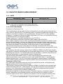
1
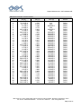
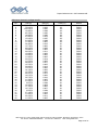
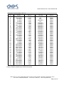
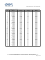
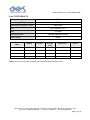
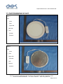
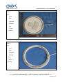
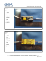
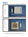
Report Reference No.: GST1406300410E TABLE OF CONTENTS 1 TEST CERTIFICATION .................................................................................................. 4 2 TEST RESULT SUMMARY ............................................................................................ 5 3 EUT DESCRIPTION ....................................................................................................... 6 4. TEST INSTRUMENTS ................................................................................................... 7 5. TEST METHODOLOGY ................................................................................................ 8 5.1. DECISION OF FINAL TEST MODE......................................................................................8 5.2. EUT SYSTEM OPERATION .................................................................................................8 6. SETUP OF EQUIPMENT UNDER TEST ....................................................................... 9 6.1. DESCRIPTION OF SUPPORT UNITS..................................................................................9 6.2. CONFIGURATION OF SYSTEM UNDER TEST ..................................................................9 7. FACILITIES AND ACCREDITATIONS.................................................................... 10 7.1. FACILITIES .........................................................................................................................10 7.2. ACCREDITATIONS ............................................................................................................10 7.3. MEASUREMENT UNCERTAINTY......................................................................................10 8 EMISSION TEST .......................................................................................................... 11 8.1. CONDUCTED EMISSION MEASUREMENT......................................................................11 8.1.1. LIMITS .................................................................................................................. 11 8.1.2. TEST PROCEDURES ........................................................................................... 11 8.1.3. TEST SETUP .........................................................................................................12 8.1.4. TEST RESULTS ....................................................................................................12 8.2. RADIATED ELECTROMAGNETIC DISTURBANCE ..........................................................15 8.2.1. LIMITS ..................................................................................................................15 8.2.2. TEST PROCEDURE..............................................................................................15 8.2.3. TEST SETUP .........................................................................................................16 8.2.4.TEST RESULTS .....................................................................................................16 8.3. RADIATED EMISSION MEASUREMENT...........................................................................20 8.3.1. LIMITS ..................................................................................................................20 8.3.2. TEST PROCEDURE..............................................................................................20 8.3.3. TEST SETUP .........................................................................................................21 8.3.4 TEST RESULTS .....................................................................................................21 8.4. HARMONICS CURRENT MEASUREMENT.......................................................................24 8.4.1. LIMITS OF HARMONICS CURRENT MEASUREMENT ................................24 8.4.2. TEST PROCEDURE..............................................................................................24 8.4.3. TEST SETUP .........................................................................................................25 8.4.4. TEST RESULTS ....................................................................................................25 8.5. VOLTAGE FLUCTUATION AND FLICKS MEASUREMENT ..............................................32 8.5.1. LIMITS OF VOLTAGE FLUCTUATION AND FLICKS MEASUREMENT .....32 8.5.2. TEST PROCEDURE..............................................................................................32 8.5.3. TEST SETUP .........................................................................................................32 8.5.4. TEST RESULTS ....................................................................................................32 Add: Room 1911-1914, Noble Plaza, Qian Jin Road 1st, Bao An district, Shenzhen, Guangdong, China Tel: 86-755--33863798/33863599 Fax: 86-755- 33863718 Web: www.gstslab.com Page 2 of 61 Report Reference No.: GST1406300410E 9. IMMUNITY TEST ......................................................................................................... 34 9.1. GENERAL DESCRIPTION .................................................................................................34 9.2. GENERAL PERFORMANCE CRITERIA DESCRIPTION...................................................35 9.3. ELECTROSTATIC DISCHARGE (ESD) .............................................................................35 9.3.1. TEST SPECIFICATION ........................................................................................35 9.3.2. TEST PROCEDURE..............................................................................................36 9.3.3. TEST SETUP .........................................................................................................37 9.3.4. TEST RESULTS ....................................................................................................38 9.4. RADIATED, RADIO-FREQUENCY, ELECTROMAGNETIC FIELD (RS) ...........................39 9.4.1. TEST SPECIFICATION ........................................................................................39 9.4.2. TEST PROCEDURE..............................................................................................39 9.4.3. TEST SETUP .........................................................................................................40 9.4.4. TEST RESULTS ....................................................................................................41 9.5. ELECTRICAL FAST TRANSIENT (EFT) ............................................................................42 9.5.1. TEST SPECIFICATION ........................................................................................42 9.5.2. TEST PROCEDURE..............................................................................................42 9.5.3. TEST SETUP .........................................................................................................43 9.5.4. TEST RESULTS ....................................................................................................44 9.6. SURGE IMMUNITY TEST ..................................................................................................45 9.6.1TEST SPECIFICATION ..........................................................................................45 9.6.2. TEST PROCEDURE..............................................................................................45 9.6.3. TEST SETUP .........................................................................................................46 9.6.4. TEST RESULTS ....................................................................................................46 9.7. CONDUCTED RADIO FREQUENCY DISTURBANCES (CS)............................................47 9.7.1. TEST SPECIFICATION ........................................................................................47 8.7.2. TEST PROCEDURE..............................................................................................47 9.7.3. TEST SETUP .........................................................................................................48 9.7.4. TEST RESULTS ....................................................................................................48 9.8. POWER FREQUENCY MAGNETIC FIELD ........................................................................49 9.8.1. TEST SPECIFICATION ........................................................................................49 9.8.2. TEST PROCEDURE..............................................................................................49 9.8.3. TEST SETUP .........................................................................................................50 9.8.4. TEST RESULTS ....................................................................................................51 9.9. VOLTAGE DIP & VOLTAGE INTERRUPTIONS.................................................................51 8.9.1. TEST SPECIFICATION ........................................................................................51 9.9.2. TEST PROCEDURE..............................................................................................52 9.9.3. TEST SETUP .........................................................................................................52 9.9.4. TEST RESULTS ....................................................................................................53 10. TEST SETUP PHOTOGRAPHS ................................................................................ 54 11. PHOTOGRAPHS OF EUT ......................................................................................... 55 Add: Room 1911-1914, Noble Plaza, Qian Jin Road 1st, Bao An district, Shenzhen, Guangdong, China Tel: 86-755--33863798/33863599 Fax: 86-755- 33863718 Web: www.gstslab.com Page 3 of 61 Report Reference No.: GST1406300410E 2 TEST RESULT SUMMARY EMISSION Item Standard Result Remarks Conducted (Main Port) PASS Meet limit Radiated Electromagnetic Disturbance PASS Meet limit Radiated PASS Meet limit EN 61000-3-2:2006+A1:2009 +A2:2009 Harmonic current emissions PASS Meet limit EN 61000-3-3:2008 Voltage fluctuations & flicker PASS Meet limit EN 55015:2006+A1:2007 +A2:2009 IMMUNITY【EN 61547:2009】 Standard Item Result Remarks ESD PASS Meets the requirements of Performance Criterion B EN 61000-4-3:2006+A1:2008 +A2:2010 RS PASS Meets the requirements of Performance Criterion A EN 61000-4-4:2004/A1:2010 EFT PASS Meets the requirements of Performance Criterion B EN 61000-4-5:2006 Surge PASS Meets the requirements of Performance Criterion B EN 61000-4-6:2009 CS PASS Meets the requirements of Performance Criterion A EN 61000-4-8: 2009 PFMF EN 61000-4-11:2004 Voltage dips & voltage variations EN 61000-4-2:2009 Note: PASS Meets the requirements Meets the requirements of Voltage dips and variations PASS 1) 30% reduction performance Criterion C 2)100% reduction performance Criterion B 1. The test result judgment is decided by the limit of test standard 2. The information of measurement uncertainty is available upon the customer’s request. Add: Room 1911-1914, Noble Plaza, Qian Jin Road 1st, Bao An district, Shenzhen, Guangdong, China Tel: 86-755--33863798/33863599 Fax: 86-755- 33863718 Web: www.gstslab.com Page 5 of 61 Report Reference No.: GST1406300410E 3 EUT DESCRIPTION Product LED PANEL LIGHT Model VT-2800 Applicant V-TAC EXPORTS LIMITED Housing material Plastic & Metal EUT Type Serial Number Engineering Sample. Mass Product Sample. Product Sample, N/A EUT Power Rating AC230V, 50Hz, 36W Max. AC Line N/A Add: Room 1911-1914, Noble Plaza, Qian Jin Road 1st, Bao An district, Shenzhen, Guangdong, China Tel: 86-755--33863798/33863599 Fax: 86-755- 33863718 Web: www.gstslab.com Page 6 of 61 Report Reference No.: GST1406300410E 4. TEST INSTRUMENTS Immunity shielded room Name of Equipment Manufacturer Model Serial Number EMC PARTNER TRANSIENT 2000 EMC PARTNER TRA2000 881 09/27/2014 Power-frequency Magnetic field SCHAFFNER CCN 1000-1 72046 09/27/2014 Induction Coil Interface SCHAFFNER INA2141 6003 09/27/2014 Signal Generator Maconi 2022D 119246/003 09/27/2014 Power Amplifier M2S A00181-1000 9801-112 09/27/2014 CDN MEB M3-8016 003683 09/27/2014 Power Amplifier M2S AC8113/ 800-250A 9801-179 09/27/2014 Power Antenna SCHAFFNER CBL6140A 1204 09/27/2014 ESD 2000 EMC PARTNER ESD2000 182 09/27/2014 Harmonic & Flicker Tester California instruments PACS-3 SB2588/01 09/27/2014 AC Power Source California instruments 5001iX-CTS-40 SB2588 09/27/2014 EMI Test Receiver R&S ESCI 100005 09/27/2014 Spectrum Analyzer R&S FSU 100114 09/27/2014 Pre Amplifier H.P. HP8447E 2945A02715 09/27/2014 Bilog Antenna SUNOL Sciences JB3 A021907 09/27/2014 Cable TIME MICROWAVE LMR-400 N-TYPE04 09/27/2014 System-Controller CCS N/A N/A N.C.R Turn Table CCS N/A N/A N.C.R CCS N/A N/A N.C.R EVERFINE LLA-2 N/A 09/27/2014 AFJ LS16 16010222119 09/27/2014 Mestec AN3016 04/10040 09/27/2014 Antenna Tower Triple-Loop Antenna LISN LISN(EUT) Calibration Due NOTE: (1) The calibration interval of the above test instruments is 12 months and the calibrations are traceable to international system unit (SI). (2). N.C.R = No Calibration Request. Add: Room 1911-1914, Noble Plaza, Qian Jin Road 1st, Bao An district, Shenzhen, Guangdong, China Tel: 86-755--33863798/33863599 Fax: 86-755- 33863718 Web: www.gstslab.com Page 7 of 61 Report Reference No.: GST1406300410E 5. TEST METHODOLOGY 5.1. DECISION OF FINAL TEST MODE The EUT was tested together with the thereinafter additional components, and a configuration, which produced the worst emission levels, was selected and recorded in this report. The following test mode(s) were scanned during the preliminary test: Pre-Test Mode Emission Conducted Emission Radiated Electromagnetic Disturbance Radiated Emission Immunity Mode: no Mode: N/A Mode: no Mode: no After the preliminary scan, the following test mode was found to produce the highest emission level. The Worst Mode Emission Conducted Emission Radiated Electromagnetic Disturbance Radiated Emission Immunity Mode: no Mode: N/A Mode: no Mode: no 5.2. EUT SYSTEM OPERATION 1. 2. Set up EUT with the support equipments. Make sure the EUT work normally during the test. Add: Room 1911-1914, Noble Plaza, Qian Jin Road 1st, Bao An district, Shenzhen, Guangdong, China Tel: 86-755--33863798/33863599 Fax: 86-755- 33863718 Web: www.gstslab.com Page 8 of 61 Report Reference No.: GST1406300410E 6. SETUP OF EQUIPMENT UNDER TEST 6.1. DESCRIPTION OF SUPPORT UNITS The EUT has been tested as an independent unit together with other necessary accessories or support units. The following support units or accessories were used to form a representative test configuration during the tests. No. Equipment Model No. Serial No. FCC ID Trade Name Data Cable Power Cord 1. N/A N/A N/A N/A N/A N/A N/A Note: 1)All the equipment/cables were placed in the worst-case configuration to maximize the emission during the test. 2)Grounding was established in accordance with the manufacturer’s requirements and conditions for the intended use. 6.2. CONFIGURATION OF SYSTEM UNDER TEST AC Mains EUT (EUT: LED PANEL LIGHT) Add: Room 1911-1914, Noble Plaza, Qian Jin Road 1st, Bao An district, Shenzhen, Guangdong, China Tel: 86-755--33863798/33863599 Fax: 86-755- 33863718 Web: www.gstslab.com Page 9 of 61 Report Reference No.: GST1406300410E 7. FACILITIES AND ACCREDITATIONS 7.1. FACILITIES The sites are constructed in conformance with the requirements of ANSI C63.4 and CISPR Publication 15. All receiving equipment conforms to CISPR Publication 16-1, “Radio Interference Measuring Apparatus and Measurement Methods.” 7.2. ACCREDITATIONS 7.3. MEASUREMENT UNCERTAINTY Where relevant, the following measurement uncertainty levels have been estimated for tests performed on the EUT as specified in CISPR 16-4-2: Measurement Frequency Uncertainty Conducted emissions 9kHz~30MHz +/- 3.59dB Radiated electromagnetic 9kHz~30MHz +/- 4.77dB 30MHz ~ 200MHz +/- 4.77dB Horizontal 200MHz ~1000MHz +/- 4.93dB Radiated emissions 30MHz ~ 200MHz +/- 5.04dB Vertical 200MHz ~1000MHz +/- 4.93dB This uncertainty represents an expanded uncertainty expressed at approximately the 95% confidence level using a coverage factor of k=2. Add: Room 1911-1914, Noble Plaza, Qian Jin Road 1st, Bao An district, Shenzhen, Guangdong, China Tel: 86-755--33863798/33863599 Fax: 86-755- 33863718 Web: www.gstslab.com Page 10 of 61 Report Reference No.: GST1406300410E 8 EMISSION TEST 8.1. CONDUCTED EMISSION MEASUREMENT 8.1.1. LIMITS FREQUENCY (MHz) LIMITS(dBuV) Quasi-peak Average 0.009-0.05 110 N/A 0.05-0.15 90 – 80 N/A 0.15 – 0.5 66 – 56 56 – 46 0.50 – 5.0 56 46 5.0 – 30.0 60 50 NOTE: (1) The lower limit shall apply at the transition frequencies. (2) The limit decreases in line with the logarithm of the frequency in the range of 0.15 to 0.50 MHz. (3) All emanations from EUT or system, shall not exceed the level of field strengths specified above. 8.1.2. TEST PROCEDURES Procedure of Preliminary Test The EUT and Support equipment, if needed, was set up as per the test configuration to simulate typical usage per the user’s manual. When the EUT is a tabletop system, a wooden table with a height of 0.8 meters is used and is placed on the ground plane. When the EUT is a floor standing equipment, it is placed on the ground plane, which has a 3-12 mm non-conductive covering to insulate the EUT from the ground plane. The EUT test program was started. Emissions were measured on each current carrying line of the EUT using an EMI Test Receiver connected to the LISN powering the EUT. The Receiver scanned from 9 kHz to 30MHz for emissions in each of the test modes. During the above scans, the emissions were maximized by cable manipulation. The test mode(s) described in Item 3.1 were scanned during the preliminary test. After the preliminary scan, we found the test mode described in Item 3.1 producing the highest emission level. The EUT configuration and cable configuration of the above highest emission levels were recorded for reference of the final test. Procedure of Final Test EUT and support equipment were set up on the test bench as per the configuration with highest emission level in the preliminary test. A scan was taken on both power lines, Line 1 and Line 2, recording at least the six highest emissions. Emission frequency and amplitude were recorded into a computer in which correction factors were used to calculate the emission level and compare reading to the applicable limit. The test data of the worst-case condition(s) was recorded. Add: Room 1911-1914, Noble Plaza, Qian Jin Road 1st, Bao An district, Shenzhen, Guangdong, China Tel: 86-755--33863798/33863599 Fax: 86-755- 33863718 Web: www.gstslab.com Page 11 of 61 Report Reference No.: GST1406300410E 8.1.3. TEST SETUP Vert. reference plane EMI receiver 40cm EUT 80cm LISN Reference ground plane For the actual test configuration, please refer to the related item – Photographs of the Test Configuration. 8.1.4. TEST RESULTS Temperature ( ℃ ) 22~28 Humidity ( %RH ) 50~58 Barometric Pressure ( mbar ) 950~1000 EUT LED PANEL LIGHT M/N VT-2800 Operating Mode Test Results Normal Operation Mode PASS Please refer to following diagram for individual Add: Room 1911-1914, Noble Plaza, Qian Jin Road 1st, Bao An district, Shenzhen, Guangdong, China Tel: 86-755--33863798/33863599 Fax: 86-755- 33863718 Web: www.gstslab.com Page 12 of 61 Report Reference No.: GST1406300410E EUT: Temperature: Pressure: Test Mode : Test Power : 1 2 3 4 5 6 7 8 LED PANEL LIGHT 24 ℃ 1010 hPa On AC230V 50Hz Model Name : VT-2800 Relative Humidity:54% Test Date : July 07, 2014 Polarization : L Freq. (MHz) Reading (dBuV) Factor (dBuV) Measurement (dBuV) Limit (dBuV) Over (dB) Detector 0.1700 0.4300 0.8660 0.9540 1.5540 1.5540 2.0740 2.1580 30.33 27.64 28.28 39.81 38.19 26.28 36.79 24.53 10.45 10.41 10.41 10.42 10.42 10.42 10.42 10.42 40.78 38.05 38.69 50.22 48.61 36.70 47.21 34.95 54.96 47.25 46.00 56.00 56.00 46.00 56.00 46.00 -14.18 -9.20 -7.31 -5.78 -7.39 -9.30 -8.79 -11.05 AV AV AV QP QP AV QP AV Remark: 1. All readings are Quasi-Peak and Average values. 2. Factor = Insertion Loss + Cable Loss. 3. N/A means All Data have pass Limit Add: Room 1911-1914, Noble Plaza, Qian Jin Road 1st, Bao An district, Shenzhen, Guangdong, China Tel: 86-755--33863798/33863599 Fax: 86-755- 33863718 Web: www.gstslab.com Page 13 of 61 Report Reference No.: GST1406300410E EUT: Temperature: Pressure: Test Mode : Test Power : 1 2 3 4 5 6 7 LED PANEL LIGHT 24 ℃ 1010 hPa On AC230V 50Hz Model Name : VT-2800 Relative Humidity:54% Test Date : July 07, 2014 Polarization : N Freq. (MHz) Reading (dBuV) Factor (dBuV) Measurement (dBuV) Limit (dBuV) Over (dB) Detector 0.2580 0.8620 0.8620 1.4620 1.4620 2.0579 2.7540 34.01 41.50 28.69 39.82 36.61 38.14 23.37 10.43 10.43 10.43 10.45 10.45 10.44 10.46 44.44 51.93 39.12 50.27 37.06 48.58 33.83 51.49 56.00 46.00 56.00 46.00 56.00 46.00 -7.05 -4.07 -6.88 -5.73 -8.94 -7.42 -12.17 AV QP AV QP AV QP AV Remark: 1. All readings are Quasi-Peak and Average values. 2. Factor = Insertion Loss + Cable Loss. 3. N/A means All Data have pass Limit Add: Room 1911-1914, Noble Plaza, Qian Jin Road 1st, Bao An district, Shenzhen, Guangdong, China Tel: 86-755--33863798/33863599 Fax: 86-755- 33863718 Web: www.gstslab.com Page 14 of 61 Report Reference No.: GST1406300410E 8.2. RADIATED ELECTROMAGNETIC DISTURBANCE 8.2.1. LIMITS Frequency Limits for loop diameter dB(uA)* 2m 3m 4m 9KHz-70KHz 88 81 75 70KHz-150KHz 88-58** 81-51** 75-45** 150KHz-3.0MHz 58-22** 51-22** 45-16** 3.0MHz-30MHz 22 15-16*** 9-12*** * At the transition frequency, the lower limit applies. ** Decreasing linearly with the logarithm of the frequency. *** Increasing linearly with the logarithm of the frequency. Note: In Japan, the limits for frequencies 9KHz to 150KHz do not apply. 8.2.2. TEST PROCEDURE In the frequency range 9KHz to 30MHz the interference capability of the magnetic field component of the radiation of Equipment Under Test (EUT) can be determined by using a special Loop Antenna System (LAS). In the LAS, this capability is measured in terms of the currents induced by the magnetic field in the loop antennas of the LAS. The LAS allows indoor measurement. The LAS consists of three circular, mutually perpendicular Large-Loop Antennas (LLAs), having a diameter of 2 m, supported by a non-metallic base. A 50Ω coaxial cable between the current probe of an LLA and the coaxial switch, and between this switch and the measuring equipment, shall have a surface transfer impedance smaller than 10mΩ/m at 100KHz and 1mΩ/m at 10MHz. The distance between the outer diameter of the loop antenna system and nearby objects, such as floor and walls, shall be at least 0.5m as per CISPR 15/ EN55015. The EUT is positioned in the center of the LAS (To avoid unwanted capacitive coupling between the EUT and the LAS, the maximum dimensions of the EUT are limited so that the distance between the EUT and an LLA is at least 0.2m). Cables should be routed together and leave the loop volume in the same octant of the cell, no closer than 0.4m to the LAS loops. The induced current in the loop antenna is measured by means of a current probe(1V/A) and the CISPR measuring receiver(or equivalent). By means of a coaxial switch, the three field direction(X, Y, Z) can be measured in sequence, and recorded at least the six highest emission. Each value shall fulfill the requirement given. The test data of the worst-case condition(s) was recorded. Add: Room 1911-1914, Noble Plaza, Qian Jin Road 1st, Bao An district, Shenzhen, Guangdong, China Tel: 86-755--33863798/33863599 Fax: 86-755- 33863718 Web: www.gstslab.com Page 15 of 61 Report Reference No.: GST1406300410E 8.2.3. TEST SETUP For the actual test configuration, please refer to the related item – Photographs of the Test Configuration. 8.2.4.TEST RESULTS Temperature ( ℃ ) 22~28 Humidity ( %RH ) 50~58 Barometric Pressure ( mbar ) 950~1000 EUT LED PANEL LIGHT M/N VT-2800 Operating Mode Test Results Normal Operation Mode PASS Add: Room 1911-1914, Noble Plaza, Qian Jin Road 1st, Bao An district, Shenzhen, Guangdong, China Tel: 86-755--33863798/33863599 Fax: 86-755- 33863718 Web: www.gstslab.com Page 16 of 61 Report Reference No.: GST1406300410E EUT: Temperature: Pressure: Test Mode : Test Power : 1 2 3 4 5 LED PANEL LIGHT 24 ℃ 1010 hPa On AC230V 50Hz Model Name : VT-2800 Relative Humidity:54% Test Date : July 07, 2014 Polarization : X Freq. (MHz) Reading (dBuV) Factor (dBuV) Measurement (dBuV) Limit (dBuV) Over (dB) Detector 0.0154 0.0308 0.1499 1.374 16.7137 67.02 42.42 22.79 13.37 9.07 4.3 6.1 2 0.8 1 71.32 48.52 24.79 14.17 10.07 88 88 58 31.61 22 -16.68 -39.48 -33.21 -17.44 -11.93 QP QP QP QP QP Remark: 1. All readings are Quasi-Peak and Average values. 2. Factor = Antenna Factor + Cable Loss - Amplifier. 3. N/A means All Data have pass Limit Add: Room 1911-1914, Noble Plaza, Qian Jin Road 1st, Bao An district, Shenzhen, Guangdong, China Tel: 86-755--33863798/33863599 Fax: 86-755- 33863718 Web: www.gstslab.com Page 17 of 61 Report Reference No.: GST1406300410E EUT: Temperature: Pressure: Test Mode : Test Power : 1 2 3 4 LED PANEL LIGHT 24 ℃ 1010 hPa On AC230V 50Hz Model Name : VT-2800 Relative Humidity:54% Test Date : July 07, 2014 Polarization : Y Freq. (MHz) Reading (dBuV) Factor (dBuV) Measurement (dBuV) Limit (dBuV) Over (dB) Detector 0.0308 0.1502 1.4336 5.2819 38.92 20.53 14.58 11.03 6.1 1.96 0.8 1 45.02 22.49 15.38 12.03 88 57.98 31.1 22 -42.98 -35.49 -15.72 -9.97 QP QP QP QP Remark: 1. All readings are Quasi-Peak and Average values. 2. Factor = Antenna Factor + Cable Loss - Amplifier. 3. N/A means All Data have pass Limit Add: Room 1911-1914, Noble Plaza, Qian Jin Road 1st, Bao An district, Shenzhen, Guangdong, China Tel: 86-755--33863798/33863599 Fax: 86-755- 33863718 Web: www.gstslab.com Page 18 of 61 Report Reference No.: GST1406300410E EUT: Temperature: Pressure: Test Mode : Test Power : 1 2 3 4 5 LED PANEL LIGHT 24 ℃ 1010 hPa On AC230V 50Hz Model Name : VT-2800 Relative Humidity:54% Test Date : July 07, 2014 Polarization : Z Freq. (MHz) Reading (dBuV) Factor (dBuV) Measurement (dBuV) Limit (dBuV) Over (dB) Detector 0.0154 0.0229 0.0308 0.1499 1.4858 61.52 43.5 42.42 19.79 10.71 4.3 3.28 6.1 2 0.8 65.82 46.78 48.52 21.79 11.51 88 88 88 58 30.68 -22.18 -41.22 -39.48 -36.21 -19.17 QP QP QP QP QP Remark: 1. All readings are Quasi-Peak and Average values. 2. Factor = Antenna Factor + Cable Loss - Amplifier. 3. N/A means All Data have pass Limit Add: Room 1911-1914, Noble Plaza, Qian Jin Road 1st, Bao An district, Shenzhen, Guangdong, China Tel: 86-755--33863798/33863599 Fax: 86-755- 33863718 Web: www.gstslab.com Page 19 of 61 Report Reference No.: GST1406300410E 8.3. RADIATED EMISSION MEASUREMENT 8.3.1. LIMITS FREQUENCY (MHz) dBuV/m (At 3m) 30 ~ 230 40 230 ~ 300 47 NOTE: (1) The lower limit shall apply at the transition frequencies. (2) Emission level (dBuV/m) = 20 log Emission level (uV/m). 8.3.2. TEST PROCEDURE Procedure of Preliminary Test The equipment was set up as per the test configuration to simulate typical usage per the user’s manual. When the EUT is a tabletop system, a wooden turntable with a height of 0.8 meters is used which is placed on the ground plane. When the EUT is a floor standing equipment, it is placed on the ground plane which has a 3-12 mm non-conductive covering to insulate the EUT from the ground plane. Support equipment, if needed, was placed as per EN 55015. All I/O cables were positioned to simulate typical usage as per EN 55015. Mains cables, telephone lines or other connections to auxiliary equipment located outside the test are shall drape to the floor, be fitted with ferrite clamps or ferrite tubes placed on the floor at the point where the cable reaches the floor and then routed to the place where they leave the turntable. No extension cords shall be used to mains receptacle. The antenna was placed at 3 meter away from the EUT as stated in EN 55015. The antenna connected to the Spectrum Analyzer via a cable and at times a pre-amplifier would be used. The Analyzer / Receiver quickly scanned from 30MHz to 300MHz. The EUT test program was started. Emissions were scanned and measured rotating the EUT to 360 degrees and positioning the antenna 1 to 4 meters above the ground plane, in both the vertical and the horizontal polarization, to maximize the emission reading level. The test mode(s) described in Item 3.1 were scanned during the preliminary test: After the preliminary scan, we found the test mode described in Item 3.1 producing the highest emission level. The EUT and cable configuration, antenna position, polarization and turntable position of the above highest emission level were recorded for the final test. Procedure of Final Test EUT and support equipment were set up on the turntable as per the configuration with highest emission level in the preliminary test. The Analyzer / Receiver scanned from 30MHz to 300MHz. Emissions were scanned and measured rotating the EUT to 360 degrees, varying cable placement and positioning the antenna 1 to 4 meters above the ground plane, in both the vertical and the horizontal polarization, to maximize the emission reading level. Recorded at least the six highest emissions. Emission frequency, amplitude, antenna position, polarization and turntable position were recorded into a computer in which correction factors were used to calculate the emission level and compare reading to the Add: Room 1911-1914, Noble Plaza, Qian Jin Road 1st, Bao An district, Shenzhen, Guangdong, China Tel: 86-755--33863798/33863599 Fax: 86-755- 33863718 Web: www.gstslab.com Page 20 of 61 Report Reference No.: GST1406300410E applicable limit and only Q.P. reading is presented. The test data of the worst-case condition(s) was recorded. 8.3.3. TEST SETUP Test table & Turntable 1m ~ 4m EUT Coaxial Cable Power Cable 0.8 m 3m Filter Filter Ground Plane To Power EMI Receiver For the actual test configuration, please refer to the related item – Photographs of the Test Configuration. 8.3.4 TEST RESULTS Temperature ( ℃ ) 22~28 Humidity ( %RH ) 50~58 Barometric Pressure ( mbar ) 950~1000 EUT LED PANEL LIGHT M/N VT-2800 Operating Mode Test Results EUT: LED PANEL LIGHT Temperature: 24 ℃ Normal Operation Mode PASS Model Name : VT-2800 Relative Humidity:54% Add: Room 1911-1914, Noble Plaza, Qian Jin Road 1st, Bao An district, Shenzhen, Guangdong, China Tel: 86-755--33863798/33863599 Fax: 86-755- 33863718 Web: www.gstslab.com Page 21 of 61 Report Reference No.: GST1406300410E Pressure: Test Mode : Test Power : 1010 hPa On AC230V 50Hz Freq. (MHz) 1 30.0692 2 54.9694 3 92.9226 4 139.9978 Test Date : Polarization : July 07, 2014 Vertical Reading (dBuV) Factor (dBuV) Measurement (dBuV) Limit (dBuV) Over (dB) Detector 15.40 22.54 17.38 23.33 18.30 6.09 9.75 11.93 33.70 28.63 27.13 35.26 40.00 40.00 40.00 40.00 -6.30 -11.37 -12.87 -4.74 QP QP QP QP Remark: 1. All readings are Quasi-Peak and Average values. 2. Factor = Insertion Loss + Cable Loss. 3. N/A means All Data have pass Limit Add: Room 1911-1914, Noble Plaza, Qian Jin Road 1st, Bao An district, Shenzhen, Guangdong, China Tel: 86-755--33863798/33863599 Fax: 86-755- 33863718 Web: www.gstslab.com Page 22 of 61 Report Reference No.: GST1406300410E EUT: Temperature: Pressure: Test Mode : Test Power : 1 2 3 LED PANEL LIGHT 24 ℃ 1010 hPa On AC230V 50Hz Model Name : VT-2800 Relative Humidity:54% Test Date : July 07, 2014 Polarization : Horizontal Freq. (MHz) Reading (dBuV) Factor (dBuV) Measurement (dBuV) Limit (dBuV) Over (dB) Detector 139.3546 224.9683 265.5347 12.82 18.68 21.33 11.93 10.28 13.84 24.75 28.96 35.17 40.00 40.00 47.00 -15.25 -11.04 -11.83 QP QP QP Remark: 1. All readings are Quasi-Peak and Average values. 2. Factor = Insertion Loss + Cable Loss. 3. N/A means All Data have pass Limit Add: Room 1911-1914, Noble Plaza, Qian Jin Road 1st, Bao An district, Shenzhen, Guangdong, China Tel: 86-755--33863798/33863599 Fax: 86-755- 33863718 Web: www.gstslab.com Page 23 of 61 Report Reference No.: GST1406300410E 8.4. HARMONICS CURRENT MEASUREMENT 8.4.1. LIMITS OF HARMONICS CURRENT MEASUREMENT Limits for Class A equipment Harmonics Max. permissible Order harmonics current n A Odd harmonics 3 2.30 5 1.14 7 0.77 9 0.40 11 0.33 13 0.21 15<=n<=39 0.15x15/n Even harmonics 2 1.08 4 0.43 6 0.30 8<=n<=40 0.23x8/n Harmonics Order n 3 5 7 9 11 13 15<=n<=39 Limits for Class D equipment Max. permissible Max. permissible harmonics harmonics current current per watt mA/W A Odd Harmonics only 3.4 2.30 1.9 1.14 1.0 0.77 0.5 0.40 0.35 0.33 0.30 0.21 3.85/n 0.15x15/n NOTE: 1. Class A and Class D are classified according to item 4.4.3. 2. According to section 7 of EN 61000-3-2, the above limits apply for all equipments with a rated power more than 75W, except for lighting equipment. 8.4.2. TEST PROCEDURE The EUT was placed on the top of a wooden table 0.8 meters above the ground and operated to produce the maximum harmonic components under LIGHTING operating conditions for each successive harmonic component in turn. The classification of EUT is according to section 5 of EN 61000-3-2. The EUT is classified as follows: Class A: Balanced three-phase equipment, Household appliances excluding equipment as Class D, Tools excluding portable tools, Dimmers for incandescent lamps, audio equipment, equipment not specified in one of the three other classes. Class B: Portable tools; Arc welding equipment which is not professional equipment. Class C: Lighting equipment. Class D: Equipment having a specified power less than or equal to 600 W of the following types: Personal computers and personal computer monitors and television receivers. Add: Room 1911-1914, Noble Plaza, Qian Jin Road 1st, Bao An district, Shenzhen, Guangdong, China Tel: 86-755--33863798/33863599 Fax: 86-755- 33863718 Web: www.gstslab.com Page 24 of 61 Report Reference No.: GST1406300410E The correspondent test program of test instrument to measure the current harmonics emanated from EUT is chosen. The measure time shall be not less than the time necessary for the EUT to be exercised. 8.4.3. TEST SETUP Harmonics & Flicker Analyzer + Power Source Power EUT Support Units 0.8m For the actual test configuration, please refer to the related item. 8.4.4. TEST RESULTS Temperature ( ℃ ) 22~28 Humidity ( %RH ) 50~58 Barometric Pressure ( mbar ) 950~1000 EUT LED PANEL LIGHT M/N VT-2800 Operating Mode Test Results Normal Operation Mode PASS Add: Room 1911-1914, Noble Plaza, Qian Jin Road 1st, Bao An district, Shenzhen, Guangdong, China Tel: 86-755--33863798/33863599 Fax: 86-755- 33863718 Web: www.gstslab.com Page 25 of 61 Report Reference No.: GST1406300410E E. U. T. Result Harmonic(s) > 200%: Order (n): None Harmonic(s) with average > 90%: Order (n): None Harmonic(s) between 150% and 200% during more than 10% of the test time or max. 10min: Order (n): None Power Source Result First dataset out of limit: DS (time): None Harmonic(s) out of limit: Order (n): None Add: Room 1911-1914, Noble Plaza, Qian Jin Road 1st, Bao An district, Shenzhen, Guangdong, China Tel: 86-755--33863798/33863599 Fax: 86-755- 33863718 Web: www.gstslab.com Page 26 of 61 Report Reference No.: GST1406300410E Average harmonic current results Hn 1 2 3 4 5 6 7 8 9 10 11 12 13 14 15 16 17 18 19 20 21 22 23 24 25 26 27 28 29 30 31 32 33 34 35 36 37 38 39 40 Ieff [A] 92.234E-3 655.048E-6 10.276E-3 2.069E-3 4.270E-3 768.469E-6 1.351E-3 804.642E-6 1.488E-3 710.588E-6 1.008E-3 895.573E-6 1.778E-3 891.521E-6 1.102E-3 772.700E-6 1.266E-3 1.171E-3 909.143E-6 808.971E-6 1.163E-3 1.048E-3 1.459E-3 821.581E-6 832.532E-6 786.264E-6 1.054E-3 785.917E-6 779.776E-6 762.567E-6 1.101E-3 862.040E-6 816.708E-6 577.011E-6 881.679E-6 829.227E-6 621.672E-6 658.199E-6 609.231E-6 882.731E-6 Ieff [%] 100.000 0.710 11.142 2.244 4.630 0.833 1.465 0.872 1.613 0.770 1.093 0.971 1.928 0.967 1.195 0.838 1.372 1.270 0.986 0.877 1.261 1.136 1.581 0.891 0.903 0.852 1.142 0.852 0.845 0.827 1.194 0.935 0.885 0.626 0.956 0.899 0.674 0.714 0.661 0.957 Limit [A] Result 972.00E-3 2.07 387.00E-3 1.03 270.00E-3 693.00E-3 207.00E-3 360.00E-3 165.60E-3 297.00E-3 138.00E-3 189.00E-3 118.29E-3 135.00E-3 103.50E-3 119.11E-3 92.00E-3 106.58E-3 82.80E-3 96.43E-3 75.28E-3 88.05E-3 68.99E-3 81.00E-3 63.69E-3 75.00E-3 59.14E-3 69.83E-3 55.20E-3 65.32E-3 51.75E-3 61.36E-3 48.71E-3 57.86E-3 46.00E-3 54.73E-3 43.58E-3 51.92E-3 41.40E-3 PASS PASS PASS PASS PASS PASS PASS PASS PASS PASS PASS PASS PASS PASS PASS PASS PASS PASS PASS PASS PASS PASS PASS PASS PASS PASS PASS PASS PASS PASS PASS PASS PASS PASS PASS PASS PASS PASS PASS Add: Room 1911-1914, Noble Plaza, Qian Jin Road 1st, Bao An district, Shenzhen, Guangdong, China Tel: 86-755--33863798/33863599 Fax: 86-755- 33863718 Web: www.gstslab.com Page 27 of 61 Report Reference No.: GST1406300410E Maximum harmonic current results Hn 1 2 3 4 5 6 7 8 9 10 11 12 13 14 15 16 17 18 19 20 21 22 23 24 25 26 27 28 29 30 31 32 33 34 35 36 37 38 39 40 Ieff [A] 92.748E-3 727.927E-6 10.739E-3 2.219E-3 4.428E-3 865.163E-6 1.516E-3 949.202E-6 1.592E-3 807.329E-6 1.144E-3 1.011E-3 1.871E-3 1.021E-3 1.188E-3 895.833E-6 1.357E-3 1.279E-3 1.010E-3 957.397E-6 1.309E-3 1.160E-3 1.551E-3 913.210E-6 980.837E-6 872.214E-6 1.164E-3 866.918E-6 874.169E-6 821.839E-6 1.226E-3 1.001E-3 889.147E-6 702.045E-6 1.056E-3 1.049E-3 683.656E-6 720.106E-6 704.946E-6 962.540E-6 Ieff [%] 100.000 0.785 11.579 2.392 4.775 0.933 1.634 1.023 1.716 0.870 1.233 1.090 2.017 1.101 1.281 0.966 1.463 1.379 1.089 1.032 1.412 1.250 1.672 0.985 1.058 0.940 1.255 0.935 0.943 0.886 1.321 1.080 0.959 0.757 1.138 1.131 0.737 0.776 0.760 1.038 Limit [A] Result 2.16 4.60 860.00E-3 2.28 600.00E-3 1.54 460.00E-3 800.00E-3 368.00E-3 660.00E-3 306.66E-3 420.00E-3 262.86E-3 300.00E-3 230.00E-3 264.70E-3 204.44E-3 236.84E-3 184.00E-3 214.28E-3 167.28E-3 195.66E-3 153.32E-3 180.00E-3 141.54E-3 166.66E-3 131.42E-3 155.18E-3 122.66E-3 145.16E-3 115.00E-3 136.36E-3 108.24E-3 128.58E-3 102.22E-3 121.62E-3 96.84E-3 115.38E-3 92.00E-3 PASS PASS PASS PASS PASS PASS PASS PASS PASS PASS PASS PASS PASS PASS PASS PASS PASS PASS PASS PASS PASS PASS PASS PASS PASS PASS PASS PASS PASS PASS PASS PASS PASS PASS PASS PASS PASS PASS PASS Add: Room 1911-1914, Noble Plaza, Qian Jin Road 1st, Bao An district, Shenzhen, Guangdong, China Tel: 86-755--33863798/33863599 Fax: 86-755- 33863718 Web: www.gstslab.com Page 28 of 61 Report Reference No.: GST1406300410E Maximum harmonic voltage results Hn 1 2 3 4 5 6 7 8 9 10 11 12 13 14 15 16 17 18 19 20 21 22 23 24 25 26 27 28 29 30 31 32 33 34 35 36 37 38 39 40 Ueff [V] 231.34 75.91E-3 105.53E-3 19.46E-3 46.33E-3 14.92E-3 27.95E-3 15.24E-3 21.85E-3 11.40E-3 34.46E-3 12.73E-3 46.01E-3 10.98E-3 26.03E-3 13.69E-3 12.56E-3 11.05E-3 32.97E-3 11.27E-3 38.02E-3 10.70E-3 30.86E-3 13.61E-3 14.13E-3 12.75E-3 24.97E-3 14.51E-3 36.73E-3 11.32E-3 31.84E-3 9.87E-3 18.26E-3 11.12E-3 16.71E-3 9.52E-3 27.14E-3 11.82E-3 25.43E-3 11.20E-3 Ueff [%] 100.581 0.033 0.046 0.008 0.020 0.006 0.012 0.007 0.009 0.005 0.015 0.006 0.020 0.005 0.011 0.006 0.005 0.005 0.014 0.005 0.017 0.005 0.013 0.006 0.006 0.006 0.011 0.006 0.016 0.005 0.014 0.004 0.008 0.005 0.007 0.004 0.012 0.005 0.011 0.005 Limit [%] 0.2 0.9 0.2 0.4 0.2 0.3 0.2 0.2 0.2 0.1 0.1 0.1 0.1 0.1 0.1 0.1 0.1 0.1 0.1 0.1 0.1 0.1 0.1 0.1 0.1 0.1 0.1 0.1 0.1 0.1 0.1 0.1 0.1 0.1 0.1 0.1 0.1 0.1 0.1 Result PASS PASS PASS PASS PASS PASS PASS PASS PASS PASS PASS PASS PASS PASS PASS PASS PASS PASS PASS PASS PASS PASS PASS PASS PASS PASS PASS PASS PASS PASS PASS PASS PASS PASS PASS PASS PASS PASS PASS Add: Room 1911-1914, Noble Plaza, Qian Jin Road 1st, Bao An district, Shenzhen, Guangdong, China Tel: 86-755--33863798/33863599 Fax: 86-755- 33863718 Web: www.gstslab.com Page 29 of 61 Report Reference No.: GST1406300410E Harmonic current results - DS: 12 Hn 1 2 3 4 5 6 7 8 9 10 11 12 13 14 15 16 17 18 19 20 21 22 23 24 25 26 27 28 29 30 31 32 33 34 35 36 37 38 39 40 Ieff [A] 92.712E-3 704.608E-6 10.639E-3 2.139E-3 4.299E-3 832.811E-6 1.445E-3 884.116E-6 1.363E-3 763.749E-6 875.233E-6 972.537E-6 1.856E-3 979.993E-6 1.026E-3 839.819E-6 1.220E-3 1.218E-3 904.638E-6 936.464E-6 1.018E-3 1.055E-3 1.318E-3 860.203E-6 935.082E-6 854.993E-6 994.117E-6 829.497E-6 780.429E-6 734.336E-6 1.049E-3 887.986E-6 759.486E-6 613.586E-6 1.038E-3 693.755E-6 652.006E-6 679.788E-6 625.308E-6 874.345E-6 Ieff [%] 100.000 0.760 11.475 2.307 4.636 0.898 1.559 0.954 1.470 0.824 0.944 1.049 2.001 1.057 1.106 0.906 1.316 1.314 0.976 1.010 1.098 1.138 1.422 0.928 1.009 0.922 1.072 0.895 0.842 0.792 1.131 0.958 0.819 0.662 1.120 0.748 0.703 0.733 0.674 0.943 Limit [A] Result 1.08 2.30 430.00E-3 1.14 300.00E-3 770.00E-3 230.00E-3 400.00E-3 184.00E-3 330.00E-3 153.33E-3 210.00E-3 131.43E-3 150.00E-3 115.00E-3 132.35E-3 102.22E-3 118.42E-3 92.00E-3 107.14E-3 83.64E-3 97.83E-3 76.66E-3 90.00E-3 70.77E-3 83.33E-3 65.71E-3 77.59E-3 61.33E-3 72.58E-3 57.50E-3 68.18E-3 54.12E-3 64.29E-3 51.11E-3 60.81E-3 48.42E-3 57.69E-3 46.00E-3 PASS PASS PASS PASS PASS PASS PASS PASS PASS PASS PASS PASS PASS PASS PASS PASS PASS PASS PASS PASS PASS PASS PASS PASS PASS PASS PASS PASS PASS PASS PASS PASS PASS PASS PASS PASS PASS PASS PASS Caution: Results related to the 100% limit values Add: Room 1911-1914, Noble Plaza, Qian Jin Road 1st, Bao An district, Shenzhen, Guangdong, China Tel: 86-755--33863798/33863599 Fax: 86-755- 33863718 Web: www.gstslab.com Page 30 of 61 Report Reference No.: GST1406300410E Harmonic voltage results - DS: 12 Hn 1 2 3 4 5 6 7 8 9 10 11 12 13 14 15 16 17 18 19 20 21 22 23 24 25 26 27 28 29 30 31 32 33 34 35 36 37 38 39 40 Ueff [V] 231.31 60.54E-3 70.76E-3 12.76E-3 43.49E-3 9.52E-3 11.86E-3 9.42E-3 6.10E-3 2.47E-3 28.26E-3 7.73E-3 34.07E-3 4.93E-3 22.34E-3 7.46E-3 7.60E-3 3.05E-3 27.28E-3 6.86E-3 26.25E-3 2.17E-3 26.23E-3 6.31E-3 11.13E-3 3.71E-3 15.02E-3 2.47E-3 26.57E-3 7.69E-3 21.76E-3 2.83E-3 12.78E-3 2.58E-3 7.26E-3 2.74E-3 19.96E-3 7.82E-3 18.18E-3 4.23E-3 Ueff [%] 100.571 0.026 0.031 0.006 0.019 0.004 0.005 0.004 0.003 0.001 0.012 0.003 0.015 0.002 0.010 0.003 0.003 0.001 0.012 0.003 0.011 0.001 0.011 0.003 0.005 0.002 0.007 0.001 0.012 0.003 0.009 0.001 0.006 0.001 0.003 0.001 0.009 0.003 0.008 0.002 Limit [%] 0.2 0.9 0.2 0.4 0.2 0.3 0.2 0.2 0.2 0.1 0.1 0.1 0.1 0.1 0.1 0.1 0.1 0.1 0.1 0.1 0.1 0.1 0.1 0.1 0.1 0.1 0.1 0.1 0.1 0.1 0.1 0.1 0.1 0.1 0.1 0.1 0.1 0.1 0.1 Result PASS PASS PASS PASS PASS PASS PASS PASS PASS PASS PASS PASS PASS PASS PASS PASS PASS PASS PASS PASS PASS PASS PASS PASS PASS PASS PASS PASS PASS PASS PASS PASS PASS PASS PASS PASS PASS PASS PASS Add: Room 1911-1914, Noble Plaza, Qian Jin Road 1st, Bao An district, Shenzhen, Guangdong, China Tel: 86-755--33863798/33863599 Fax: 86-755- 33863718 Web: www.gstslab.com Page 31 of 61 Report Reference No.: GST1406300410E 8.5. VOLTAGE FLUCTUATION AND FLICKS MEASUREMENT 8.5.1. LIMITS OF VOLTAGE FLUCTUATION AND FLICKS MEASUREMENT TEST ITEM LIMIT Pst Plt Tdt (ms) dmax (%) dc (%) 1.0 0.65 500 4% 3.3% REMARK Pst means short-term flicker indicator. Plt means long-term flicker indicator. Tdt means maximum time that dt exceeds 3 %. dmax means maximum relative voltage change. dc means relative steady-state voltage change 8.5.2. TEST PROCEDURE The EUT was placed on the top of a wooden table 0.8 meters above the ground and operated to produce the most unfavorable sequence of voltage changes under LIGHTING operating conditions. During the flick measurement, the measure time shall include that part of whole operation cycle in which the EUT produce the most unfavorable sequence of voltage changes. The observation period for short-term flicker indicator is 10 minutes and the observation period for long-term flicker indicator is 2 hours. 8.5.3. TEST SETUP Harmonics & Flicker Analyzer + Power Source Power EUT Support Units 0.8m For the actual test configuration, please refer to the related item. 8.5.4. TEST RESULTS Temperature ( ℃ ) 22~28 Add: Room 1911-1914, Noble Plaza, Qian Jin Road 1st, Bao An district, Shenzhen, Guangdong, China Tel: 86-755--33863798/33863599 Fax: 86-755- 33863718 Web: www.gstslab.com Page 32 of 61 Report Reference No.: GST1406300410E Humidity ( %RH ) 50~58 Barometric Pressure ( mbar ) 950~1000 EUT LED PANEL LIGHT M/N VT-2800 Operating Mode Normal Operation Mode Test Results PASS Maximum Flicker results EUT values Limit Result Pst 0.028 1.00 PASS Plt 0.028 0.65 PASS dc [%] 0.005 3.30 PASS dmax [%] 0.269 4.00 PASS dt [s] 0.000 0.50 PASS Add: Room 1911-1914, Noble Plaza, Qian Jin Road 1st, Bao An district, Shenzhen, Guangdong, China Tel: 86-755--33863798/33863599 Fax: 86-755- 33863718 Web: www.gstslab.com Page 33 of 61 Report Reference No.: GST1406300410E 9. IMMUNITY TEST 9.1. GENERAL DESCRIPTION EN 61547: 2009 Product Standard Test Type EN61000-4-2:2009 Minimum Requirement Electrostatic Discharge – ESD: 8kV air discharge, 4kV Contact discharge, Performance Criterion B Radio-Frequency Electromagnetic Field EN61000-4-3:2006+A1:2008 Susceptibility Test – RS: 80 ~1000 MHz, 3V/m, 80% AM(1kHz), +A2:2010 Performance Criterion A Electrical Fast Transient/Burst - EFT, EN61000-4-4:2004/A1:2010 Power line: 1kV, Signal line: 0.5kV, Performance Criterion B Basic Standard, Specification, and EN61000-4-5:2006 Performance Criterion required Surge Immunity Test: 1.2/50 us Open Circuit Voltage, 8 /20 us Short Circuit Current, Power Port ~ Line to line: 0.5kV, Line to ground: 1kV ( to self-ballasted lamps and semi-luminaries;luminaires and independent auxiliaries which are less than 25W) Power Port ~ Line to line: 1kV, Line to ground: 2kV (to luminaires and independent auxiliaries which are more than 25W) Signal Port : 0.5kV Performance Criterion B EN61000-4-6:2009 Conducted Radio Frequency Disturbances Test –CS: 0.15 ~ 80 MHz, 3Vrms, 80% AM, 1kHz, Performance Criterion A EN61000-4-8: 2009 Power frequency magnetic field immunity test 50 Hz, 3A/m Performance Criterion A EN61000-4-11:2004 Voltage Dips and Interruptions: ii) 30% reduction for 10 period, Performance Criterion C 100% reduction for 0.5 period Performance Criterion B Add: Room 1911-1914, Noble Plaza, Qian Jin Road 1st, Bao An district, Shenzhen, Guangdong, China Tel: 86-755--33863798/33863599 Fax: 86-755- 33863718 Web: www.gstslab.com Page 34 of 61 Report Reference No.: GST1406300410E 9.2. GENERAL PERFORMANCE CRITERIA DESCRIPTION Criteria A: During the test no change of the luminous intensity shall be observed and the regulating control, if any, shall operate during the test as intended. Criteria B: During the test the luminous intensity may change to any value. After the test the luminous intensity shall be restored to its initial value within 1 min. Regulating controls need not function during the test, but after the test the mode of the control shall be the same as before the test provided that during the test no mode changing commands were given. Criteria C: During and after the test any change of the luminous intensity is allowed and the lamp(s) may be extinguished. After the test, within 30 min, all functions shall return to T5 LED PANEL LIGHT if necessary by temporary interruption of the mains supply and/or operating the regulating control. Additional requirement for lighting equipment incorporating a starting device: After the test the lighting equipment is switched off. After half an hour it is switched on again. The lighting equipment shall start and operate as intended. 9.3. ELECTROSTATIC DISCHARGE (ESD) 9.3.1. TEST SPECIFICATION Basic Standard: Discharge Impedance: Charging Capacity: Discharge Voltage: Polarity: Number of Discharge: Discharge Mode: Performance Criterion: EN 61000-4-2 330ohm 150pF Air Discharge: 8 kV (Direct) Contact Discharge: 4 kV (Direct/Indirect) Positive & Negative Minimum 10 times at each test point 1 time/s B Add: Room 1911-1914, Noble Plaza, Qian Jin Road 1st, Bao An district, Shenzhen, Guangdong, China Tel: 86-755--33863798/33863599 Fax: 86-755- 33863718 Web: www.gstslab.com Page 35 of 61 Report Reference No.: GST1406300410E 9.3.2. TEST PROCEDURE The discharges shall be applied in two ways: a) Contact discharges to the conductive surfaces and coupling planes: Twenty dischargers (10 with positive and 10 with negative polarity) shall be applied on each accessible metallic part of the enclosure, terminals are excluded. In case of a non-conductive enclosure, dischargers shall be applied on the horizontal or vertical coupling planes. Test shall be performed at a maximum repetition rate of one discharge per second. b) Air discharges at slots and apertures and insulating surfaces: On those parts of the EUT where it is not possible to perform contact discharge testing, the equipment should be investigated to identify user accessible points where breakdown may occur. Such points are tested using the air discharge method. This investigation should be restricted to those area normally handled by the user. A minimum of 10 single air discharges shall be applied to the selected test point for each such area. The basic test procedure was in accordance with IEC 61000-4-2: a) The EUT was located 0.1 m minimum from all side of the HCP (dimensions 1.6m x 0.8m). b) The support units were located another table 30 cm away from the EUT, but direct support unit was/were located at same location as EUT on the HCP and keep at a distance of 10 cm with EUT. c) The time interval between two successive single discharges was at least 1 second. d) Contact discharges were applied to the non-insulating coating, with the pointed tip of the generator penetrating the coating and contacting the conducting substrate. e) Air discharges were applied with the round discharge tip of the discharge electrode approaching the EUT as fast as possible (without causing mechanical damage) to touch the EUT. After each discharge, the ESD generator was removed from the EUT and re-triggered for a new single discharge. The test was repeated until all discharges were complete. f) At least ten single discharges (in the most sensitive polarity) were applied at the front edge of each HCP opposite the center point of each unit of the EUT and 0.1 meters from the front of the EUT. The long axis of the discharge electrode was in the plane of the HCP and perpendicular to its front edge during the discharge. g) At least ten single discharges (in the most sensitive polarity) were applied to the center of one vertical edge of the Vertical Coupling Plane (VCP) in sufficiently different positions that the four faces of the EUT were completely illuminated. The VCP (dimensions 0.5m x 0.5m) was placed vertically to and 0.1 meters from the EUT. Add: Room 1911-1914, Noble Plaza, Qian Jin Road 1st, Bao An district, Shenzhen, Guangdong, China Tel: 86-755--33863798/33863599 Fax: 86-755- 33863718 Web: www.gstslab.com Page 36 of 61 Report Reference No.: GST1406300410E 9.3.3. TEST SETUP VCP EUT & Support Units Support units HCP >1m Wooden 0.8m Ground Reference For the actual test configuration, please refer to the related item – Photographs of the Test Configuration. NOTE: TABLE-TOP EQUIPMENT The configuration consisted of a wooden table 0.8 meters high standing on the Ground Reference Plane. The GRP consisted of a sheet of aluminum at least 0.25mm thick, and 2.5 meters square connected to the protective grounding system. A Horizontal Coupling Plane (1.6m x 0.8m) was placed on the table and attached to the GRP by means of a cable with 940k total impedance. The equipment under test, was installed in a representative system as described in section 7 of EN 61000-4-2, and its cables were placed on the HCP and isolated by an insulating support of 0.5mm thickness. A distance of 1-meter minimum was provided between the EUT and the walls of the laboratory and any other metallic structure. FLOOR-STANDING EQUIPMENT The equipment under test was installed in a representative system as described in section 7 of IEC 61000-4-2, and its cables were isolated from the Ground Reference Plane by an insulating support of 0.1-meter thickness. The GRP consisted of a sheet of aluminum that is at least 0.25mm thick, and 2.5 meters square connected to the protective grounding system and extended at least 0.5 meters from the EUT on all sides. Add: Room 1911-1914, Noble Plaza, Qian Jin Road 1st, Bao An district, Shenzhen, Guangdong, China Tel: 86-755--33863798/33863599 Fax: 86-755- 33863718 Web: www.gstslab.com Page 37 of 61 Report Reference No.: GST1406300410E 9.3.4. TEST RESULTS Temperature ( ℃ ) 22~28 Humidity ( %RH ) 50~58 Barometric Pressure ( mbar ) 950~1000 EUT LED PANEL LIGHT M/N VT-2800 Operating Mode Normal Operation Mode Test Results PASS Air Discharge Test Levels Test Points 8 kV Results Pass Fail Performance Criterion Observation Slots 6Points B Note 1 2 Port 2Points B Note 1 2 Contact Discharge Test Levels Test Points Metal HCP VCP 4Points 4Points 4Points 4 kV Results Pass Fail Performance Criterion B B B Observation Note Note Note 1 1 1 2 2 2 NOTE: 1. There was no change compared with initial operation during the test. 2. The loss of function of the EUT during the test and it was recovered by itself operation after the test. Add: Room 1911-1914, Noble Plaza, Qian Jin Road 1st, Bao An district, Shenzhen, Guangdong, China Tel: 86-755--33863798/33863599 Fax: 86-755- 33863718 Web: www.gstslab.com Page 38 of 61 Report Reference No.: GST1406300410E 9.4. RADIATED, RADIO-FREQUENCY, ELECTROMAGNETIC FIELD (RS) 9.4.1. TEST SPECIFICATION Basic Standard: Frequency Range: Field Strength: Modulation: Frequency Step: Polarity of Antenna: Test Distance: Antenna Height: Performance Criterion: EN 61000-4-3 80 MHz ~1000 MHz, 3 V/m 1kHz Sine Wave, 80%, AM Modulation 1 % of preceding frequency value Horizontal and Vertical 3m 1.5m A 9.4.2. TEST PROCEDURE The test procedure was in accordance with EN 61000-4-3 a) The testing was performed in a fully anechoic chamber. The transmit antenna was located at a distance of 3 meters from the EUT. b) The frequency range is swept from 80 MHz to 1000 MHz, with the signal 80% amplitude modulated with a 1 kHz sine-wave. The rate of sweep did not exceed 1.5 x 10 -3 decade/s, where the frequency range is swept incrementally; the step size was 1% of preceding frequency value. c) The dwell time at each frequency shall be not less than the time necessary for the EUT to be able to respond. d) The test was performed with the EUT exposed to both vertically and horizontally polarized fields on each of the four sides. Add: Room 1911-1914, Noble Plaza, Qian Jin Road 1st, Bao An district, Shenzhen, Guangdong, China Tel: 86-755--33863798/33863599 Fax: 86-755- 33863718 Web: www.gstslab.com Page 39 of 61 Report Reference No.: GST1406300410E 9.4.3. TEST SETUP 3m 7X4X3 EUT& Support i 0.8m Power Amp Signal EUT Monitoring by Generator using a camera PC Controller to control S.G. & PA as well as forward power Control Room For the actual test configuration, please refer to the related item. NOTE: TABLETOP EQUIPMENT The EUT installed in a representative system as described in section 7 of EN 61000-4-3 was placed on a non-conductive table 0.8 meters in height. The system under test was connected to the power and signal wire according to relevant installation instructions. FLOOR STANDING EQUIPMENT The EUT installed in a representative system as described in section 7 of IEC 61000-4-3 was placed on a non-conductive wood support 0.1 meters in height. The system under test was connected to the power and signal wire according to relevant installation instructions. Add: Room 1911-1914, Noble Plaza, Qian Jin Road 1st, Bao An district, Shenzhen, Guangdong, China Tel: 86-755--33863798/33863599 Fax: 86-755- 33863718 Web: www.gstslab.com Page 40 of 61 Report Reference No.: GST1406300410E 9.4.4. TEST RESULTS Temperature ( ℃ ) 22~28 Humidity ( %RH ) 50~58 Barometric Pressure ( mbar ) 950~1000 EUT LED PANEL LIGHT M/N VT-2800 Operating Mode Normal Operation Mode Test Results PASS Frequency (MHz) Polarity Position Field Strength (V/m) Observation Result 80 ~ 1000 V&H Front 3 Note PASS 80 ~ 1000 V&H Rear 3 Note PASS 80 ~ 1000 V&H Left 3 Note PASS 80 ~ 1000 V&H Right 3 Note PASS NOTE: There was no change compared with the initial operation during the test. Add: Room 1911-1914, Noble Plaza, Qian Jin Road 1st, Bao An district, Shenzhen, Guangdong, China Tel: 86-755--33863798/33863599 Fax: 86-755- 33863718 Web: www.gstslab.com Page 41 of 61 Report Reference No.: GST1406300410E 9.5. ELECTRICAL FAST TRANSIENT (EFT) 9.5.1. TEST SPECIFICATION Basic Standard: Test Voltage: Polarity: Impulse Frequency: Impulse Wave-shape: Burst Duration: Burst Period: Test Duration: Performance Criterion: EN 61000-4-4 Power Line: 1 kV Signal/Control Line: 0.5 kV Positive & Negative 5 kHz 5/50 ns 15 ms 300ms Not less than 1 min. B 9.5.2. TEST PROCEDURE a) Both positive and negative polarity discharges were applied. b) The length of the “hot wire” from the coaxial output of the EFT generator to the terminals on the EUT should not exceed 1 meter. c) The duration time of each test sequential was 1 minute. d) The transient/burst waveform was in accordance with EN 61000-4-4, 5/50ns. Add: Room 1911-1914, Noble Plaza, Qian Jin Road 1st, Bao An district, Shenzhen, Guangdong, China Tel: 86-755--33863798/33863599 Fax: 86-755- 33863718 Web: www.gstslab.com Page 42 of 61 Report Reference No.: GST1406300410E 9.5.3. TEST SETUP EUT AC EFT/Burst/ Surge Generator 0.8m Support Units Non-Conductive Table Controller Computer Comm. Line ≧ 3 m To Load EUT 10cm Non-Conductive Table AC Burst Generator 0.8m Injection Clamp For the actual test configuration, please refer to the related item – Photographs of the Test Configuration. NOTE: TABLETOP EQUIPMENT The configuration consisted of a wooden table (0.8m high) standing on the Ground Reference Plane. The GRP consisted of a sheet of aluminum (at least 0.25mm thick and 2.5m square) connected to the protective grounding system. A minimum distance of 0.5m was provided between the EUT and the walls of the laboratory or any other metallic structure. FLOOR STANDING EQUIPMENT The EUT installed in a representative system as described in section 7 of IEC 61000-4-4 and its cables, were isolated from the Ground Reference Plane by an insulating support that is 0.1-meter thick. The GRP consisted of a sheet of aluminum (at least 0.25mm thick and 2.5m square) connected to the protective grounding system. Add: Room 1911-1914, Noble Plaza, Qian Jin Road 1st, Bao An district, Shenzhen, Guangdong, China Tel: 86-755--33863798/33863599 Fax: 86-755- 33863718 Web: www.gstslab.com Page 43 of 61 Report Reference No.: GST1406300410E 9.5.4. TEST RESULTS Temperature ( ℃ ) 22~28 Humidity ( %RH ) 50~58 Barometric Pressure ( mbar ) 950~1000 EUT LED PANEL LIGHT M/N VT-2800 Operating Mode Normal Operation Mode Test Results PASS Test Point Polarity Test Level (kV) Performance Criterion L1 +/- 1 B Note 1 2 PASS L2 +/- 1 B Note 1 2 PASS L 1–L 2 +/- 1 B Note 1 2 PASS PE +/- 1 B Note 1 2 PASS L – PE +/- 1 B Note 1 2 PASS N – PE +/- 1 B Note 1 2 PASS L – N – PE +/- 1 B Note 1 2 PASS RJ45 UTP cable -- -- -- Note 1 2 N/A Observation Result NOTE: 1. There was no change compared with initial operation during the test. 2. The loss of function of the EUT during the test and it was recovered by itself operation after the test. Add: Room 1911-1914, Noble Plaza, Qian Jin Road 1st, Bao An district, Shenzhen, Guangdong, China Tel: 86-755--33863798/33863599 Fax: 86-755- 33863718 Web: www.gstslab.com Page 44 of 61 Report Reference No.: GST1406300410E 9.6. SURGE IMMUNITY TEST 9.6.1TEST SPECIFICATION Basic Standard: EN 61000-4-5 Wave-Shape: Combination Wave 1.2/50 us Open Circuit Voltage 8/20 us Short Circuit Current Power line ~ line to line: 1 kV; Test Voltage: line to ground: 2kV Telecommunication line: 1 kV; Surge Input/Output: Power Line: L1-L2 / L1-PE / L2-PE Telecommunication line: T-Ground / R-Ground Generator Source Impedance: 2 ohm between networks 12 ohm between network and ground Polarity: Positive/Negative Phase Angle: 0 /90 /180 /270 Pulse Repetition Rate: 1 time / min. (maximum) Number of Tests: 5 positive and 5 negative at selected points Performance Criterion: B 9.6.2. TEST PROCEDURE a) For EUT power supply: The surge is applied to the EUT power supply terminals via the capacitive coupling network. Decoupling networks are required in order to avoid possible adverse effects on equipment not under test that may be powered by the same lines, and to provide sufficient decoupling impedance to the surge wave. The power cord between the EUT and the coupling/decoupling networks was shorter than 2 meters in length. b) For test applied to unshielded un-symmetrically operated interconnection lines of EUT: The surge was applied to the lines via the capacitive coupling. The coupling / decoupling networks didn’t influence the specified functional conditions of the EUT. The interconnection line between the EUT and the coupling/decoupling networks was shorter than 2 meters in length. c) For test applied to unshielded symmetrically operated interconnection / telecommunication lines of EUT: The surge was applied to the lines via gas arrestors coupling. Test levels below the ignition point of the coupling arrestor were not specified. The interconnection line between the EUT and the coupling/decoupling networks was shorter than 2 meters in length. Add: Room 1911-1914, Noble Plaza, Qian Jin Road 1st, Bao An district, Shenzhen, Guangdong, China Tel: 86-755--33863798/33863599 Fax: 86-755- 33863718 Web: www.gstslab.com Page 45 of 61 Report Reference No.: GST1406300410E 9.6.3. TEST SETUP To AC Source Surge Immunity Test EUT & Support Units 0.8m Controller Computer For the actual test configuration, please refer to the related item – Photographs of the Test Configuration. 9.6.4. TEST RESULTS Temperature ( ℃ ) 22~28 Humidity ( %RH ) 50~58 Barometric Pressure ( mbar ) 950~1000 EUT LED PANEL LIGHT M/N VT-2800 Operating Mode Normal Operation Mode Test Results PASS Test Point Polarity Test Level (kV) Performance Criterion L1-L2 +/- 1 B Note 1 2 PASS L1 - PE +/- 2 B Note 1 2 PASS L2 - PE +/- 2 B Note 1 2 PASS R - Ground -- -- -- Note 1 2 N/A T - Ground -- -- -- Note 1 2 N/A Observation Result NOTE: 1. There was no change compared with initial operation during the test. 2. The loss of function of the EUT during the test and it was recovered by itself operation after the test. Add: Room 1911-1914, Noble Plaza, Qian Jin Road 1st, Bao An district, Shenzhen, Guangdong, China Tel: 86-755--33863798/33863599 Fax: 86-755- 33863718 Web: www.gstslab.com Page 46 of 61 Report Reference No.: GST1406300410E 9.7. CONDUCTED RADIO FREQUENCY DISTURBANCES (CS) 9.7.1. TEST SPECIFICATION Basic Standard: Frequency Range: Field Strength: Modulation: Frequency Step: Coupled cable: Coupling device: Performance Criterion: EN 61000-4-6 0.15 MHz ~ 80 MHz 3V 1kHz Sine Wave, 80%, AM Modulation 1 % of preceding frequency value Power Mains, Shielded CDN-M3/2 (3 wires) A 8.7.2. TEST PROCEDURE The EUT shall be tested within its intended operating and climatic conditions. The test shell performed with the test generator connected to each of the coupling and decoupling devices in turn, while the other non-excited RF input ports of the coupling devices are terminated by a 50-ohm load resistor. The frequency range was swept from 150 kHz to 80 MHz, using the signal level established during the setting process and with a disturbance signal of 80 % amplitude. The signal was modulated with a 1 kHz sine wave, pausing to adjust the RF signal level or the switch coupling devices as necessary. The sweep rate was 1.5 x 10⁻³ decades/s. Where the frequency range is swept incrementally, the step size was 1 % of preceding frequency value from 150 kHz to 80 MHz. The dwell time at each frequency was less than the time necessary for the EUT to be exercised, and able to respond. Sensitive frequencies such as clock frequency(ies) and harmonics or frequencies of dominant interest, was analyzed separately. Attempts was made to fully exercise the EUT during testing, and to fully interrogate all exercise modes selected for susceptibility. Add: Room 1911-1914, Noble Plaza, Qian Jin Road 1st, Bao An district, Shenzhen, Guangdong, China Tel: 86-755--33863798/33863599 Fax: 86-755- 33863718 Web: www.gstslab.com Page 47 of 61 Report Reference No.: GST1406300410E 9.7.3. TEST SETUP 10 cm isolation supporter Power PC Amplifier Controller 0.1m< L <0.3m EUT and Support units CDN Note: 1. The EUT is setup 0.1m above Ground Reference Plane 2. The CDNS and / or EM clamp used for real test depends on ports and cables configuration of EUT. For the actual test configuration, please refer to the related item. NOTE: TABLE-TOP AND FLOOR-STANDING EQUIPMENT The equipment to be tested is placed on an insulating support of 0.1 meters height above a ground reference plane. All relevant cables shall be provided with the appropriate coupling and decoupling devices at a distance between 0.1 meters and 0.3 meters from the projected geometry of the EUT on the ground reference plane. 9.7.4. TEST RESULTS Temperature ( ℃ ) 22~28 Humidity ( %RH ) 50~58 Barometric Pressure ( mbar ) 950~1000 EUT LED PANEL LIGHT M/N VT-2800 Operating Mode Normal Operation Mode Test Results PASS Field Frequency Strength Band (MHz) (Vrms) Injected Position Injection Method Performance Criterion CDN-M3 A 0.15 ~ 80 3 AC Mains 0.15 ~ 80 3 N/A Result Observation Note 1 2 3 Note 1 2 N/A NOTE: 1. There was no change compared with initial operation during the test. 2. The loss of function of the EUT during the test and it was recovered by itself operation after the test. Add: Room 1911-1914, Noble Plaza, Qian Jin Road 1st, Bao An district, Shenzhen, Guangdong, China Tel: 86-755--33863798/33863599 Fax: 86-755- 33863718 Web: www.gstslab.com Page 48 of 61 Report Reference No.: GST1406300410E 9.8. POWER FREQUENCY MAGNETIC FIELD 9.8.1. TEST SPECIFICATION Basic Standard: Frequency Range: Field Strength: Observation Time: Inductance Coil: Performance Criterion: EN 61000-4-8 50Hz, 3A/m 5 minutes Rectangular type, 1mx1m A 9.8.2. TEST PROCEDURE a) The equipment is configured and connected to satisfy its functional requirements. It shall be placed on the GRP with the interposition of a 0.1m-thick insulating support. b. The equipment cabinets shall be connected to the safety earth directly on the GRP via the earth terminal of the EUT. c. The power supply, input and output circuits shall be connected to the sources of power supply, control and signal. d. The cables supplied or recommended by the equipment manufacturer shall be used. 1 meter of all cables used shall be exposed to the magnetic field. Add: Room 1911-1914, Noble Plaza, Qian Jin Road 1st, Bao An district, Shenzhen, Guangdong, China Tel: 86-755--33863798/33863599 Fax: 86-755- 33863718 Web: www.gstslab.com Page 49 of 61 Report Reference No.: GST1406300410E 9.8.3. TEST SETUP Induction Coil 1/2 Dimension of EUT EUT Signal Generator To Earth Ground For the actual test configuration, please refer to the related item. NOTE: TABLETOP EQUIPMENT The equipment shall be subjected to the test magnetic field by using the induction coil of standard dimension (1 m x 1 m). The induction coil shall then be rotated by 90 degrees in order to expose the EUT to the test field with different orientations. FLOOR-STANDING EQUIPMENT The equipment shall be subjected to the test magnetic field by using induction coils of suitable dimensions. The test shall be repeated by moving and shifting the induction coils, in order to test the whole volume of the EUT for each orthogonal direction. The test shall be repeated with the coil shifted to different positions along the side of the EUT, in steps corresponding to 50 % of the shortest side of the coil. The induction coil shall then be rotated by 90 degrees in order to expose the EUT to the test field with different orientations. Add: Room 1911-1914, Noble Plaza, Qian Jin Road 1st, Bao An district, Shenzhen, Guangdong, China Tel: 86-755--33863798/33863599 Fax: 86-755- 33863718 Web: www.gstslab.com Page 50 of 61 Report Reference No.: GST1406300410E 9.8.4. TEST RESULTS Temperature ( ℃ ) 22~28 Humidity ( %RH ) 50~58 Barometric Pressure ( mbar ) 950~1000 EUT LED PANEL LIGHT M/N VT-2800 Operating Mode Normal Operation Mode Test Results PASS DIRECTION Field Strength (A/m) Performance Criterion X 3 A Note 1 2 PASS Y 3 A Note 1 2 PASS Z 3 A Note 1 2 PASS OBSERVATION RESULTS NOTE: 1. There was no change compared with initial operation during the test. 2. The loss of function of the EUT during the test and it was recovered by itself operation after the test. 3. This item is tested by Shenzhen Aacademy of Metrology & Quality Inspection 9.9. VOLTAGE DIP & VOLTAGE INTERRUPTIONS 8.9.1. TEST SPECIFICATION Basic Standard: Test Duration Time: Interval Between Event: Phase Angle: Test Cycle: Performance Criterion: EN 61000-4-11 Minimum three test events in sequence Minimum 10 seconds 0 / 45 / 90 / 135 / 180 / 225 / 270 / 315 / 360 3 times B,C Add: Room 1911-1914, Noble Plaza, Qian Jin Road 1st, Bao An district, Shenzhen, Guangdong, China Tel: 86-755--33863798/33863599 Fax: 86-755- 33863718 Web: www.gstslab.com Page 51 of 61 Report Reference No.: GST1406300410E 9.9.2. TEST PROCEDURE 1. 2. 3. 4. The EUT and support units were located on a wooden table, 0.8 m away from ground floor. Setting the parameter of tests and then perform the test software of test simulator. Conditions changes to occur at 0 degree crossover point of the voltage waveform. Recording the test result in test record form. 9.9.3. TEST SETUP For the actual test configuration, please refer to the related item – Photographs of the Test Configuration. To AC Source Dips/Interruption and Variations Simulator EUT & Support Units 0.8m Controller Computer Add: Room 1911-1914, Noble Plaza, Qian Jin Road 1st, Bao An district, Shenzhen, Guangdong, China Tel: 86-755--33863798/33863599 Fax: 86-755- 33863718 Web: www.gstslab.com Page 52 of 61 Report Reference No.: GST1406300410E 9.9.4. TEST RESULTS Temperature ( ℃ ) 22~28 Humidity ( %RH ) 50~58 Barometric Pressure ( mbar ) 950~1000 EUT LED PANEL LIGHT M/N VT-2800 Operating Mode Normal Operation Mode Test Results PASS Test Power: 230Vac, 50Hz Voltage (% Reduction) Duration (Period) 100 0.5 A B C Note 1 2 3 PASS 30 10 A B C Note 1 2 3 PASS Performance Criterion Test Result Observation NOTE: 1.There was no change compared with initial operation during and after the test. No unintentional response was found during the test. 2.The function stopped during the test, but can be recoverable by itself operation after the test. 3.The function stopped during the test, but can be recoverable manually after the test. Add: Room 1911-1914, Noble Plaza, Qian Jin Road 1st, Bao An district, Shenzhen, Guangdong, China Tel: 86-755--33863798/33863599 Fax: 86-755- 33863718 Web: www.gstslab.com Page 53 of 61 Report Reference No.: GST1406300410E 10. TEST SETUP PHOTOGRAPHS CONDUCTED EMISSION TEST RADIATED EMISSION TEST Add: Room 1911-1914, Noble Plaza, Qian Jin Road 1st, Bao An district, Shenzhen, Guangdong, China Tel: 86-755--33863798/33863599 Fax: 86-755- 33863718 Web: www.gstslab.com Page 54 of 61 Report Reference No.: GST1406300410E 11. PHOTOGRAPHS OF EUT Photo 1 View: [ ] front [ ] rear [ ] right side [ ] left side [√ ] top [ ] bottom [ ] internal Photo 2 View: [ ] front [√ ] rear [ ] right side [ ] left side [ ] top [ ] bottom [ ] internal Add: Room 1911-1914, Noble Plaza, Qian Jin Road 1st, Bao An district, Shenzhen, Guangdong, China Tel: 86-755--33863798/33863599 Fax: 86-755- 33863718 Web: www.gstslab.com Page 55 of 61 Report Reference No.: GST1406300410E Photo 3 View: [ ] front [ ] rear [ ] right side [ ] left side [ ] top [ ] bottom [√ ] internal Photo 4 View: [ ] front [ ] rear [ ] right side [ ] left side [ ] top [ ] bottom [√ ] internal Add: Room 1911-1914, Noble Plaza, Qian Jin Road 1st, Bao An district, Shenzhen, Guangdong, China Tel: 86-755--33863798/33863599 Fax: 86-755- 33863718 Web: www.gstslab.com Page 56 of 61 Report Reference No.: GST1406300410E Photo 5 View: [ ] front [ ] rear [ ] right side [ ] left side [ ] top [ ] bottom [√ ] internal Photo 6 View: [ ] front [ ] rear [ ] right side [ ] left side [ ] top [ ] bottom [√ ] internal Add: Room 1911-1914, Noble Plaza, Qian Jin Road 1st, Bao An district, Shenzhen, Guangdong, China Tel: 86-755--33863798/33863599 Fax: 86-755- 33863718 Web: www.gstslab.com Page 57 of 61 Report Reference No.: GST1406300410E Photo 7 View: [ ] front [ ] rear [ ] right side [ ] left side [√ ] top [ ] bottom [ ] internal Photo 8 View: [ ] front [√ ] rear [ ] right side [ ] left side [ ] top [ ] bottom [ ] internal Add: Room 1911-1914, Noble Plaza, Qian Jin Road 1st, Bao An district, Shenzhen, Guangdong, China Tel: 86-755--33863798/33863599 Fax: 86-755- 33863718 Web: www.gstslab.com Page 58 of 61 Report Reference No.: GST1406300410E Photo 9 View: [ ] front [ ] rear [ ] right side [ ] left side [√ ] top [ ] bottom [ ] internal Photo 10 View: [ ] front [√ ] rear [ ] right side [ ] left side [ ] top [ ] bottom [ ] internal Add: Room 1911-1914, Noble Plaza, Qian Jin Road 1st, Bao An district, Shenzhen, Guangdong, China Tel: 86-755--33863798/33863599 Fax: 86-755- 33863718 Web: www.gstslab.com Page 59 of 61 Report Reference No.: GST1406300410E Photo 11 View: [ ] front [ ] rear [ ] right side [ ] left side [√ ] top [ ] bottom [ ] internal Photo 12 View: [ ] front [√ ] rear [ ] right side [ ] left side [ ] top [ ] bottom [ ] internal Add: Room 1911-1914, Noble Plaza, Qian Jin Road 1st, Bao An district, Shenzhen, Guangdong, China Tel: 86-755--33863798/33863599 Fax: 86-755- 33863718 Web: www.gstslab.com Page 60 of 61 Report Reference No.: GST1406300410E Photo 13 View: [ ] front [ ] rear [ ] right side [ ] left side [√ ] top [ ] bottom [ ] internal Photo 14 View: [ ] front [√ ] rear [ ] right side [ ] left side [ ] top [ ] bottom [ ] internal END. Add: Room 1911-1914, Noble Plaza, Qian Jin Road 1st, Bao An district, Shenzhen, Guangdong, China Tel: 86-755--33863798/33863599 Fax: 86-755- 33863718 Web: www.gstslab.com Page 61 of 61