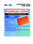
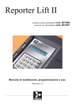
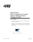
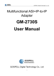
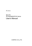
1
Shenzhen TCT Testing Technology Co., Ltd. Report No.: TCT11207230002ER TEST REPORT For Product: Plasma-positive and negative ions Trade Name: FUWEI Model: FUWEI/ARC-FLASH – 7K Report No.: Issued Date: TCT11207230002ER Jul.23, 2012 Issued for: FU WEI HIGH SCIENTIFIC CO . , LTD. No. 77, Lane 311, Nangong St., YonuKang City, Tainan County 710, Taiwan, R.O.C Issued By: Shenzhen TCT Testing Technology Co., Ltd. 11-12F, Henglin Building, Baoyuan Road, Xixiang Street, Baoan District, Shenzhen, Guangdong, China Note: This report shall not be reproduced except in full, without the written approval of Shenzhen TCT Testing Technology Co., Ltd. This document may be altered or revised by Shenzhen TCT Testing Technology Co., Ltd. personnel only, and shall be noted in the revision section of the document. The test results in the report only apply to the tested sample. Page 1 This report shall not be reproduced except in full, without the written approval of Shenzhen TCT Testing Technology Co., Ltd. Shenzhen TCT Testing Technology Co., Ltd. Report No.: TCT11207230002ER TABLE OF CONTENTS 1 TEST CERTIFICATION .................................................................................................. 3 2 TEST RESULT SUMMARY............................................................................................ 4 3 EUT DESCRIPTION ....................................................................................................... 5 4 TEST METHODOLOGY ................................................................................................. 6 4.1. DECISION OF FINAL TEST MODE...................................................................................... 6 4.2. EUT SYSTEM OPERATION ................................................................................................. 6 5 SETUP OF EQUIPMENT UNDER TEST........................................................................ 7 5.1. DESCRIPTION OF SUPPORT UNITS ................................................................................. 7 6 FACILITIES AND ACCREDITATIONS .......................................................................... 8 6.1. FACILITIES ........................................................................................................................... 8 6.2. ACCREDITATIONS .............................................................................................................. 8 6.3. MEASUREMENT UNCERTAINTY........................................................................................ 8 7 EMISSION TEST ........................................................................................................... 9 7.1. CONDUCTED EMISSION MEASUREMENT........................................................................ 9 7.2. DISTURBANCE POWER MEASUREMENT....................................................................... 14 8 IMMUNITY TEST .......................................................................................................... 18 8.1. GENERAL DESCRIPTION ................................................................................................. 18 8.2. GENERAL PERFORMANCE CRITERIA DESCRIPTION................................................... 19 8.3. ELECTROSTATIC DISCHARGE (ESD) ............................................................................. 20 8.4. ELECTRICAL FAST TRANSIENT (EFT) ............................................................................ 24 8.5. SURGE IMMUNITY TEST .................................................................................................. 27 8.6. CONDUCTED RADIO FREQUENCY DISTURBANCES (CS)............................................ 30 8.7. VOLTAGE DIP & VOLTAGE INTERRUPTIONS ................................................................ 33 9 PHOTOGRAPHS OF EUT............................................................................................ 35 Hotline: 400-6611-140 Tel: 86-755- 27673339 Fax: 86-755-27673332 Page 2 of 36 http://www.tct-lab.com. Shenzhen TCT Testing Technology Co., Ltd. Report No.: TCT11207230002ER 1 TEST CERTIFICATION Product: Plasma-positive and negative ions Trade Name: FUWEI Model: FUWEI/ARC-FLASH – 7K Applicant: FU WEI HIGH SCIENTIFIC CO . , LTD. No. 77, Lane 311, Nangong St., YonuKang City, Tainan County 710, Taiwan, R.O.C Manufacturer: FU WEI HIGH SCIENTIFIC CO . , LTD. No. 77, Lane 311, Nangong St., YonuKang City, Tainan County 710, Taiwan, R.O.C Tested: Jul.17 – Jul.23, 2012 Applicable EN 55014-1: 2006+A1:2009 Standards: EN 61000-3-2:2006+A1:2009 EN 61000-3-3:2008 EN 55014-2:1997+A1:2001+A2:2008 EN 61000-4-2:2009 EN 61000-4-3:2006+A1:2008+A2:2010 EN 61000-4-4:2004+A1:2010 EN 61000-4-5:2006 EN 61000-4-6:2009 EN 61000-4-11:2004 Deviation from Applicable Standard None The above equipment has been tested by Shenzhen TCT Testing Technology Co., Ltd. and found compliance with the requirements set forth in the technical standards mentioned above. The results of testing in this report apply only to the product/system, which was tested. Other similar equipment will not necessarily produce the same results due to production tolerance and measurement uncertainties. Tested By: Check By: Approved By: Date: Jul.23, 2012 Date: Jul.23, 2012 Date: Jul.23, 2012 (Tomsin) Hotline: 400-6611-140 Tel: 86-755- 27673339 Fax: 86-755-27673332 Page 3 of 36 http://www.tct-lab.com. Shenzhen TCT Testing Technology Co., Ltd. Report No.: TCT11207230002ER 2 TEST RESULT SUMMARY EMISSION Item Standard Result Remarks Conducted (Main Port) PASS Meet limit Disturbance power PASS Meet limit Harmonic current emissions PASS Meet limit Voltage fluctuations & flicker PASS Meet limit EN 55014-1: 2006+A1:2009 EN 61000-3-2:2006+A1:2009 EN 61000-3-3:2008 IMMUNITY【EN 55014-2:1997+A1:2001+A2:2008】 Standard Item Result Remarks EN 61000-4-2:2009 ESD PASS Meets the requirements of Performance Criterion B EN 61000-4-4:2004+A1:2010 EFT PASS Meets the requirements of Performance Criterion B EN 61000-4-5:2006 Surge PASS Meets the requirements of Performance Criterion B EN 61000-4-6:2009 CS PASS Meets the requirements of Performance Criterion B EN 61000-4-8: 2010 PFMF PASS Meets the requirements of Performance Criterion B EN 61000-4-11:2004 Voltage dips & voltage variations PASS Meets the requirements of Performance Criterion B Note: 1. The test result judgment is decided by the limit of test standard 2. The information of measurement uncertainty is available upon the customer’s request. Hotline: 400-6611-140 Tel: 86-755- 27673339 Fax: 86-755-27673332 Page 4 of 36 http://www.tct-lab.com. Shenzhen TCT Testing Technology Co., Ltd. Report No.: TCT11207230002ER 3 EUT DESCRIPTION Product Plasma-positive and negative ions Model FUWEI/ARC-FLASH – 7K Trade Mark FUWEI Applicant FU WEI HIGH SCIENTIFIC CO . , LTD. Housing material Plastic Engineering Sample. Mass Product Sample. EUT Type Serial Number N/A EUT Power Rating N/A AC Line N/A Product Sample, I/O PORT I/O PORT TYPES Q’TY TESTED WITH N/A N/A N/A Model list and Models difference No. Model Number 1 FUWEI/ARC-FLASH – 7K Other models N/A Hotline: 400-6611-140 Tel: 86-755- 27673339 Tested With Fax: 86-755-27673332 Page 5 of 36 http://www.tct-lab.com. Shenzhen TCT Testing Technology Co., Ltd. Report No.: TCT11207230002ER 4 TEST METHODOLOGY 4.1. DECISION OF FINAL TEST MODE The EUT was tested together with the thereinafter additional components, and a configuration, which produced the worst emission levels, was selected and recorded in this report. The following test mode(s) were scanned during the preliminary test: Pre-Test Mode Emission Conducted Emission Mode: Running Disturbance power Mode: Running After the preliminary scan, the following test mode was found to produce the highest emission level. The Worst Test Mode Emission Conducted Emission Mode: Running Disturbance power Mode: Running 4.2. EUT SYSTEM OPERATION 1. Set up EUT with the support equipments. 2. Make sure the EUT work normally during the test. Hotline: 400-6611-140 Tel: 86-755- 27673339 Fax: 86-755-27673332 Page 6 of 36 http://www.tct-lab.com. Shenzhen TCT Testing Technology Co., Ltd. Report No.: TCT11207230002ER 5 SETUP OF EQUIPMENT UNDER TEST 5.1. DESCRIPTION OF SUPPORT UNITS The EUT has been tested as an independent unit together with other necessary accessories or support units. The following support units or accessories were used to form a representative test configuration during the tests. No. Equipment Model No. Serial No. FCC ID Trade Name Data Cable Power Cord 1. N/A N/A N/A N/A N/A N/A N/A Note: 1) All the equipment/cables were placed in the worst-case configuration to maximize the emission during the test. 2) Grounding was established in accordance with the manufacturer’s requirements and conditions for the intended use. Hotline: 400-6611-140 Tel: 86-755- 27673339 Fax: 86-755-27673332 Page 7 of 36 http://www.tct-lab.com. Shenzhen TCT Testing Technology Co., Ltd. Report No.: TCT11207230002ER 6 FACILITIES AND ACCREDITATIONS 6.1. FACILITIES All measurement facilities used to collect the measurement data are located at TCT Lab The sites are constructed in conformance with the requirements of ANSI C63.4 and CISPR Publication 14. All receiving equipment conforms to CISPR Publication 16-1, “Radio Interference Measuring Apparatus and Measurement Methods.” 6.2. ACCREDITATIONS Our laboratories are accredited and approved by the following approval agencies according to ISO/IEC 17025. USA FCC TIMCO Japan Canada Germany VCCI INDUSTRY CANADA TUV EMCC 6.3. MEASUREMENT UNCERTAINTY Where relevant, the following measurement uncertainty levels have been estimated for tests performed on the EUT as specified in CISPR 16-4-2: Measurement Frequency Uncertainty Conducted emissions 150kHz~30MHz +/- 3.59dB Disturbance power 30MHz~300MHz +/- 4.77dB This uncertainty represents an expanded uncertainty expressed at approximately the 95% confidence level using a coverage factor of k=2. Hotline: 400-6611-140 Tel: 86-755- 27673339 Fax: 86-755-27673332 Page 8 of 36 http://www.tct-lab.com. Shenzhen TCT Testing Technology Co., Ltd. Report No.: TCT11207230002ER 7 EMISSION TEST 7.1. CONDUCTED EMISSION MEASUREMENT 7.1.1. LIMITS At mains terminal FREQUENCY (MHz) At load terminal and additional terminal 1 2 3 4 0.15 - 0.5 66 - 56 59 - 46 80 70 0.50 - 5.0 56 46 74 64 5.0 - 30.0 60 50 74 64 NOTE: (1) The lower limit shall apply at the transition frequencies. (2) The limit decreases in line with the logarithm of the frequency in the range of 0.15 to 0.50 MHz. (3) All emanations from device or system, including any network of conductors and apparatus connected thereto, shall not exceed the level of field strengths specified above. 7.1.2. TEST INSTRUMENTS Conducted Emission Shielding Room Test Site (843) Name of Equipment Manufacturer Model Serial Number Calibration Due EMI Test Receiver R&S ESCI 100005 06/23/2012 LISN AFJ LS16 16010222119 06/28/2012 LISN(EUT) Mestec AN3016 04/10040 06/21/2012 NOTE: 1. The calibration interval of the above test instruments is 12 months and the calibrations are traceable to international system unit (SI). 2. N.C.R = No Calibration Request. Hotline: 400-6611-140 Tel: 86-755- 27673339 Fax: 86-755-27673332 Page 9 of 36 http://www.tct-lab.com. Shenzhen TCT Testing Technology Co., Ltd. Report No.: TCT11207230002ER 7.1.3. TEST PROCEDURES Procedure of Preliminary Test The EUT and Support equipment, if needed, was set up as per the test configuration to simulate typical usage per the user’s manual. When the EUT is a tabletop system, a wooden table with a height of 0.8 meters is used and is placed on the ground plane as per EN55014-1 (see Test Facility for the dimensions of the ground plane used). When the EUT is a floor standing equipment, it is placed on the ground plane, which has a 3-12 mm non-conductive covering to insulate the EUT from the ground plane. All I/O cables were positioned to simulate typical actual usage as per EN55014-1. All support equipment power received from a second LISN. The EUT test program was started. Emissions were measured on each current carrying line of the EUT using an EMI Test Receiver connected to the LISN powering the EUT. The Receiver scanned from 150 kHz to 30MHz for emissions in each of the test modes. During the above scans, the emissions were maximized by cable manipulation. The test mode(s) described in Item 3.1 were scanned during the preliminary test. After the preliminary scan, we found the test mode described in Item 3.1 producing the highest emission level. The EUT configuration and cable configuration of the above highest emission levels were recorded for reference of the final test. Procedure of Final Test EUT and support equipment were set up on the test bench as per the configuration with highest emission level in the preliminary test. A scan was taken on both power lines, Line 1 and Line 2, recording at least the six highest emissions. Emission frequency and amplitude were recorded into a computer in which correction factors were used to calculate the emission level and compare reading to the applicable limit. The test data of the worst-case condition(s) was recorded. Hotline: 400-6611-140 Tel: 86-755- 27673339 Fax: 86-755-27673332 Page 10 of 36 http://www.tct-lab.com. Shenzhen TCT Testing Technology Co., Ltd. Report No.: TCT11207230002ER 7.1.4. TEST SETUP Vert. reference plane EMI receiver 40cm EUT 80cm LISN Reference ground plane For the actual test configuration, please refer to the related item – Photographs of the Test Configuration. 7.1.5. TEST RESULTS Model No. FUWEI/ARC-FLASH – 7K 6dB Bandwidth 10 KHz Environmental Conditions 26°C,60% RH Test Mode ON Detector Function Peak / Quasi-peak/AV Test Result Pass Test By Jack Li NOTE: L1 = Line One (Live Line) / L2 = Line Two (Neutral Line). “---” denotes the emission level was or more than 2dB below the Average limit, so no re-check anymore. Freq. = Emission frequency in MHz Reading level(dBuV) = Receiver reading Corr. Factor (dB) = attenuator + Cable loss Level (dBuV) = Reading level(dBuV) + Corr. Factor (dB) Limit (dBuV) = Limit stated in standard Margin (dB) = Level (dBuV) – Limits (dBuV) Q.P.=Quasi-Peak Hotline: 400-6611-140 Tel: 86-755- 27673339 Fax: 86-755-27673332 Page 11 of 36 http://www.tct-lab.com. Shenzhen TCT Testing Technology Co., Ltd. Report No.: TCT11207230002ER Please refer to following diagram for individual Hotline: 400-6611-140 Tel: 86-755- 27673339 Fax: 86-755-27673332 Page 12 of 36 http://www.tct-lab.com. Shenzhen TCT Testing Technology Co., Ltd. Hotline: 400-6611-140 Tel: 86-755- 27673339 Report No.: TCT11207230002ER Fax: 86-755-27673332 Page 13 of 36 http://www.tct-lab.com. Shenzhen TCT Testing Technology Co., Ltd. Report No.: TCT11207230002ER 7.2. DISTURBANCE POWER MEASUREMENT 7.2.1. LIMITS Quasi-Peak FREQUENCY (MHz) 30 ~ 300 (dBpW) Average (dBpW) 45 – 55 35 – 45 NOTE: (1) The lower limit shall apply at the transition frequency. 7.2.2. TEST INSTRUMENTS Shielding Room(843) Name of Equipment Manufacturer Model Serial Number Calibration Due EMI Test Receiver R&S ESCI 100005 06/23/2012 FCC F-201-23mm 160 06/06/2012 LMR-400 N-TYPE04 06/27/2012 ABSORBING CLAMP CABLE TIME MICROWAVE NOTE: 1. The calibration interval of the above test instruments is 12 months and the calibrations are traceable to international system unit (SI). 2. N.C.R = No Calibration Request. Hotline: 400-6611-140 Tel: 86-755- 27673339 Fax: 86-755-27673332 Page 14 of 36 http://www.tct-lab.com. Shenzhen TCT Testing Technology Co., Ltd. Report No.: TCT11207230002ER 7.2.3. TEST PROCEDURE Procedure of Preliminary Test The EUT is place on a 0.8 meters height wooden table above the ground plane, and kept at least 0.8 m from other metallic object. The straight portion of main lead would put on 6 m long testing bench of (if main lead is shorter than 6 m it should be extended) as per CISPR 14/EN 55014-1. Any lead connecting the main appliance to an auxiliary apparatus is disconnected if this does not affect the operation of the appliance, or is isolated by means of ferrite rings (or an absorbing clamp) close to the appliance. The EUT test program was started. Emissions were scanned and measured using a receiver connected to the absorbing clamp. The absorbing clamp is positioned for maximum indication at each test frequency (30MHz to 300MHz), that means is clamp moved along the main lead until the maximum emission value is found. The test mode(s) described in Item 3.1 were scanned during the preliminary test: After the preliminary scan, we found the test mode described in Item 3.1 producing the highest emission level. The EUT and cable configuration, antenna position, polarization and turntable position of the above highest emission level were recorded for the final test. Procedure of Final Test EUT and support equipment were set up on the wooden table as per step 6 of the preliminary test. The receiver scanned from 30MHz to 300MHz. Emissions were scanned and measured to moving the absorbing clamp along the main lead until the maximum emission value is found. Recorded at least the six highest emissions. Emission frequency, amplitude, antenna position, polarization and turntable position were recorded into a computer in which correction factors were used to calculate the emission level and compare reading to the applicable limit and only Q.P. reading is presented. The test data of the worst-case condition(s) was recorded. Hotline: 400-6611-140 Tel: 86-755- 27673339 Fax: 86-755-27673332 Page 15 of 36 http://www.tct-lab.com. Shenzhen TCT Testing Technology Co., Ltd. Report No.: TCT11207230002ER 7.2.4. TEST SETUP Test Receiver EUT Absorbing 0.8m 6 meter EUT For the actual test configuration, please refer to the related item – Photographs of the Test Configuration. 7.2.5 TEST RESULTS Model No. FUWEI/ARC-FLASH – 7K Test Mode ON Environmental Conditions 26°C, 60% RH 6dB Bandwidth 120 KHz Detector Function Peak / Quasi-Peak/AV Test Result Pass Test By Jack Li Freq. = Emission frequency in MHz Reading level(dBpW) = Receiver reading Corr. Factor (dB) = Attenuator factor + Cable loss Measurement (dBpW) = Reading level(dBpW) + Corr. Factor (dB) Limit (dBpW) = Limit stated in standard Margin (dB) = Measurement (dBpW) – Limits (dBpW) Hotline: 400-6611-140 Tel: 86-755- 27673339 Fax: 86-755-27673332 Page 16 of 36 http://www.tct-lab.com. Shenzhen TCT Testing Technology Co., Ltd. Report No.: TCT11207230002ER Please refer to following diagram for individual Hotline: 400-6611-140 Tel: 86-755- 27673339 Fax: 86-755-27673332 Page 17 of 36 http://www.tct-lab.com. Shenzhen TCT Testing Technology Co., Ltd. Report No.: TCT11207230002ER 8 IMMUNITY TEST 8.1. GENERAL DESCRIPTION EN 55014-2:1997+A1:2001+A2:2008 Product Standard Basic Standard, Specification, and Performance Criterion required Test Type Minimum Requirement EN 61000-4-2 Electrostatic Discharge – ESD: 8kV air discharge, 4kV Contact discharge, Performance Criterion B EN 61000-4-4 Electrical Fast Transient/Burst - EFT, Power line: 1kV, Signal line: 0.5kV, Performance Criterion B EN 61000-4-5 Surge Immunity Test: 1.2/50 us Open Circuit Voltage, 8 /20 us Short Circuit Current, Power Port ~ Line to line: 1kV, Line to ground: 2kV Signal Port ~ Lines to ground : 1kV Performance Criterion B EN 61000-4-6 Conducted Radio Frequency Disturbances Test –CS: 0.15 ~ 230 MHz, 3Vrms, 80% AM, 1kHz, Performance Criterion A EN 61000-4-8 Power frequency magnetic field immunity test 50 Hz, 3A/m Performance Criterion A EN 61000-4-11 Voltage Dips: i) 30% reduction for 50 period, Performance Criterion C ii) 60% reduction for 10 period, Performance Criterion C Voltage Interruptions: 100% reduction for 0.5 period Performance Criterion C Hotline: 400-6611-140 Tel: 86-755- 27673339 Fax: 86-755-27673332 Page 18 of 36 http://www.tct-lab.com. Shenzhen TCT Testing Technology Co., Ltd. Report No.: TCT11207230002ER 8.2. GENERAL PERFORMANCE CRITERIA DESCRIPTION Criteria A: The apparatus shell continues to operate as intended without operator intervention. No degradation of performance or loss of function is allowed below a performance level specified by the manufacturer, when the apparatus is used as intended. The performance level may be replaced by a permissible loss of performance. If the manufacturer does not specify the minimum performance level or the permissible performance loss, then either of these may be derived from the product description and documentation, and by what the user may reasonably expect from the equipment if used as intended. Criteria B: After test, the apparatus shell continues to operate as intended without operator intervention. No degradation of performance or loss of function is allowed, after the application of the phenomenon below a performance level specified by the manufacturer, when the apparatus is used as intended. The performance level may be replaced by a permissible loss of performance. During the test, degradation of performance is however allowed. However, no change of operating state if stored data is allowed to persist after the test. If the manufacturer does not specify the minimum performance level or the permissible performance loss, then either of these may be derived from the product description and documentation, and by what the user may reasonably expect from the equipment if used as intended. Criteria C: Temporary loss of function is allowed, provided the functions is self-recoverable or can be restored by the operation of controls by the user in accordance with the manufacturer instructions. Functions, and/or information stored in non-volatile memory, or protected by a battery backup, shall not be lost. Hotline: 400-6611-140 Tel: 86-755- 27673339 Fax: 86-755-27673332 Page 19 of 36 http://www.tct-lab.com. Shenzhen TCT Testing Technology Co., Ltd. Report No.: TCT11207230002ER 8.3. ELECTROSTATIC DISCHARGE (ESD) 8.3.1. TEST SPECIFICATION Basic Standard: Discharge Impedance: Charging Capacity: Discharge Voltage: Polarity: Number of Discharge: Discharge Mode: Performance Criterion: EN 61000-4-2 330 ohm 150pF Air Discharge: 8 kV (Direct) Contact Discharge: 4 kV (Direct/Indirect) Positive & Negative Minimum 10 times at each test point 1 time/s B 8.3.2. TEST INSTRUMENT IMMUNITY SHIELDED ROOM Name of Equipment Manufacturer Model Serial Number Calibration Due ESD 2000 EMC PARTNER ESD2000 182 06/21/2012 NOTE: The calibration interval of the above test instruments is 12 months and the calibrations are traceable to international system unit (SI). Hotline: 400-6611-140 Tel: 86-755- 27673339 Fax: 86-755-27673332 Page 20 of 36 http://www.tct-lab.com. Shenzhen TCT Testing Technology Co., Ltd. Report No.: TCT11207230002ER 8.3.3. TEST PROCEDURE The discharges shall be applied in two ways: a) Contact discharges to the conductive surfaces and coupling planes: Twenty dischargers (10 with positive and 10 with negative polarity) shall be applied on each accessible metallic part of the enclosure, terminals are excluded. In case of a non-conductive enclosure, dischargers shall be applied on the horizontal or vertical coupling planes. Test shall be performed at a maximum repetition rate of one discharge per second. b) Air discharges at slots and apertures and insulating surfaces: On those parts of the EUT where it is not possible to perform contact discharge testing, the equipment should be investigated to identify user accessible points where breakdown may occur. Such points are tested using the air discharge method. This investigation should be restricted to those area normally handled by the user. A minimum of 10 single air discharges shall be applied to the selected test point for each such area. The basic test procedure was in accordance with IEC 61000-4-2: a) The EUT was located 0.1 m minimum from all side of the HCP (dimensions 1.6m x 0.8m). b) The support units were located another table 30 cm away from the EUT, but direct support unit was/were located at same location as EUT on the HCP and keep at a distance of 10 cm with EUT. c) The time interval between two successive single discharges was at least 1 second. d) Contact discharges were applied to the non-insulating coating, with the pointed tip of the generator penetrating the coating and contacting the conducting substrate. e) Air discharges were applied with the round discharge tip of the discharge electrode approaching the EUT as fast as possible (without causing mechanical damage) to touch the EUT. After each discharge, the ESD generator was removed from the EUT and re-triggered for a new single discharge. The test was repeated until all discharges were complete. f) At least ten single discharges (in the most sensitive polarity) were applied at the front edge of each HCP opposite the center point of each unit of the EUT and 0.1 meters from the front of the EUT. The long axis of the discharge electrode was in the plane of the HCP and perpendicular to its front edge during the discharge. g) At least ten single discharges (in the most sensitive polarity) were applied to the center of one vertical edge of the Vertical Coupling Plane (VCP) in sufficiently different positions that the four faces of the EUT were completely illuminated. The VCP (dimensions 0.5m x 0.5m) was placed vertically to and 0.1 meters from the EUT. Hotline: 400-6611-140 Tel: 86-755- 27673339 Fax: 86-755-27673332 Page 21 of 36 http://www.tct-lab.com. Shenzhen TCT Testing Technology Co., Ltd. Report No.: TCT11207230002ER 8.3.4. TEST SETUP VCP EUT & Support units HCP Support Units >1m Wooden 0.8m Ground Reference For the actual test configuration, please refer to the related item – Photographs of the Test Configuration. NOTE: TABLE-TOP EQUIPMENT The configuration consisted of a wooden table 0.8 meters high standing on the Ground Reference Plane. The GRP consisted of a sheet of aluminum at least 0.25mm thick, and 2.5 meters square connected to the protective grounding system. A Horizontal Coupling Plane (1.6m x 0.8m) was placed on the table and attached to the GRP by means of a cable with 940k total impedance. The equipment under test, was installed in a representative system as described in section 7 of EN 61000-4-2, and its cables were placed on the HCP and isolated by an insulating support of 0.5mm thickness. A distance of 1-meter minimum was provided between the EUT and the walls of the laboratory and any other metallic structure. FLOOR-STANDING EQUIPMENT The equipment under test was installed in a representative system as described in section 7 of IEC 61000-4-2, and its cables were isolated from the Ground Reference Plane by an insulating support of 0.1-meter thickness. The GRP consisted of a sheet of aluminum that is at least 0.25mm thick, and 2.5 meters square connected to the protective grounding system and extended at least 0.5 meters from the EUT on all sides. Hotline: 400-6611-140 Tel: 86-755- 27673339 Fax: 86-755-27673332 Page 22 of 36 http://www.tct-lab.com. Shenzhen TCT Testing Technology Co., Ltd. Report No.: TCT11207230002ER 8.3.5. TEST RESULTS Temperature: Pressure Test mode 25oC 996mbar Humidity Test result Test By ON Air Discharge Test Levels Test locations Slot Switch ± 8 kV Pass Fail 6Points 1Points Contact Discharge Test Levels Test locations HCP VCP ± 4 kV Pass Fail 4Points 4Points 55% RH Pass Jack Li Results Performance Criterion B B Observation Note Note 1 1 2 2 Results Performance Criterion B B Observation Note Note 1 1 2 2 NOTE: 1. There was no change compared with initial operation during the test. 2. The loss of function of the EUT during the test and it was recovered by itself operation after the test. Hotline: 400-6611-140 Tel: 86-755- 27673339 Fax: 86-755-27673332 Page 23 of 36 http://www.tct-lab.com. Shenzhen TCT Testing Technology Co., Ltd. Report No.: TCT11207230002ER 8.4. ELECTRICAL FAST TRANSIENT (EFT) 8.4.1. TEST SPECIFICATION Basic Standard: Test Voltage: Polarity: Impulse Frequency: Impulse Wave-shape: Burst Duration: Burst Period: Test Duration: Performance Criterion: EN 61000-4-4 Power Line: 1 kV Signal/Control Line: 0.5 kV Positive & Negative 5 kHz 5/50 ns 15 ms 300ms Not less than 1 min. B 8.4.2. TEST INSTRUMENT Immunity Shield Room Name of Equipment Manufacturer Model Serial Number Calibration Due EMC PARTNER TRANSIENT 2000 EMC PARTNER TRA2000 881 06/11/2012 NOTE: 1. The calibration interval of the above test instruments is 12 months and the calibrations are traceable to international system unit (SI). 2. N.C.R.= No Calibration required 8.4.3. TEST PROCEDURE a) Both positive and negative polarity discharges were applied. b) The length of the “hot wire” from the coaxial output of the EFT generator to the terminals on the EUT should not exceed 1 meter. c) The duration time of each test sequential was 1 minute. d) The transient/burst waveform was in accordance with EN 61000-4-4, 5/50ns. Hotline: 400-6611-140 Tel: 86-755- 27673339 Fax: 86-755-27673332 Page 24 of 36 http://www.tct-lab.com. Shenzhen TCT Testing Technology Co., Ltd. Report No.: TCT11207230002ER 8.4.4. TEST SETUP EUT AC EFT/Burst/ Surge Generator 0.8m Support Units Non-Conductive Table Controller Computer Comm. Line ≧ 3 m To Load EUT 10cm Non-Conductive Table AC Burst Generator 0.8m Injection Clamp For the actual test configuration, please refer to the related item – Photographs of the Test Configuration. NOTE: TABLETOP EQUIPMENT The configuration consisted of a wooden table (0.8m high) standing on the Ground Reference Plane. The GRP consisted of a sheet of aluminum (at least 0.25mm thick and 2.5m square) connected to the protective grounding system. A minimum distance of 0.5m was provided between the EUT and the walls of the laboratory or any other metallic structure. FLOOR STANDING EQUIPMENT The EUT installed in a representative system as described in section 7 of IEC 61000-4-4 and its cables, were isolated from the Ground Reference Plane by an insulating support that is 0.1-meter thick. The GRP consisted of a sheet of aluminum (at least 0.25mm thick and 2.5m square) connected to the protective grounding system. Hotline: 400-6611-140 Tel: 86-755- 27673339 Fax: 86-755-27673332 Page 25 of 36 http://www.tct-lab.com. Shenzhen TCT Testing Technology Co., Ltd. Report No.: TCT11207230002ER 8.4.5. TEST RESULTS Temperature: Pressure Test mode: 25 oC 996mbar 55% RH Pass Jack Li Humidity Test result Test By ON Test Point Polarity Test Level (kV) Performance Criterion L +/- 1 B Note 1 2 PASS N +/- 1 B Note 1 2 PASS L–N +/- 1 B Note 1 2 PASS PE -- -- -- Note 1 2 N/A L – PE -- -- -- Note 1 2 N/A N – PE -- -- -- Note 1 2 N/A L – N – PE -- -- -- Note 1 2 N/A Signal Line -- -- -- Note 1 2 N/A Observation Result NOTE: 1. There was no change compared with initial operation during the test. 2. The loss of function of the EUT during the test and it was recovered by itself operation after the test. Hotline: 400-6611-140 Tel: 86-755- 27673339 Fax: 86-755-27673332 Page 26 of 36 http://www.tct-lab.com. Shenzhen TCT Testing Technology Co., Ltd. Report No.: TCT11207230002ER 8.5. SURGE IMMUNITY TEST 8.5.1TEST SPECIFICATION Basic Standard: EN 61000-4-5 Wave-Shape: Combination Wave 1.2/50 us Open Circuit Voltage 8/20 us Short Circuit Current Test Voltage: Power line ~ line to line: 1 kV; line to ground: 2kV Telecommunication line: 1 kV; Surge Input/Output: Power Line: L-N / L-PE / N-PE Telecommunication line: T-Ground / R-Ground Generator Source Impedance: 2 ohm between networks 12 ohm between network and ground Polarity: Positive/Negative Phase Angle: 0 /90 /180 /270 Pulse Repetition Rate: 1 time / min. (maximum) Number of Tests: 5 positive and 5 negative at selected points Performance Criterion: B 8.5.2. TEST INSTRUMENT Immunity Shield Room Name of Equipment Manufacturer Model EMC PARTNER TRANSIENT 2000 EMC PARTNER TRA2000 Serial Number Calibration Due 881 06/11/2012 NOTE: 1. The calibration interval of the above test instruments is 12 months and the calibrations are traceable to international system unit (SI). 2. N.C.R.= No Calibration required Hotline: 400-6611-140 Tel: 86-755- 27673339 Fax: 86-755-27673332 Page 27 of 36 http://www.tct-lab.com. Shenzhen TCT Testing Technology Co., Ltd. Report No.: TCT11207230002ER 8.5.3. TEST PROCEDURE a) For EUT power supply: The surge is applied to the EUT power supply terminals via the capacitive coupling network. Decoupling networks are required in order to avoid possible adverse effects on equipment not under test that may be powered by the same lines, and to provide sufficient decoupling impedance to the surge wave. The power cord between the EUT and the coupling/decoupling networks was shorter than 2 meters in length. b) For test applied to unshielded un-symmetrically operated interconnection lines of EUT: The surge was applied to the lines via the capacitive coupling. The coupling / decoupling networks didn’t influence the specified functional conditions of the EUT. The interconnection line between the EUT and the coupling/decoupling networks was shorter than 2 meters in length. c) For test applied to unshielded symmetrically operated interconnection / telecommunication lines of EUT: The surge was applied to the lines via gas arrestors coupling. Test levels below the ignition point of the coupling arrestor were not specified. The interconnection line between the EUT and the coupling/decoupling networks was shorter than 2 meters in length. 8.5.4. TEST SETUP To AC Source Surge Immunity Test EUT & Support Units 0.8m Controller Computer For the actual test configuration, please refer to the related item – Photographs of the Test Configuration. Hotline: 400-6611-140 Tel: 86-755- 27673339 Fax: 86-755-27673332 Page 28 of 36 http://www.tct-lab.com. Shenzhen TCT Testing Technology Co., Ltd. Report No.: TCT11207230002ER 8.5.5. TEST RESULTS Temperature: Pressure Test mode 25oC 996mbar 55% RH Pass Jack Li Humidity Test Result Test By ON Test Point Polarity Test Level (kV) Performance Criterion L1-L2 +/- 1 B Note 1 2 PASS L1 - PE -- -- -- Note 1 2 N/A L2 - PE -- -- -- Note 1 2 N/A R - Ground -- -- -- Note 1 2 N/A T - Ground -- -- -- Note 1 2 N/A Observation Result NOTE: 1. There was no change compared with initial operation during the test. 2. The loss of function of the EUT during the test and it was recovered by itself operation after the test. Hotline: 400-6611-140 Tel: 86-755- 27673339 Fax: 86-755-27673332 Page 29 of 36 http://www.tct-lab.com. Shenzhen TCT Testing Technology Co., Ltd. Report No.: TCT11207230002ER 8.6. CONDUCTED RADIO FREQUENCY DISTURBANCES (CS) 8.6.1. TEST SPECIFICATION EN 61000-4-6 0.15 MHz ~230 MHz 3V Basic Standard: Frequency Range: Field Strength: Modulation: Frequency Step: Coupled cable: Coupling device: Performance Criterion: 1kHz Sine Wave, 80%, AM Modulation 1 % of preceding frequency value Power Mains, Shielded CDN-M3/2 (2 wires) A 8.6.2. TEST INSTRUMENT CS Test Name of Equipment Manufacturer Model Serial Number Calibration Due Signal Generator Maconi 2022D 119246/003 06/20/2012 Power Amplifier M2S A00181-1000 9801-112 06/29/2012 CDN MEB M3-8016 003683 06/19/2012 NOTE: 1. The calibration interval of the above test instruments is 12 months and the calibrations are traceable to international system unit (SI). 2. N.C.R.= No Calibration required Hotline: 400-6611-140 Tel: 86-755- 27673339 Fax: 86-755-27673332 Page 30 of 36 http://www.tct-lab.com. Shenzhen TCT Testing Technology Co., Ltd. Report No.: TCT11207230002ER 8.6.3. TEST PROCEDURE The EUT shall be tested within its intended operating and climatic conditions. The test shell performed with the test generator connected to each of the coupling and decoupling devices in turn, while the other non-excited RF input ports of the coupling devices are terminated by a 50-ohm load resistor. The frequency range was swept from 150 kHz to 230 MHz, using the signal level established during the setting process and with a disturbance signal of 80 % amplitude. The signal was modulated with a 1 kHz sine wave, pausing to adjust the RF signal level or the switch coupling devices as necessary. The sweep rate was 1.5 x 10⁻³ decades/s. Where the frequency range is swept incrementally, the step size was 1 % of preceding frequency value from 150 kHz to 230 MHz. The dwell time at each frequency was less than the time necessary for the EUT to be exercised, and able to respond. Sensitive frequencies such as clock frequency(ies) and harmonics or frequencies of dominant interest, was analyzed separately. Attempts was made to fully exercise the EUT during testing, and to fully interrogate all exercise modes selected for susceptibility. 8.6.4. TEST SETUP 10 cm isolation supporter Power PC Amplifier Controller 0.1m< L <0.3m EUT and Support units CDN Note: 1. The EUT is setup 0.1m above Ground Reference Plane 2. The CDNS and / or EM clamp used for real test depends on ports and cables configuration of EUT. For the actual test configuration, please refer to the related item . NOTE: TABLE-TOP AND FLOOR-STANDING EQUIPMENT The equipment to be tested is placed on an insulating support of 0.1 meters height above a ground reference plane. All relevant cables shall be provided with the appropriate coupling and decoupling devices at a distance between 0.1 meters and 0.3 meters from the projected geometry of the EUT on the ground reference plane. Hotline: 400-6611-140 Tel: 86-755- 27673339 Fax: 86-755-27673332 Page 31 of 36 http://www.tct-lab.com. Shenzhen TCT Testing Technology Co., Ltd. Report No.: TCT11207230002ER 8.6.5. TEST RESULTS 25oC 996mbar Temperature: Pressure Test mode ON Field Frequency Strength Band (MHz) (Vrms) 0.15 ~ 230 3 55% RH Pass Jack Li Humidity Test Result Test By Injected Position Injection Method Performance Criterion AC Mains CDN-M2 A Result Observation Note 1 2 PASS NOTE: 1. There was no change compared with initial operation during the test. 2. The loss of function of the EUT during the test and it was recovered by itself operation after the test. 3. This item is tested by Shenzhen Academy of Metrology & Quality Inspection Hotline: 400-6611-140 Tel: 86-755- 27673339 Fax: 86-755-27673332 Page 32 of 36 http://www.tct-lab.com. Shenzhen TCT Testing Technology Co., Ltd. Report No.: TCT11207230002ER 8.7. VOLTAGE DIP & VOLTAGE INTERRUPTIONS 8.7.1. TEST SPECIFICATION Basic Standard: Test Duration Time: Interval Between Event: Phase Angle: Test Cycle: Performance Criterion: EN 61000-4-11 Minimum three test events in sequence Minimum 10 seconds 0 / 45 / 90 / 135 / 180 / 225 / 270 / 315 / 360 3 times B,C 8.7.2. TEST INSTRUMENT Immunity shielded room Name of Equipment Manufacturer Model Serial Number Calibration Due EMC PARTNER TRANSIENT 2000 EMC PARTNER TRA2000 881 06/11/2012 NOTE: 1. The calibration interval of the above test instruments is 12 months and the calibrations are traceable to international system unit (SI). 2. N.C.R.= No Calibration required 8.7.3. TEST PROCEDURE 1. 2. 3. 4. The EUT and support units were located on a wooden table, 0.8 m away from ground floor. Setting the parameter of tests and then perform the test software of test simulator. Conditions changes to occur at 0 degree crossover point of the voltage waveform. Recording the test result in test record form. Hotline: 400-6611-140 Tel: 86-755- 27673339 Fax: 86-755-27673332 Page 33 of 36 http://www.tct-lab.com. Shenzhen TCT Testing Technology Co., Ltd. Report No.: TCT11207230002ER 8.7.4. TEST SETUP For the actual test configuration, please refer to the related item – Photographs of the Test Configuration. To AC Source Dips/Interruption and Variations Simulator EUT & Support Units 0.8m Controller Computer 8.7.5. TEST RESULTS Temperature: 25oC Humidity 55% RH Pressure 996mbar Test Result Pass Test mode ON Test By Jack Li Test Power: 230Vac, 50Hz Voltage (% Reduction) Duration (Period) 40 10 A B C Note 1 2 3 PASS 70 50 A B C Note 1 2 3 PASS 0 0.5 A B C Note 1 2 3 PASS Performance Criterion Test Result Observation NOTE: 1.There was no change compared with initial operation during and after the test. No unintentional response was found during the test. 2. The function stopped during the test, but can be recoverable by itself operation after the test. 3. The function stopped during the test, but can be recoverable manually after the test. Hotline: 400-6611-140 Tel: 86-755- 27673339 Fax: 86-755-27673332 Page 34 of 36 http://www.tct-lab.com. Shenzhen TCT Testing Technology Co., Ltd. Report No.: TCT11207230002ER 9 PHOTOGRAPHS OF EUT Appearance photograph of EUT Appearance photograph of EUT Hotline: 400-6611-140 Tel: 86-755- 27673339 Fax: 86-755-27673332 Page 35 of 36 http://www.tct-lab.com. Shenzhen TCT Testing Technology Co., Ltd. Report No.: TCT11207230002ER Appearance photograph of EUT Appearance photograph of EUT Hotline: 400-6611-140 Tel: 86-755- 27673339 Fax: 86-755-27673332 Page 36 of 36 http://www.tct-lab.com.