1
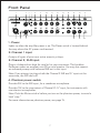
www.fishman.com
USER GUIDE
LOUDBOX PERFORMER
Read Me!
Take a few minutes to read through this manual before you power up the
Loudbox Performer. To jump in immediately, start with the Important Safety
Instructions and the Getting Started sections. While this information will get
you on your way, it is not considered a substitute for reading the entire manual.
Save Your Packing Materials
The box and packing materials for the Loudbox Performer were specially
designed to protect the amplifier during shipping. Save all this stuff in case
you need to re-ship the Loudbox Performer.
Table of Contents
Safety Warnings
3
Welcome
5
Getting started
6
Front Panel
7–9
Rear Panel
10–12
Tone Tips
12–13
About Acoustic Feedback
14
Phantom Power FAQs
15
Stereo Blending
16
Block Diagram
17
Specifications
18–19
Wherever this symbol appears, it alerts you to the presence of
uninsulated dangerous voltage inside the enclosure that may be
sufficient to constitute a risk of shock.
Whenever this symbol appears, it alerts you to the presence of
important operating and maintenance (servicing) instructions in the
user’s manual for this amplifier.
2
CAUTION
Risk of electric shock.
Do not open.
No user serviceable parts inside.
Refer servicing to qualified personnel.
Do not expose to rain or moisture.
Important Safety Instructions
To ensure your personal safety and the safety of others, operate this apparatus
only after reading these instructions and heeding the warnings listed below.
1. Read these instructions.
2. Keep these instructions.
3. Heed all warnings.
4. Follow all instructions.
5. Do not use this apparatus near water.
6. Clean only with a dry cloth.
7. Do not block the ventilation openings. Install in accordance with the
manufacturer’s instructions.
8. Do not install near any heat sources such as radiators, heat registers, stoves or
other apparatus (including amplifiers) that produce heat.
9. Do not defeat the safety purpose of the polarized or grounding-type plug. A
polarized plug has two blades with one wider than the other. A grounding-type
plug has two blades and a third grounding prong. The wide blade or the third
prong are provided for your safety. If the provided plug does not fit into your
outlet, consult an electrician for replacement of the obsolete outlet.
10. Protect the power cord from being walked on or pinched, particularly at the
plugs, convenience receptacles and the point where they exit from the apparatus.
11. Use only attachments/accessories specified by the manufacturer.
12. Use only with a cart, stand, tripod, bracket or table specified
by the manufacturer, or sold with the apparatus. When a cart is
used, use caution when moving the cart/apparatus combination
to avoid injury from tip-over.
13. Unplug this apparatus during lightning storms or when
unused for long periods of time.
3
14. Refer all servicing to qualified service personnel. Servicing is required
when the apparatus has been damaged in any way, such as a power-supply
cord or plug is damaged, liquid has been spilled or objects have fallen into
the apparatus, the apparatus has been exposed to rain or moisture, does not
operate normally, or has been dropped.
Do not expose the apparatus to dripping or splashing liquids and do not
place objects filled with liquids (such as a beverage container or a vase) on
the apparatus.
Disconnect device is AC inlet or power switch.
Warning: To reduce the risk of fire or electric shock, do not expose
this
apparatus to rain or moisture.
Hear This!
The Loudbox Performer amplifier is capable of cleanly reproducing the sound
of your instrument at very high volume levels. Prolonged repeated exposure to
high sound pressure levels (SPLs) without protection can cause permanent hearing loss. OSHA has set guidelines and specified permissible sound-exposure
limits for those who work in high SPL environments.
Permissible noise exposures
Duration per day,
hours
Sound level dBA
slow response
8
6
4
3
2
1½
1
½
¼ or less
90
92
95
97
100
102
105
110
115
To ensure against permanent hearing loss, wear hearing protection when you
perform with amplification.
4
Welcome . . .
. . . and thank you for choosing the Fishman Loudbox Performer! Our passion for
acoustic instruments inspired us to create this amp—it is our sincere wish that
the Loudbox Performer will inspire you as well!
With its unique tri-amplified design, the potent and portable, two-channel,
130 watt Loudbox Performer delivers more serious acoustic tone and volume
than any other amp in its class. The secret to the Loudbox Performer’s sound lies
in its three power amps and two-way speaker system. This powerful combination
results in higher sound pressure levels and cleaner acoustic tones, watt-for-watt,
than comparable acoustic amps.
You’ll find this lightweight and compact amp is as comfortable in your home
studio as it is onstage. It easily passes the “one-trip” test, for those times you
carry both your instrument and your amp to the car or into the club.
The two-channel Loudbox Performer brings together a wish list of the essential
features you’ve been looking for. The front panel includes inputs for acoustic
instruments, a microphone and a CD player or drum machine. Dual EQ sections include bass, midrange and treble controls for easy, effective tone shaping. Vanquishing troublesome acoustic feedback is simple with independent
anti-feedback filters and phase switches for each channel. We also include five
digital effects you can really use: two halls, two plates, and a smooth chorus. A
convenient mute switch keeps things quiet when you tune up or take a break.
The Loudbox Performer also features a headphone jack for silent jamming or
practicing.
On the rear panel, good things come in
threes with D.I.s for channels 1 & 2, plus a
third summed Mix-D.I. output (watch your
soundperson smile). For pedal-heads,
each channel has its own effects loop,
a tuner out (Ch. 1) and a ¼” jack for a
remote mute switch. With the Loudbox
Performer on the floor, the speaker’s tendegree tilt-back angle helps to project
your sound up to ear level.
So what are you waiting for? Grab your
guitar and your Loudbox Performer and
go out and make some music!
If you have questions or comments,
please contact us through the Service
and Support section of our website at
www.fishman.com.
5
Getting Started
Here are some basic setup tips to help get you going. To operate the Loudbox
Performer safely, please read the entire manual, especially the Important Safety
Instructions on page 3.
If your amplifier has an operating voltage of 120V, plug the provided AC line
cord into the back of the amplifier.
If your amplifier operates at 230V, you must supply your own detachable power
cord. The cord you supply must have an IEC-style 320 connector at one end and
a male AC plug appropriate for your area at the other.
1. Locate the Power switch (above the rear panel power cord terminal) and switch
it off (down position), then connect the power cord.
2. Plug the Loudbox Performer into an electrical outlet with the appropriate AC
voltage.
NOTE: Operate the amplifier only at the voltage indicated in
the check box on the rear panel. Do not defeat the ground
prong on the AC cable; the safe operation of this amplifier
depends on a proper ground connection.
3. Push in the Mute switch and turn on the Power switch.
4. Connect your instrument to the Channel 1 input with a shielded ¼” cable.
5. Play aggressively and raise Channel 1 Gain until Clip LED flashes, then back
off the Gain until no clipping occurs.
6. Set the controls as illustrated below.
7. Push the Mute switch (out) and slowly raise the Master Volume to the
desired level.
6
Front Panel
1
3
2
4
6 7
8
9
10
11
12
13
14
5
15
16
18
19
17
20
1. Power
Lights up when the amplifier power is on. The Power switch is located behind
the amp above the AC power cord terminal.
2. Channel 1 input
Accepts all types of passive or active acoustic pickups.
3. Channel 2, XLR input
Plug in a balanced mic here for vocal or for your instrument. The Loudbox
Performer makes an excellent mini-PA or vocal monitor. You may also connect
an outboard preamp with balanced XLR out to this input.
Note: If you attempt to plug in both the Channel 2 XLR and ¼” inputs at the
same time, the XLR shuts off.
4. Phantom power switch
Provides 24V to the XLR input, for a condenser microphone.
Provides 15V to the ring contact of Channel 2’s ¼” input, for instruments with
mini-electret microphones.
Note: Push the Mute switch in before you turn on the phantom power, to avoid a
loud “pop.”
For more information on phantom power, see page 15.
7
5. Channel 2, ¼ input (stereo)
Accepts all types of passive or active acoustic pickups. The Ring contact of this
stereo TRS input is tied to Channel 1. An instrument with two signal sources
(such as pickup and mini-mic) can be routed via stereo cable through this jack to
both Channels 1 and 2 (see page 16 for setup).
Note: Unplug Channel 1 input before you use Channel 2’s ¼” input for stereo
blending. If you use both ¼” inputs simultaneously, Channel 1 takes priority and
shuts off the Channel 2 Ring signal.
With this setup, your pickup and onboard mini-mic can be EQ’d and blended
separately. Wire the mini-mic to Ring and the pickup to Tip and follow the
manufacturer’s instructions. Turn on Phantom 15V power if your mini-mic
requires it. Stereo cables are available through your Fishman dealer.
Note: Items 6–14 are identical for both channels.
6. Clip LED
The Clip LED will light when the Gain level is too high and the signal becomes
distorted. If the light comes on when you play, lower the Gain until the distortion
goes away.
7. 10dB Pad
If you have a high output pickup and the Clip LED comes on at low Gain settings,
push this switch in to put your pickup into a more useable range.
8. Gain
Use the Gain knob to set the level of the signal. If the Clip LED flashes when you
play, lower the Gain until the flashing stops. If either channel is unused, set its
Gain to 7 o’clock (off).
9. Low
Boost here to add weight to the sound. In general, boost bass at low volumes
and flatten it out (or cut) at higher levels. With the dial set at 12 o’clock, the
control is effectively out of the circuit.
10. Mid
This control affects how well the instrument blends in or stands out in the mix. At
loud volumes a midrange cut will achieve a more natural sound. With the dial set
at 12 o’clock, the control is effectively out of the circuit.
11. High
Boost highs to add “air” to the sound of the instrument. With the knob set at
12 o’clock, the control is effectively out of the circuit.
8
12. Anti Feedback
If you encounter low-frequency feedback, sweep this control to isolate and
eliminate it. Many guitars will benefit with the Anti Feedback knob set at about
10 o’clock. The Anti Feedback filter is off at the 7 o’clock position. To read more
about acoustic feedback, see page 14.
13. Phase
Use the Phase switch in conjunction with the Anti Feedback filter to eliminate
acoustic feedback. To read more about acoustic feedback, see page 14.
14. FX Level
Controls the amount of digital effects in the channel. Generally set this above
the Master FX Level.
15. Digital FX (select)
These built-in effects have been specially
chosen and voiced for acoustic instruments.
16. Digital FX Level (master)
Set the overall level of the Digital FX with
this knob. In general set this lower than the
individual Channel 1 and 2 FX Levels.
Digital FX Programs
1. Hall 1
2. Hall 2
3. Chorus
4. Plate 1
5. Plate 2
17. Master Volume
Set the overall level of the Loudbox Performer with the Master Volume. In
general put the Master Volume as high as possible (2 o’clock to 5 o’clock) to
achieve the cleanest sound.
18. Headphone jack
When you plug in stereo headphones here, the speakers shut off. This output
monitors Channels 1 & 2 and the Aux input, so you can play along with
pre-recorded music through the headphones.
19. Aux Level
Use this to control the level of the device you plug into the Aux input. Note that
the Aux channel is independent of the Mute switch, so you can play pre-recorded music on your breaks. If the Aux channel is unused, set the Aux level to off.
20. Mute
The Mute switch shuts off the signals from Channels 1 and 2 to the speakers and
all the XLR outputs. The mute does not affect the Aux channel, the Tuner out or
the effects sends.
9
Rear Panel
1
2
3
4
5
6
7
8
9
1. Tweeter Level
Set the front panel controls flat and adjust the tweeter level to where it sounds
best to you.
2. Aux Input
Plug in a line level stereo audio source such as a CD or MP3 player in this input.
The ¼” stereo (TRS) Aux Input mixes the signals to mono when amplified, but
will retain the source’s stereo image through the headphones jack.
3. Mute Foot Switch
Plug a mono, on/off (latching type) foot switch into this jack for remote access
to the Mute. The Mute Foot Switch duplicates and overrides the front panel
Mute switch.
4. Tuner out
Plug in an electronic tuner here. This output receives only the Channel 1 signal
and is independent of the mute, so you can tune with the speakers and the XLR
outs muted. The Tuner out can also be used as pre-EQ unbalanced D.I. out for
Channel 1.
5. Mix D.I. (Post)
Plug in here when you wish to send signals from both Channel 1 and 2 to a
mixing console or a slave amplifier. This post-EQ output is always ground
isolated to prevent ground loop hum.
6. Channel 2 effects loop (serial)
Patch an external effect (delay, reverb, chorus) through these jacks. Use a
standard ¼” shielded instrument cable to connect the Channel 2 send to the
input of the effect. Connect the Channel 2 return jack to the output of the effect.
The Channel 2 loop is located post-EQ and is compatible with battery-operated
stompbox-style effects processors.
10
7. Channel 2 D.I. Out (Pre-EQ)
You’ll find that this true direct output produces an uncolored signal that is
exceptional for recording. Use this output when you want a flat D.I. signal to go
to the board. In this case you leave it to the soundperson or recording engineer
to dial up your tone and effects from the console. This pre-EQ output is always
ground isolated to prevent ground loop hum.
8. Channel 1 effects loop (serial)
Patch an external effect (delay, reverb, chorus) through these jacks. Use a
standard ¼” shielded instrument cable to connect the Channel 1 send to the
input of the effect. Connect the Channel 1 return jack to the output of the effect.
The Channel 1 loop is located post-EQ and is compatible with battery-operated
stompbox-style effects processors.
9. Channel 1 D.I. Out (Pre-EQ)
You’ll find that this true direct output produces an uncolored signal that is
exceptional for recording. Use this output when you want a flat D.I. signal to go
to the board. In this case you leave it to the soundperson or recording engineer
to dial up your tone and effects from the console. This pre-EQ output is always
ground isolated to prevent ground loop hum.
Power switch
Lower the master volume or engage the Mute switch before you turn on the
amp. Flip the power switch to the up position and it will light, indicating the
amp is on.
AC power
Operate the amplifier only at the voltage indicated in the check box on the
rear panel.
For 120V amplifiers purchased in the USA, Canada and Mexico, plug in the
supplied detachable AC power cable.
For 230V amplifiers purchased outside the USA and Canada, you will need
to supply your own detachable AC cable. This cable must have an IEC-style
320 connector at one end, and a male AC plug appropriate for your region
at the other.
Disconnect device is AC inlet or power switch.
11
Fuse holder
The fuse is located within the AC power
receptacle on the back of the amp. Access
the fuse compartment with a small slotted
screwdriver.
For 120V amplifiers purchased in the USA
and Canada, replace the fuse with: LittelFuse®
type 218002 or equivalent 5 x 20mm, 2A, 250V,
time-delay fuse.
For 230V amplifiers purchased outside the USA
and Canada, replace the fuse with: LittelFuse®
type 218001 or equivalent 5 x 20mm, 1A, 250V,
time-delay fuse.
Power
120V
230V
120V / 230 - 240V ~AC
50 / 60Hz - 500W Max
FUSE: 120V T2AL / 230V T1AL
Replace with same type fuse as indicated
Fuse Holder
Tone Tips
You can find a balanced tone with the Loudbox Performer when you hear how
tone changes as the volume rises.
Set up
For reference, start with the tone controls flat (straight-up, twelve o’clock). In this
position, there is no equalization applied to your sound. Begin at a very low
volume and work your way up. As you turn up, try adjusting the Loudbox
Performer’s tone controls as recommended below.
12
1. Low volume
At a low volume (just above conversation level) our ears are not very sensitive
to bass and treble, so give the Low and High controls a good boost. Try three
o’clock on the dial.
2. Medium volume
At intermediate levels, when you need to raise your voice to be heard over the
music, the human ear is quite sensitive to midrange. Cut the Mid control to
about ten o’clock or to your taste. At this level our perception of bass and treble
starts to catch up to the rest of the tonal spectrum, so you can back off the Low
and High controls slightly for good tonal balance.
3. High volume
At loud levels, when you must shout to be heard over the music, your ears (and
your audience) will benefit from a deep midrange cut. Set the Mid dial between
nine and seven o’clock. Our perception of bass and treble “flattens out” at high
volumes, so you won’t need much, if any, Low or High boost. Set the Low and
High knobs to between twelve and one o’clock. In many cases you can also
improve the tone at very high volume if you cut bass. Try setting the Low knob
between ten and eleven o’clock.
13
About Acoustic Feedback
Feedback usually occurs in the lowest
octave of your instrument, generally with
two notes about a half step apart. The
lower type of feedback (cavity resonance) starts when the sound pressure
coming out of the speakers excites the
resonant air chamber inside your instrument. We have found that it is effective
to tune out an instrument’s cavity resonance feedback with the Anti Feedback
(notch filter) in the Loudbox Performer.
For acoustic guitar this occurs at G# on
the low E-string, or at about 100Hz. Turn
the Anti Feedback knob to about 11
o’clock to dial out this resonance.
Note that the circuit can be effectively
defeated by moving the dial to the Off
(7 o’clock) position.
The higher range of feedback (top
resonance) usually starts about a half or
whole step above cavity resonance of
the instrument. Top resonance feedback
happens when the sound pressure
coming off the speakers excites the
resonant frequency of the soundboard
of your instrument. For acoustic guitar
this occurs at A and above on the low
E-string. Push the Phase switch in and
out until you find the position that
subdues top resonance feedback.
14
Anti
Feedback
Lower
Feedback Range
(E to G#)
OFF
Upper
Feedback Range
(A and above)
Phase
Phantom Power FAQs
Q: I have heard 24V phantom power can damage some audio devices. True?
A: Yes, phantom power can damage the following:
1. An unbalanced dynamic mic that has been modified for XLR.
2. A balanced line-level device that is not designed to accept phantom
power (eg, some effects processors). Contact the manufacturer to
confirm compatibility.
3. Some older balanced wireless receivers can be damaged by phantom
power. Consult the manufacturer of the wireless unit for compatibility.
4. An instrument preamp or stompbox with an unbalanced output that is
modified for XLR.
Important note: Turn off phantom power if you plug any of the above into the
XLR input.
Q: Which devices are safe with 24V phantom power?
A: All the following can be used safely with phantom power:
1. All balanced condenser microphones.
2. All balanced dynamic microphones.
3. Many new wireless units. Check with the manufacturer for compatibility.
4. A preamp / D.I. designed for phantom-power operation, such as the
Fishman Pro-EQ Platinum.
15
Stereo Blending
If your instrument has two
signal sources (typically minimic and pickup) and stereo
output, you may route these
signals into separate channels
of the amp and blend them
independently for your own
custom mixes.
Loudbox Performer
1) Plug in a stereo (TRS) instrument cable between your guitar
and the Channel 2, ¼” input.
STEREO CABLE
2) Pickup (Tip) is routed to Channel 2
and Mic (Ring) is routed to Channel 1.
3) Turn on phantom power if mini-mic requires it.
Mic (ring) feeds Channel 1
Turn on Phantom if
mini-mic requires it.
Pickup (tip)
Mic (ring)
Pickup (tip) feeds Channel 2
16
Gain
Low
Mid
High
Anti
Feedback
Phase
FX Level
Digital FX
Level
Master
Volume
I
INPUT
S
IN
R
RIN SI NA
INPUT
17
I PREA P
INPUT
U ER
¼” STEREO
AUX INPUT
INPUT
U ER
I PASS
TIP = LEFT
RING = RIGHT
I PASS
PA
20dB
PA
O
O
P ANTO PO ER
AIN
AUX
E E
AIN
I
I
IP
ETE TION
IP
ETE TION
TUNER
OUTPUT
I
I
NOT
X
SEN
IP E
X
SEN
DIGITAL FX
SELECT
NOT
IP E
RIGHT
LEFT
X
RETURN
CH. 2 DIGITAL
FX LEVEL
DIGITAL FX
OUTPUT LEVEL
CH. 1 DIGITAL
FX LEVEL
X
RETURN
P ASE
P ASE
POST
SI NA
UTE
UTE
POST
SI NA
ANNE
UTE
MASTER
VOLUME
ANNE
A AN E
I OUTPUT
UTE
A AN E
I OUTPUT
CHANNEL
MUTE
RING
MUTE
MUTE
CONTROL
MUTE
LIMITER
MUTE
FOOT SWITCH
JACK
POWER
AMPLIFIERS
MUTED WHEN CONTACT CLOSED.
FOOT SWITCH JACK OVERRIDES FRONT PANEL SWITCH.
TIP
SLEEVE
LIMITER
LIMITER
POST MIX
D.I. OUTPUT
CHANNEL
MUTE
25Hz
HI-PASS
TWEETER
LEVEL
(FRONT PANEL)
18dB
PAD
LOW
MID
HI
CROSSOVER
JACK INSERTED MUTES
INTERNAL SPEAKERS
TIP
HEADPHONE
OUTPUT
Block Diagram
Technical Specifications
Rated power:
Cumulative
130Wrms
Woofer Amp
80Wrms continuous
Midrange Amp
40Wrms continuous
Tweeter Amp
10Wrms continuous
All measurements @ nominal line 120V, 60Hz
Acoustic response:
SPL @ 1 Meter
Frequency Response
117dB SPL
80Hz – 20kHz ± 4dB
Power consumption:
200W max
Input impedance:
Ch. 1
Ch. 2, ¼”Jack (Tip)
Ch. 2, ¼”Jack (Ring)
Ch. 2, XLR Input
Aux Input (stereo)
10MOhm
10MOhm
10MOhm, 10kOhm with 15V phantom power
2.4kOhm Balanced
10kOhm
Nominal input level:
Ch. 1
Ch. 2, ¼” Jack (Tip)
Ch. 2, ¼” Jack (Ring)
Ch. 2, XLR Input
Aux Input (stereo)
-20dBV/-10dBV with 10dB pad
-20dBV/-10dBV with 10dB pad
-20dBV/-10dBV with 10dB pad
-40dBV/-30dBV with 10dB pad
-10dBV
Maximum recommended
Ch. 1
Ch. 2, ¼”Jack (Tip)
Ch. 2, ¼”Jack (Ring)
Ch. 2, XLR Input
Aux Input (stereo)
input level:
6dBV
6dBV
6dBV
-14dBV
6dBV
Phantom power (Ch. 2 only):
XLR Input
24Vdc/6.8kOhm DC source impedance per pin
¼” Jack (Ring)
15Vdc/10kOhm DC source impedance
Tone controls and Anti Feedback (Ch. 1 and Ch. 2):
Low
±10dB @ 100Hz (shelving)
Mid
±12dB @ 1.2kHz (resonant)
High
±12dB @ 10kHz (shelving)
Anti Feedback range
-14dB @ 20 – 400Hz (Hi-Q resonant notch)
We reserve the right to change any of the the specifications and information in
this manual without notice.
18
Digital effects:
Program 1
Program 2
Program 3
Program 4
Program 5
Headphone Jack
Output Impedance
Max Output Level
Nominal Output Level
Channel 1 & 2 D.I. Out
Output Impedance
Hall 1
Hall 2
Chorus
Plate 1
Plate 2
22 Ohm
18.5dBV (rms)
-10dBV
600Ohm balanced
Phantom power tolerant, ground isolated
Channel 1 & 2 Effects Sends:
Output Impedance
2.2kOhm
Output Voltage
+3dBV (1.4Vrms max)
-10dBV Nominal
Channel 1 & 2 Effects Returns:
Input Impedance
20k Ohm
Input Voltage
+3dBV (1.4Vrms max)
-10dBV Nominal
Sends and returns are compatible with battery operated effects processors
Mix D.I. out:
Output Impedance
Tuner out:
Output Impedance
600Ohm balanced
Phantom power tolerant, ground isolated
5kOhm
Speaker system:
Woofer
Midrange
Tweeter
6.5” paper cone
4.5” polypropylene cone
1” soft dome,
rare earth magnet, ferrofluid cooled
Tweeter Level
Up to 6dB cut
Crossover
600Hz, 4kHz (Tri-amplified with active crossover)
Woofer and midrange installed in separate isolated and damped compartments
Baffle Angle
Upright position 10 degrees
With kickstand 45 degrees
Physical:
Dimensions
Weight
19.5” x 16” x 11.5” (49.5cm x 40.5cm x 29cm)
35 lbs (16 kg)
19
www.fishman.com
Fishman and Fishman Transducers are trademarks or tradenames of Fishman Transducers Inc.
513-000-021 Rev E 2-09