1
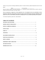
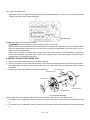
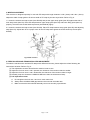
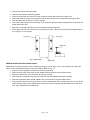
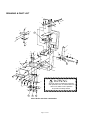
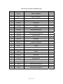
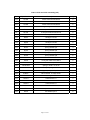
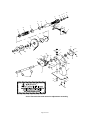
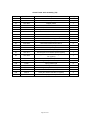
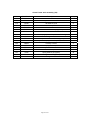
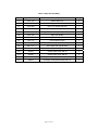
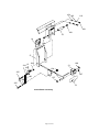
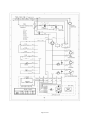
HIGH TABLE SEMI-AUTOMATIC
STRAPPING MACHINE
USER’S MANUAL
WARNING:
Read carefully and understand all ASSEMBLY AND OPERATION INSTRUCTIONS before operating.
Failure to follow the safety rules and other basic safety precautions may result in serious personal
injury.
Item# 22063
Thank you very much for choosing a Wel-Bilt™ product. For future reference, please complete the owner’s record
below:
Model: _______________
Purchase Date: _______________
Save the receipt, warranty and these instructions. It is important that you read the entire manual to become
familiar with this product before you begin using it.
This air compressor is designed for certain applications only. The distributor cannot be responsible for issues
arising from modification. We strongly recommend this item not be modified and/or used for any application other
than that for which it was designed. If you have any questions relative to a particular application, DO NOT use this
product until you have first contacted the distributor to determine if it can or should be performed on the product.
For technical questions, please call 1-800-222-5381.
TABLE OF CONTENTS
TECHNICAL SPECIFICATIONS…………………………………………………………..……………1
GENERAL SAFETY REGULATIONS……………………………………………..……………………1
SPECIFIC OPERATION WARNINGS……………………………………………………………..……2
INSTALLATION…………………………………………………..……………..…………………………2
START-UP ……………………………………………………..………………………….………………3
OPERATION………………………….…………..…………………………………………………………6
ADJUSTMENT INSTRUCTIONS …………………………………………………….…….……………6
ELECTRICAL DESCRIPTION ………………………….………………..………………………………8
PARTS CLEANING
……………………………………………………………..…………….....………8
MAINTENANCE AND LUBRICATION………………………………………………..…………………9
TROUBLESHOOTING……………………………………………………...……….……………………10
DRAWING & PART LIST………………………………………………………………..………………12
Page 1 of 38
TECHNICAL SPECIFICATIONS
Item
Description
Packing Speed
<3 second/cycle
Min Package
2 3/8in. (60mm)
Tension Force
17.6lbs.-110lbs. (8kgs-50kgs)
Width of PP Tape
0.24in.–0.6in. (6-15mm)
Thickness of PP Tape
0.02in.-0.033in. (0.5mm-0.85mm)
Power Voltage
AC110V
Power Frequency
60HZ Single phase
Power
<0.4kw
Machine Weight
<220lbs. (100KG)
Ambient Temperature
41°F-104 °F (5-40 °C)
Relatively Humidity
35-85%RH
Transportation/ Storage Temperature
-13° - +131°F (-25- +55°C)
GENERAL SAFETY REGULATIONS
1. Keep the work area clean and dry. Damp or wet work areas can result in injury.
2. Keep children away from work area. Do not allow children to handle this product.
3. Store idle equipment. When not in use, tools and equipment should be stored in a dry location to inhibit rust.
Always lock up tools and equipment, and keep out of reach of children.
4. Use the right tool for the job. Do not attempt to force small equipment to do the work of larger industrial
equipment. There are certain applications for which this equipment was designed. It will do the job better and more
safely at the capacity for which it was intended. Do not modify this equipment, and do not use this equipment for a
purpose for which it was not intended.
5. Check for damaged parts. Before using this product, carefully check that it will operate properly and perform its
intended function. Check for damaged parts and any other conditions that may affect the operation of this product.
Replace damaged or worn parts immediately.
6. Do not overreach. Keep proper footing and balance at all times to prevent tripping, falling, back injury, etc.
7. DO NOT use the equipment when tired or under the influence of drugs, alcohol, or medication. A moment of
inattention while operating this equipment may result in serious personal injury.
8. Industrial applications must follow OSHA requirements.
Page 1 of 38
SPECIFIC OPERATION WARNINGS
WARNING: Read and understand all instructions BEFORE operating.
WARNING: The warnings, cautions, and instructions discussed in this instruction manual cannot
cover all possible conditions or situations that could occur. It must be understood by the operator that
common sense and caution are factors that cannot be built into this product, but must be supplied by the operator.
1.
2.
3.
4.
5.
6.
7.
8.
9.
Before operating the machine, pleases fit over voltage and under voltage protection to the machine.
Wear eye or face, and hand protection. Do not wear loose clothing.
Keep hands or other parts of the body out of the strap chute area during operation.
The temperature of the heater plate is very high. Do not touch.
Do not insert strap while there is not a package on the operation table.
Do not replace any safety parts of different specifications.
Shut off all electric power after machine operation or servicing machine.
Do not use water or steam to clean the machine.
Do not remove the electric control box cover if not necessary. Only trained engineers are allowed to open the
electric box. Before opening, be sure to pull the power plug off.
10. Keep this operation manual at your strapping machine. Refer to it often.
INSTALLATION
One set of tools and spare parts is packed with each machine for use in making adjustments and for replacement
of parts as needed. Please compare your supplied tools with the following list:
SPECIFICATION
NAMES
QTY
EX102
FUSE 2A
1
EX103
FUSE 3A
1
EX115
FUSE 15A
1
EW001
MICRO-SWITCH, WITHOUT IDLER WHEEL
1
EW002
MICRO-SWITCH, WITH IDLER WHEEL
1
HL101122
LONG PULLED SPRINGΦ1.0*Φ10.8*22
1
HL121020
SHORT PULLED SPRING Φ1.2*Φ10*20
1
HL050565
GALVANOTHERMY SMALL SPRING Φ0.5*Φ5*6.5
1
GB25
HEXAGON SPANNER M2.5
1
GB30
HEXAGON SPANNER M3
1
GB40
HEXAGON SPANNER M4
1
GB50
HEXAGON SPANNER M5
1
GA04
CROSS LAW APPROVED 4
1
Installation of the machine requires that the machine be uncrated, placed in its proper position and secured in
place (see Fig 1 for reference). Remove the screw on the top cap of speed reducer for ventilation. Make sure the
power cord is plugged into the appropriate electrical outlet.
Page 2 of 38
Fig1. Installation Dimension
START-UP
1. INTRODUCTION TO THE CONTROL PANEL
The control panel is at the upper left corner of the machine front plate (see Fig.2).
(1)
(2)
(3)
(4)
3
4
5
2
1
6
Fig.2 Control Panel
(1) Power switch
Turn on the switch. Power switch lights up in red indicating all electrical circuits and the electric motor are
active. Then you can operate the machine.
Turn off the switch, cut down the power, then the machine stops.
(2) Manual retracting/reset button
The button has either green or yellow light to indicate the 2 status alternatively.
When its green light is on, press the button, the straps will be retracted and the light turns to yellow.
When its yellow light is on, press the button, the machine will be reset and the light changes to green.
(3) Manual feeding
When the machine is in the "reset" model (the Manual retracting/reset button’s green light is on), press the
button (3), the straps can be fed manually.
While the Manual retracting button (2) is functioning (its yellow light is on), press the Manual feeding button (3)
will stop retracting and start feeding straps.
Page 3 of 38
(4) Length adjustment knob
Rotating the knob can adjust the feeding length of the straps automatically, so that you can set up a standard
length of the strap to fit the same packages.
Fig.3 Switch W1
(5) W1: Motor Stop Time Adjustment Switch
WARNING: Before making any switch changes, power must be OFF.
This machine can automatically switch off after a while of inactivity and restart as the strap is inserted. Please
follow the steps below to adjust the time for the motor to switch off automatically. The switch (W1 in Fig 3 is
used to make this adjustment).
Time for the machine in inactivity will be longer before the motor switches off automatically by turning the
switch (W1) clockwise, while time will be shorter by turning the switch (W1) anticlockwise. The time can be
adjusted from 10 seconds to 60 seconds.
2. INSTALLATION OF THE STRAP COIL
1. Screw off the hand wheel and take off the plastic flange B.
2. Place a coil of strap on the plastic flange A with correct direction allowing the shaft to poke through the plastic
wrap. Make sure the straps wheel inner diameter clip in reel center claw. If the inner diameter is wrong, adjust
it as below.
reel center claw
3. Replace the plastic flange B and reinstall the hand wheel.
plastic flange B
hand wheel
plastic flange A
dispenser shaft
Fig. 3 Dispenser Assembly
Please follow instructions below to adjust the reel center claw for various inner coils. Refer to Fig. 4.
1. For 200mm inner coil diameter, position 2 holes on the reel center claw to #1 and #3 holes of the plastic flange
A.
2. For 230mm inner coil diameter, position 2 holes on the reel center claw to #2 and #4 holes of the plastic flange
A.
Page 4 of 38
3. For 280mm inner coil diameter, position 2 holes on the reel center claw to #3 and #5 holes of the plastic flange
A.
plastic flange A
reel center claw
1
2
3
4
5
Fig.4 Reel Hole Site
3. FEEDING STRAPS (as shown in fig. 5)
E
D
C
COIL
B
Fig.5 Feeding straps
1. Turn off the machine by press power switch (1) as shown in fig.2 and pull the cord plug off the electric outlet to
cut off the power supply.
2. Open the door on the left side (see fig.3), and put the loaded strap reel in the case with the right direction, so
that the reel should turn clockwise when the straps are pulled off. (refer to detailed Notes on how to assemble
the straps onto the reel as stated below)
3. Close the left side door and open the right side door, pull the PP straps end until about 1 meter (3 fee ) straps are
off the reel.
4. Put the end of the straps through ring (B) to transition wheel (C), and make it go out from the side face, then close
the right side door.
5. Plug the cord into the appropriate electrical outlet and press the Power switch on.
6. Press the Manual feeding button (3), the machine will run. In the way indicated by the arrows in fig. 2, let the end
of the straps go through the slot (D).Feed the straps manually, the machine will pull the straps in. Do not release
the button until the end of straps comes out from point E.
Page 5 of 38
OPERATION
Fig.6 Sample Operation
1.
2.
3.
4.
5.
Install coil A on dispenser (Refer to Section 2, “Installation of the Strap Coil” in START-UP).
Feed the strap (Refer to Section 3, “Feeding Straps” in START-UP).
Connect power plug F to power source (AC 110V, 60Hz).
Turn on the power switch G and run the machine for 5 seconds to warm up to the operating temperature.
Place package K on the table top, directly above the sealing head. Allow the package to contact the two
package stops.
6. Manually pull the strap L to encircle the package. Or press feed button L to gain enough for encircling package.
7. Insert strap end into slot M, then machine will work automatically. Keep your hands away of the strap and slot
M during strapping.
8. After strapping, take the package away.
NOTE: Some adjustments may be required to let the machine work well. Please refer to the below section
ADJUSTMENT INSTRUCTIONS to adjust accordingly.
ADJUSTMENT INSTRUCTIONS
1. TEMPERATURE ADJUSTMENT
Open the top cover of the machine and find the switch for temperature adjustment.
The temperature increases when turning the switch on the transformer clockwise (The larger the number pointed
is, the higher the temperature is). The adhesive affection will not be very good if the temperature too high or too
low, so adjust in small increments. Normally, switch it on 4-6.
NOTE: If the temperature is adjusted too high (above 6), the high temperature heating filament is easy to be burnt
out.
2. TENSION ADJUSTMENT
Find the switch for tension adjustment on the backside of the machine)
Adjust the screw cap (Fig. 6) on the backside of the machine. Tighten the tension by turning clockwise, while
loosen by anticlockwise. The change can also be seen from the pointer (Fig. 7).
Screw cap
Pointer
Fig.7 Pointer
Fig.6 Screw cap
Page 6 of 38
3. WIDTH ADJUSTMENT
This machine is designed specially for use with PP straps with length between 0.24in. (6mm) and 0.6in. (15mm).
Adjust the width of strap guide to fit various width of PP strap by the two ways below. Refer to Fig. 8.
1. Loosen the socket head cap screws (item #5& #6) and put the upper strap guide (item #3) against the side of
main body block (item #9). Place PP strap between upper strap guide (item #3) and lower strap guide (item #4)
properly. Screw the two socket head cap screws (item #5& #6) tightly.
2. Loosen the socket head cap screws (item #7& #8). Place PP strap between strap guide (item #2) and adjusting
strap (item #1). Adjust item #1 to a proper room for the PP strap then tighten the socket head cap screws (item
#7& #8).
Fig.8 Guide Location
4. FEED ROLLERS AND TENSION ROLLERS ADJUSTMENT
To make the machine work well with PP straps with different thickness, please adjust the rollers following the
instructions as below. Refer to Fig. 9.
(1) The adjustment must be done after the machine is set to zero.
(2) Adjust the four lock nuts 1 and 2 upward, the clearance of the tension rollers is smaller.
(3) Adjust the four lock nuts 1 and 2 downward, the clearance of the tension rollers is larger.
(4) Normally, keep the clearance 0.05MM-0.1MM more than the thickness of strap.
(5) It is important to note:
A. Do not tighten the lock nuts 1 and 2 too much each time.
B. Always leave 0.3MM-0.5MM gap between the nuts and the holder arm.
C. Make sure that the idler wheels assembly can move smoothly up and down.
Page 7 of 38
Fig. 9 roller assembly adjustment details
ELECTRICAL DESCRIPTION
A circuit diagram of the electrical description is illustrated in the DIAGRAM & PARTS LIST section. Below are
functions of each main switch on circuit. Refer to Fig. 10.
LS1: It’s at the left hand of board. The machine begins to pack when strap head hits the touch-contact switch
through inserting slot.
LS2: It is magnetic switch which positions between up and down rollers. LS2 will sent out signal twice if magnet
rotates one circuit.
LS3: Retract straps when this switch is open, while cool when off.
LS5: It is beside of LS3. The contact point will be pushed by cam of micro-switch when the machine is set to zero.
After one packing, the electromagnet will be activated, then the strap can be fed automatically.
Quick heater system: Quick heater system is upon the bottom plate. It can make the machine to get the suitable
temperature in 30 seconds.
LS1
LS2
LS5
LS3
Fig. 10
PARTS CLEANING
UPPER SLIDE
Always keep the upper slide well fitted with both guides, and keep it move smoothly. Thus it is important to keep
the upper slide clean. Do the cleaning following the instructions below. Refer to Fig. 11.
¾ Remove the pull springs on the swaying rocker.
Page 8 of 38
¾
¾
¾
¾
¾
¾
¾
¾
Take out the upper and lower slides.
Wipe the slot between slides and guides.
Insert the lower slide into upper one, then screw the upper slide to the slot of lower one.
Slide both slides to the lots of both guides, then fix the spring pin with ungula slot of the upper slide.
After the slides are set down, put on the springs.
Check if the upper slide moves smoothly. If not, keep the right guide stay and adjust the left guide till the
upper slide works well.
Add some oil or light lubrication to the slot between slides and guides.
If the upper slide can move smoothly, but cannot move back, check if the pull spring is flexible fatigue. If
so, change it or cut it shorter.
left guide
right guide
clearance
Fig. 11 upper slide
upper slide
MIDDLE KNIFE AND FRONT POINT KNIFE
Middle knife and front point knife must cooperate precisely to cut off strap. So it is very important to keep them
clean. Do the cleaning following the instructions below. Refer to Fig. 12.
¾ Remove the pull springs of middle knife and front point knife.
¾ Move back the upper slide, take out the middle knife first and then the front point knife.
¾ Wipe the middle knife, front point knife and grooves clearly.
¾ After cleaning, assemble the front point knife, and then the middle knife and the springs.
¾ Add some light lubrication around middle knife, front point knife and rear knife around.
¾ If the machine has been used for long time, and the middle knife and front point knife can not cut off the
strap smoothly, take out the middle knife, remove the screws of spring and assemble them to the other
side, then reassemble the middle knife.
Page 9 of 38
middle knife
rear point knife
adjustment
front point knife
Fig. 12
MAINTENANCE AND LUBRICATION
The machine requires periodic maintenance and lubrication. Do not keep the product in the wet and moist place in
order to prevent the danger of fine or electrical damage. Always keep it dry.
1. On a weekly basis, clean out the rubbish in the machine.
2. On a monthly basis, make the cleaning to the parts in PARTS CLEANING section.
3. On three-month basis, lubricate axis and bearings.
4. On two-year basis, make up the machine oil in gearbox.
5. Do not add oil to the parts below.
A. Feeding rollers and tension rollers
B. All belts and pulleys
C. Skid piece and around
D. All the gears
E. Electromagnetic clutch and clutch disc
6. Do not add too much oil once, or oil may go into micro-switches causing malfunction.
WARNING: Only trained or professional personnel can service the machine. Make sure the machine is cool
and the wire plug has been disconnected before servicing.
TROUBLESHOOTING
Trouble phenomena: Band is not inserted properly.
Cause
Troubleshooting
1. Blocked with a lot of foreign materials.
Remove any debris.
2. Clutch works abnormally.
Low voltage.
The clearance of clutch is too big.
3. Something wrong with PCB.
Replace PCB.
Trouble phenomena: Strap can not be fed automatically.
Cause
Troubleshooting
1. Length adjustment knob was turned to
zero.
Turn the knob in clockwise direction to lengthen the strap. Gradation is
about 40” (1m).
2. Feed the strap in wrong way.
Re-feed the strap according to the instructions in STRAPS FEEDING
section.
3. Blocked with many foreign materials.
Remove any debris.
4. Improper clearance between idler
wheels.
Adjust the clearance according to ADJUSTMENT INSTRUCTIONS
section ADJUSTMENT FOR IDLER WHEELS OF FEEDING/
Page 10 of 38
RETRACTING STRAP .
5. PP strap is too thin or too thick.
Use straps with a length from 0.24in. (6mm) to 0.6in. (15mm).
6. Electromagnet worked abnormally.
Check if the electromagnet contact point falls off or burns out.
Check if the electromagnet moved away or was blocked by crumbs.
Check PCB.
Trouble phenomena: Strap can not be cut off.
Cause
Troubleshooting
1. The bearing of middle knife is broken.
Replace the bearing.
2. The middle knife is dull.
Bring new cutting surface into play according to PARTS CLEANING
section MIDDLE KNIFE AND FRONT POINT KNIFE .
3. Tension is too large.
Adjust according to ADJUSTMENT INSTRUCTIONS section
TENSION ADJUSTMENT .
4. There is oil on belts and pulleys.
Remove it and wipe the oil, then reinstall.
5. Drive belt is loose.
Tighten the belt by taking down the belt seat or moving backward the
motor.
6. Strap is too thick or clearance of the
idler wheels is too large.
Adjust the clearance according to ADJUSTMENT INSTRUCTIONS
section ADJUSTMENT FOR IDLER WHEELS OF FEEDING/
RETRACTING STRAP .
7. LS2 is malfunctioned.
While retracting strap, the reset button doesn’t work, and the manual
feeding button works. That means the LS2 doesn’t work.
Page 11 of 38
Trouble phenomena: Strap can not be retracted.
Cause
Troubleshooting
1. Blocked with many foreign materials.
Remove any debris.
2. Improper adjustment damaged the rail
bearing.
Only trained or professional personnel can service the machine.
3. Improper clearance between idler
wheels.
Adjust the clearance according to ADJUSTMENT INSTRUCTIONS
section ADJUSTMENT FOR IDLER WHEELS OF FEEDING/
RETRACTING STRAP .
Trouble phenomena: Strap can not be completely sealed.
Cause
Troubleshooting
1. Improper temperature.
Adjust according to ADJUSTMENT INSTRUCTIONS
TEMPERATURE ADJUSTMENT .
Repair or replace the fan if the temperature is too high.
2. Unnormal voltage.
The rated voltage is 110V. The range for the power voltage is ±5-10%.
3. The spring on galvanothermy loses
efficacy.
Replace the spring.
4.The bearing of middle knife is broken.
Change the bearing.
5. Heat-resisting wire
installed or burned out.
Check if the nut is loose. If so, coat it with conductive adhesive and
tighten it.
Replace a new heat-resisting wire.
6. Tension is too large.
was
wrongly
section
Adjust according to ADJUSTMENT INSTRUCTIONS section
TENSION ADJUSTMENT .
Trouble phenomena: Strap is cut off when strapping is not strong.
Cause
Troubleshooting
1. Tension is too small.
Adjust according to ADJUSTMENT INSTRUCTIONS section TENSION
ADJUSTMENT .
2. LS3 fails.
The machine cannot detect position when retracting strap, so it can not stop.
3. PCB fails.
Replace PCB.
Page 12 of 38
DRAWING & PART LIST
101
123
117
134
13
15
12
111
16
125
14
4
117
118
102
29
129
124
136
116 128113117
116
30
112
131
109
132
135
32
103
17
104
118
19
114
130
118
105
108
22
120
115
119
108
33
115
106
34
5
33
21
18
118
103
120
20
11
107
28
27
24
23
118
103
26
128
134
120
107
126
All parts must be periodically inspected
and replaced if worn or broken.Failure to
do this can affect a tool's operation
and present a safety hazard.
127
133
128
25
133
130
3
2
1
Chat 1 Knife and slide combination
Page 13 of 38
Chat 1 Knife and slide combination (1/2)
NO.
Specification
Description
Qty
1
AS1-11
1#knife combination
1
2
AS1-12
2#knife combination
1
3
AS1-13
3#knife combination
1
4
AS1-14
lower slide combination
1
5
AS1-15
gripping device assembly
1
11
AS1-101
cutting head
1
12
AS1-102
right plate
1
13
AS1-103
left plate
1
14
AS1-104
upper slide
1
15
AS1-105
upper slide baffle plate
1
16
AS1-106
start up switch
1
17
AS1-107
start up switch contact plate
1
18
AS1-108
screw with hole
1
19
AS1-109
micro-switch contact plate screw
2
20
AS1-110
knife block
1
21
AS1-111
knife block platen
1
22
AS1-112
L-type knife adjustment
1
23
AS1-113
knife block spring frame
1
24
AS1-11
1#knife
1
25
AS1-115
knife neck
3
26
AS1-116
knife screw
3
27
AS1-12
2#knife
1
28
AS1-13
3#knife
1
29
AS1-119
lower slide
1
30
AS1-120
lower slide shrapnel
1
32
AS1-122
gripping device
1
33
AS1-123
gripping device bushing
2
34
AS1-124
gripping device screw
1
101
SY512
socket head screw M5*12
4
102
SY56
socket head screw M5*6
1
103
SY516
socket head screw M5*16
2
Page 14 of 38
Chat 1 Knife and slide assembly (2/2)
No.
Specification
Description
Qty
104
SY520
socket head screw M5*20
2
106
SY625
socket head screw M6*25
2
107
SY650
socket head screw M6*50
2
108
SJ68
tightening screw M6*8
2
109
SP416
cross pan head screw M4*16
1
111
SP316
cross pan head screw M3*16
2
112
ML03
hexagon nut M3
2
113
ML04
hexagon nut M4
1
114
ML05
hexagon nut M5
1
115
ML08
hexagon nut M8
2
116
DT03
spring washer φ3
2
117
DT04
spring washer φ4
4
118
DT05
spring washer φ5
6
119
DT08
spring washer φ8
1
120
DT06
spring washer φ6
5
123
SY416
socket head screw M4*16
1
124
SP48
cross pan head screw M4*8
2
125
DP410
flat washer φ4*10
2
126
HY231042
spring in knife 2.3*10*42
3
127
HL121020
short pull spring1.2*10*20
1
128
HL101122
long pull spring φ1.0*φ10.8*22
4
129
EW001
Micro-switch ,no idler wheel
1
130
ZC635
bearing 635ZZ
4
131
XG414
barrel bolt 4*14
1
132
XG520
barrel bolt 5*20
1
133
XG514
barrel bolt 5*14
3
134
XG318
barrel bolt 3*18
5
135
SP35
cross pan head screw M3*5
2
136
DP38
flat washer φ3*8
2
Page 15 of 38
1
125
3
104
122
11
101 102
103
112
24 118
113
122
145
133
23
144
135
142
12
143
123
106
127
126
28
136
101
120
110
120
101
102
21
108
114
106
139
124
132
132
17
127 14
128
121
115 108
129
2
108
131
114
18
130
121 20
29
16
131
15
131
19
140
124
22
114
107
102
101 27
108
121
105
119 141 25
LS-5 138
Chat 2 Cam and gearbox assembly
Page 16 of 38
LS-3
116
Chat2 Cam and gearbox assembly (1/2)
No.
Specification
Description
Qty
1
AS1-21
reducer combination
1
2
AS1-22
cam combination
1
3
AS1-23
motor fan combination
1
11
AS1-201
clutch strap wheel
1
12
AS1-202
aluminum reducer
1
14
AS1-204
cam burnish axes
1
15
AS1-205
1#knife cam
1
16
AS1-206
2#knife cam
1
17
AS1-207
3#knife cam
1
18
AS1-208
Heating grippinf device jaw
1
19
AS1-209
Gripping device jaw
1
20
AS1-210
Refeed jaw
1
21
AS1-211
Big bearing base
1
22
AS1-212
Small bearing base
1
23
AS1-213
motor strap wheel
1
24
AS1-214
motor fan
1
25
AS1-215
micro-switch base plate
1
27
AS1-217
micro-switch spacer
1
28
AS1-218
clutch iron washer
1
101
SP412
cross pan head screw M4*12
9
102
DT04
spring washer φ4
9
103
ML10H
hexagon nut M10 thickening
2
104
DT10
spring washer φ10
1
105
ML03
hexagon nut M3
2
106
SS625
socket head screw(with washer) M6*25
6
107
DP410
flat washer φ4*10
2
108
DT06
spring washer φ6
12
109
ML06
hexagon nut M6
8
110
SS620
socket head screw(with washer) M6*20
2
112
SJ610
tightening screw M6*10
2
113
SY512
socket head screw M5*12
2
Page 17 of 38
Chat2 Cam and gearbox assembly (2/2)
No.
Specification
Description
Qty
114
SY620
socket head screw M6*20
3
115
SY645
socket head screw M6*45
1
116
SP330
cross pan head screw M3*30
2
118
DP512
flat washer φ5*12
2
119
DT03
spring washer φ3
2
120
DP616
flat washer φ6*16*2
12
121
KS17
retainer S-7
4
122
ZC62012
bearing 6003ZZ
2
123
EA001
Motor 110/220V 60Hz
1
124
ZC6003
bearing 6003ZZ
2
125
DH12164
Pad ring 12*16*4
1
126
DW12172
steel washer φ12*17*0.2
1
127
JY5514
Double round key 5*5*14
1
128
JY5580
Double round key 5*5*80
1
129
JY5516
Double round key 5*5*16
2
130
DJ17296
glue washer φ17*29*6
1
131
DJ172910
glue washer φ17*29*10
3
132
DJ172912
glue washer φ17*29*12
2
133
DH12168
pad ring 12*16*8
1
135
OF16M
reducer oil plug
1
136
OF16
O type apron φ16
1
138
EW002
Micro-switch, with idler wheel
2
139
SL616
socket head screw M6*16
3
140
DJ17298
glue washer φ17*28*8
1
141
DP38
flat washer φ3*8
2
142
SZ38
cross pan head screw M3*8
1
143
EM006
06clutch loop
1
144
EM001
06clutch acetabula
1
145
EM000
06brake block
1
Page 18 of 38
14.1
117 130
15
1
126
128
130
126
123
128
130
123
128 132
123
101
11
130
12
112
126
17
125
123
126
16
13
18
17
112
30
103
31
103
103
109
101
111
108
101
119
112
32
29
109
33
27
2
109
106
126
123
126
114
127
137
105
128
127
116
23
128
130
125
123
24
124
131
100
124
22
123
121 122
129
131
123 124
130
20
21
28
135
14.2
120
111 112
110
Chat 3 Strap feeding/ retracting and tension assembly
Page 19 of 38
15
25
Chat 3 Strap feeding/ retracting and tension assembly (1/2)
No.
Specification
Description
Qty
1
AS1-31
up extension combination
1
2
AS1-32
down extension combination
1
11
AS1-301
up extension fore axle
1
12
AS1-302
down extension rear axle
1
13
AS1-303
up extension
1
14.1
AS1-304
Roll, 40mm
2
14.2
AS1-304A
Roll, 39.5mm
2
15
AS1-305
small glue gear
2
16
AS1-306
up extension thin iron gear
1
17
AS1-307
up extension fore and after
conduction band piece
2
18
AS1-308
up extension middle conduction
band piece
1
20
AS1-310
up-down extension coupling shaft
1
21
AS1-311
turbine pulley axis
1
22
AS1-312
down extension short axis
1
23
AS1-313
down extension long axis
1
24
AS1-314
down extension
1
25
AS1-315
big glue gear
1
27
AS1-317
down extension thick glue gear
1
28
AS1-318
wheel glue slide
1
29
AS1-319
up extension front and down
conduction band piece
1
30
AS1-320
up extension front and up
conduction band piece
1
31
AS1-321
up extension middle conduction
band piece
1
32
AS1-322
up extension after and down
conduction band piece
1
33
AS1-323
up extension after and up
conduction band piece
1
100
SP316
cross pan head screw M3*16
1
101
SP48
cross pan head screw M4*8
6
102
SC46
cross pan head screw M4*6
2
103
SC48
cross pan head screw M4*8
10
105
SY512
socket head screw M5*12
1
106
SJ58
tightening screw M5*8
2
Chat 3 Strap feeding/ retracting and tension assembly (2/2)
Page 20 of 38
No.
Specification
Description
Qty
108
DT06
spring washer φ6
4
109
SY620
socket head screw M6*20
4
110
ET002
magnetism armature spring switch
1
111
DT04
spring washer φ4
1
112
DP410
flat washer φ4*10
7
114
DT05
spring washer φ5
1
116
DP621
flat washer φ6*21*2
1
117
SJ68
set screw M6*8
1
119
ML04
hexagon nut M4
2
120
SP420
cross pan head screw M4*20
1
121
DT03
spring washer φ3
1
122
DP38
flat washer φ3*8
1
123
ZC6002
bearing 6002ZZ
8
124
DJ15225
glue washer φ15*22*5
3
125
DW152110
steel washer 15*21*10
4
126
DJ15224
glue washer φ15*22*4
6
127
JY5512
double round key 5*5*12
1
128
JY5516
double round key 5*5*16
5
129
JP5532
crue cut key 5*5*32
1
130
KS15
Retainer S-15
9
131
KS10
Retainer S-10
2
132
JY5514
double round key 5*5*14
1
135
EU01
alnico
1
137
JY5510
double round key 5*5*10
1
Page 21 of 38
125
116
102
111
15
14
13
123
131
12
131
35
120
12
16
18
20
17
121
122
118
104
123
106
20
127
113
104
19
121
111
123
104
123
121
104
30
105
29
27
31
28
126
112
112
103
111
112
111
102
Chat 4 Transmission and extension adjustment assembly
Page 22 of 38
32
Chat 4 Transmission and extension adjustment assembly
NO.
Specification
Description
QTY
12
AS1-402
spring plastic cover nut
2
13
AS1-403
elastic outposting cover nut
1
14
AS1-404
elastic outposting sleeve
1
15
AS1-405
Tension control roll
1
16
AS1-406
elastic outposting pointer
1
17
AS1-407
big tension strap wheel
1
18
AS1-408
tight bundle strap wheel with climb
1
19
AS1-409
small tight bundle strap wheel
2
20
AS1-410
repeating slide
2
27
AS1-417
transmission frame connect axis
1
28
AS1-418
Transmission frame polished axis
1
29
AS1-419
transmission frame aluminum base
1
30
AS1-420
transmission frame
1
31
AS1-421
dicolpate strap wheel
1
32
AS1-422
monocolpate strap wheel
1
35
AS1-425
glue bushing
1
102
SY616
Socket head screw M6*16
5
103
SL670A
hexagonal head screw M6*70
1
104
SJ610
set screw M6*10
4
105
SJ66
set screw M6*6
1
106
ML06
hexagon nut M6
5
111
DT06
spring washer φ6
7
112
DP616
Flat washer φ6*16*2
6
113
DP613
flat washer φ6*13
1
118
KR32
Ouch(hole used) R-32
1
120
HY453952
elastic spring φ4.5*φ39*52
1
121
FV19K
strapK-19
2
122
FV30M
strapM-30
1
123
ZC6002
bearing 6002ZZ
4
125
ZC60000
bearing 6000ZZ
1
126
KS15
ouch(axis) S-15
2
127
202A122105
flat washer 12*21*0.5
2
131
SY58
socket head screw M5*8
2
132
DT05
spring washer φ5
2
Page 23 of 38
115
105
105
106
27
29
26
5
30
28
110
138
111
137
110
111
110
111
120
121
110
112
119
107 109
111
110
111
134
103
139
15
108
16
21
126
124
17
134
130
129
107
23
119
114
14
109 119
131
107 109 119
122
113
2
SEE FIGURE 9-8
107
ITEM 16
110
109
12
13
1
111
108
111
107
3
21
110
106
125
127
102
124
104
111
110
105
125
11
130
123
117
136
18
106
116
21
133
116
117
22
101
132
138
106
116
Chat 5 Galvanothermy and straps feeding tension assembly
Page 24 of 38
106
Chat 5 Galvanothermy and straps feeding tension assembly (1/2)
NO.
Specification
Description
Qty
1
AS1-51
galvanothermy sway rocker assemble
1
2
AS1-52
quick-heater sheet steel combination
1
3
AS1-53
rail combination
1
5
AS1-55
adjustable plastic conduction band groove
combination
1
11
AS1-501
galvanothermy side iron
1
12
AS1-502
galvanothermy sway rocker
1
13
AS1-503
galvanothermy sway rocker screw
1
14
AS1-504
galvanothermy white iron frame
1
15
AS1-505
quick-heater sheet steel
1
16
AS1-506
strong or not nut
1
17
AS1-507
rail
1
18
AS1-508
bullet combination
1
21
AS1-511
rail spring glue sleeve
4
22
AS1-512
electromagnet semi-automatic angle iron
1
23
AS1-513
rail screw
1
26
AS1-516
adjustable conduction band groove main body
glued
1
27
AS1-517
adjustable conduction band groove adjust block
glued
1
28
AS1-518
adjustable conduction band groove stator
1
29
AS1-519
adjustable insert strap slot up piece
1
30
AS1-520
adjustable insert strap slot down piece
1
101
SL690A
hexagon nut M6*90
1
102
SL6105A
hexagon nut M6*105
1
103
SY650
socket head screw M6*50
1
104
SP416
cross pan head M4*16
1
105
SY512
socket head screw M5*12
5
106
DT05
spring washer 5
9
107
ML04S
stainless hex nut M4
7
108
ML05
hexagon nut M5
2
Page 25 of 38
Chat 5 Galvanothermy and straps feeding tension assembly (2/2)
No.
Specification
Description
Qty
109
DT04S
spring washer φ4,stainless
6
110
ML06
hexagon nut M6
13
111
DT06
spring washer φ6
11
112
ML08
hexagon nut M8
1
113
DT08
spring washer φ8
1
114
SP416
cross pan head screw M4*16
1
115
SY425
socket head screw M4*25
2
116
SL512
hexagon screw M5*12
6
117
DP512
flat washer φ5*12
2
118
DP613
flat washer φ6*13
2
119
DG4103
copper washerφ4X10X0.3
4
120
DP616
flat washer φ6*16*2
1
121
DP621
flat washer φ6*21*2
1
122
HL050565
galvanothermy small spring 0.5*0.5*6.5
1
123
HL101122
long-pulled spring φ1.0*φ10.8*22
1
124
HY081251
strong or not compressed spring 0.8*12*51
2
125
ZC635
bearing 635ZZ
2
126
HY402439
rail spring φ4*φ24*39
1
127
KE12
ouch(axis used) E-12
1
129
HL161026
electromagnet spring φ1.6*φ10*26
1
130
XG440
bolt 4*40
2
131
XG520
bolt 5*20
1
132
ES001
electromagnet 24VDC
1
133
OF16
O-model leather ring φ16
1
134
SL410S
stainless hexagon screw M4*10
4
136
XG414
bolt 4*14
1
137
SY616
socket head screw M6*16
4
138
DP512
flat washer φ5*12
8
139
DP410
flat washer 4*10
1
Page 26 of 38
114
OPTION
OPTION
109
123
15
104
116
16
115
102
117
107
102
16
22
19
103
21
111
23
104
121
23
27
122
28
127
129
120
124
20
109
12
18
118
113
110
11
112
125
14
17
1
29
101
126
125
126
25
24
26
Chat 6 Frame work assembly
Page 27 of 38
104
Chat 6 Frame work assembly (1/2)
No.
Specification
Description
Qty
11
AS1-1101
AS-11case
1
14
CD50
magnet
4
15
AS1-605
stopper plastic
1
16
AS1-1106
AS-11,13 stainless cover
1
17
LA75
plateau versatile-truckle
2
17
LB75
plateau brake versatile-truckle
2
18
AS1-608
door holder plastic
2
19
AS1-609
module motherboard
1
20
AS1-601
door used of conduction band groove
1
21
AS1-611
circular arc support
1
22
AS1-612
lift cover support cyrto-set
1
23
SY613RA
semi-socket head screw M6*13
2
24
AS1-614
lead belt pulley
1
25
AS1-615
lead belt pulley axis
1
26
AS1-624
AS-11,12 lead-belt pulley frame
1
27
AS1-617
de-energize micro-switch spacer (option)
1
28
AS1-618
de-energize micro-switch de-energize stainless
iron (option)
1
29
AS1-1102
AS-11,13front plate
1
101
SS612
hexagon nut(with washer) M6*12
18
102
DT06
spring washer φ6
8
104
ML06
hexagon nut M6
7
107
SS620
hexagon nut (with washer) M6*20
6
108
DP410
flat washer φ4*10
2
109
SP412
cross pan head screw M4*12 (option)
4
110
DT03
spring washer φ3
8
Page 28 of 38
Chat 6 Frame work assembly (2/2)
No.
Specification
Description
Qty
111
XG520
bolt 5*20
1
112
SP310
cross pan head screw M3*10
8
113
DP38
flat washer φ3*8
8
114
DP616
flat washer φ6*16*2
10
115
SY616R
semi-socket head screw M6*16
1
116
DC04
external-tooth washer φ4 (option)
2
117
SY612
socket head screw M6*12
2
power line's plug optioned as per manufacturing cell
1
118
120
ML04
hexagon nut M4
2
121
SP516
cross pan head screw M5*30 (option)
2
122
HY078021
compression spring to break φ0.7*φ8.2*20.5
2
123
MD06
butterfly nut M6
2
124
DT04
spring washer φ4
2
125
SP516
cross pan head screw M5*16
8
126
DP512
flat washer φ5*12
8
127
DT05
spring washer φ5 (option)
10
129
ML05
hexagon nut M5 (option)
8
130
ML03
hexagon nut M3
8
Page 29 of 38
104
101
11
21
13
100
16
14
11
102
17
19
103
20
104
24
Chat 7 Tape reel assembly
Page 30 of 38
23
Chat 7 Tape reel assembly
No.
Specification
Description
Qty
11
AS1-700
plastic tape reel
2
13
AS1-703
tape reel claw
3
14
AS1-809
AS-11,12,13tape reel axis
1
16
AS1-706
tape reel washer
1
17
AS1-707
big round head tape reel pin-axis φ8
1
19
AS1-709
tape reel handle
1
20
AS1-710
nylon bracket (left)
1
21
AS1-711
nylon bracket (right)
1
23
AS1-1110
AS-11tape reel left
1
24
AS1-1111
AS-11tape reel right bracket
1
100
KH25
ouch (axis used) S-25
1
101
SY612
socket head screw M6*12
4
102
SY620
socket head screw M6*20
6
103
XR08
galvanization M R model pin08
1
104
SS612
hexagon screw(with washer) M6*12
4
Page 31 of 38
104 102
110
109
108
16
14
108
17
15
104
104
102
13
108
104
105
106
107
11
107
102 104
105
12
Chat 8 Brake assembly
Page 32 of 38
Chat 8 Brake assembly
No.
Specification
Description
Qty
11
AS1-801
brake pole pulley axis
1
12
AS1-802
brake pulley
1
13
AS1-803
brake pole pulley frame
1
14
AS1-814
brake rubber-block
1
15
AS1-815
spring seat
1
16
AS1-816
brake pole axis
1
17
AS1-817
AS-11,12brake pole
1
18
AS1-811
AS-11,12brake frame
1
102
DT06
spring washer φ6
4
104
ML06
hexagon nut M6
6
105
SL620
hexagon screw M6*20
2
106
HL121347
brake spring φ1.2*φ13*47
1
107
KE05
ouch (axis used) E-5
2
108
KS10
ouch(axis used ) S-10
3
109
SS620
hexagon screw(with washer) M6*20
2
110
DP616
flat washer φ6*16*2
2
Page 33 of 38
All parts must be periodically inspected
and replaced if worn or broken.Failure to
do this can affect a tool's operation
and present a safety hazard.
126
130
134
115
106
15
12
115
124
106
107
13
option
139 138
14
132
134
136
107
1
127
100
19
128
102
101
106
125
106
112
107
17
16
121
122
131
134
21
119
See figure 6-1,item19
140
129
121
127
117
118
Chat 9 Electrical system
Page 34 of 38
121
127
Chat 9 Electrical system
No.
Specification
Description
Qty
1
AS1-56
fan combination
1
12
AS1-902
de-energize switch (option)
1-3
13
AS1-903
fan bracket
1
14
AS1-904
heat proof cover
1
15
AS1-905
heat proof seat
1
16
AS1-906
heat-proof line
2
17
AS1-907
white glue sheath
2
19
AS1-909
galvanothermy transformer cover
1
100
SE416
big flat head self-tapping screw M4*16
3
101
SP416
cross pan head screw M4*16
4
102
SZ38
cross pan head self-tapping screw M3*8
2
106
DP410
flat washer φ4*10
12
107
ML04
hexagon nut M4
4
112
DT04
spring washer φ4
4
115
SP412
cross pan head screw M4*12
4
117
EN001
yellow knob (option)
1
118
EN002
green knob (option)
1
119
EK001
black without light springboard switch
1
121
EP001
potentiometer 500K (option)
1-2
122
UN001
knob (black)
1
124
EF001
micro-fan 24VDC
1
125
EY1101
galvanothermy transformer 110V (option)
1
125
EY2301
galvanothermy transformer 110V (option)
1
126
EL001
double loop de-energize switch (option)
1-3
127
UN002
knob (red) (option)
1-2
128
APC-10D1
PC plate combination ,APC-10D1,110V (option)
1
128
APC-10D
Pc plate combination,APC-10D,220V (option)
1
129
EK002
red with light springboard switch (option)
1
130
SP516
cross pan head screw M5*16 (option)
2
131
SP56
cross pan head screw M5*6
4
132
DT05
spring washer φ5 (option)
2
134
DP510
flat washer φ5*10 (option)
8
136
ML05
hexagon nut M5 (option)
2
138
SL610
hexagon nut M6*10
2
139
DP613
flat washer φ6*13
2
140
UC001
down -leed groove H35*W25mm
2
Page 35 of 38
Chat 10 Electrical-box assembly
Page 36 of 38
Chat 10 Electrical-box assembly
No.
Specification
Description
Qty
11
AS1-B01
AS-10,11,13 e-box
1
12
AS1-B02
AS-10,11,13e-box cover
1
13
DS3575
mat beads (plastic)φ3.5*φ7*5
4
17
APC-10B1
PC plate combination,APC-10B1
1
102
EY1122
control transformer 110V/22V (option)
1
102
EY2322
control transformer 230V/22V (option)
1
104
EX115
fuse 15A (option)
1
105
EX103
fuse 3A (option)
0-1
105
EX102
fuse 2A (option)
1-2
106
EX01
fuse seat
3
108
SY48
socket head screw M4*8
4
109
UE001
speedness cramp(white)
4
112
SC316
cross deep head screw M3*16
4
113
DT03
spring washerφ3
4
114
ML03
hexagon nut M3
8
115
APC-10S
Pc plate combination, APC-10S
1
116
EP001
potentiometer 500K
1
122
UN002
knob (red)
1
124
SP412
cross pan head screw M4*12
2
125
DP410
flat washer φ4*10
6
126
DT04
spring washer φ4
6
127
ML04
hexagon nut M4
2
128
ML05
hexagon nut M5 (option)
4
129
DT05
spring washer φ5 (option)
4
130
DP512
flat washer φ5*12 (option)
4
For replacement parts and technical questions, please call 1-800-222-5381.
Page 37 of 38
Page 38 of 38
WARRANTY
1-year limited warranty
Distributed by:
Northern Tool + Equipment Co., Inc.
Burnsville, Minnesota 55306-6936
NorthernTool.com
Made in China
Page 39 of 38