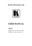
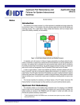
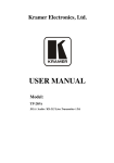
1
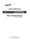
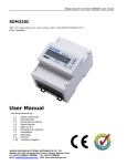
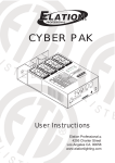
Technical Specifications:
DMX-16SW:
Power Input(DMX-16SW)..........................................................DC 9V, 200 mA min.
DMX In..........................................................................................3-pin XLR male
DMX Output................................................................................3-pin XLR female
Dimensions....................................................................................482x82x44mm
Weight........................................................................................................2.3kg
Accessories............................................................................An external Adaptor
DP-415:
Power Input (DP-415)........................................................................AC120V~60Hz, 15A Max.
DMX Output....................................................................................................3-pin XLR female
DMX Input..........................................................................................................3-pin XLR male
Fuses (Internal)................................................................................6A-250V 5x20mm (x 4pcs)
DMX-16SW SYS
Dimensions..........................................................................................................180 x177 x 64
Weight...............................................................................................................................1.4kg
*Special Note:
Improvements and changes in specifications and design to this manual and the unit
may be made at any time without any prior written notice.
DMX-16SW
DMX Switch Controller
DP-415
4 Channel DMX dimmer/switch pack
Elation Professional
4295 Charter Street
Los Angeles CA. 90058
www.elationlighting.com
P/N:24-004-2352-00
Rev1.0
-10-
USER MANUAL
Contents
Dip switches 1-9 are in place so a DMX address can be assigned to the pack. Dip switch 10
functions as a mode switch that allows you to select how you want the pack to operate. When
set to On, the pack will operate in "Switch" mode. When set to Off, the pack will operate in
"Dimmer" mode.
About the DMX-16SW SYS
Introduction...............................................................1
Unpacking.................................................................1
Customer Support.....................................................1
Caution......................................................................1
Warning.....................................................................2
Connection & Setup................................................3,4
DMX-16SW SYS Controller(DMX-16SW)
DMX-16SW features..................................................5
Controls & Functions..................................................5
Operation Guide.........................................................6
As the above illustration shows, each dip switch represents a DMX value. The top row of
numbers is the dip switch number and the bottom row is the value for each dip switch. Simply
flip the desired dip switch or switches to the ON position for which the binary values add up to
your desired address. For example, if your trying to get to channel 17 you would flip dip
switches 1 & 5 ON. See below for more help.
Additional examples:
DMX-16SW SYS Dimmer(DP-415)
Features.....................................................................6
Controls & Functions...............................................7,8
DMX Addressing......................................................8,9
Technical Specifications.........................................10
The DMX indicator will flash when DMX signal is present.
"Switch" / "Dimmer" mode selection:
Dip-switch 10 is the Mode selector switch. When set to "ON", the pack will be in switch mode.
When set to "OFF" the pack is in linear dimming mode.
In "Switch" mode, the channel output will have a switch point at value 128. This means
when relevant channel is below value 128, there will be no output for that channel. When
the value is at 128 or above, the output will be ON at 100% for the relevant channel.
In "Dimmer" mode, the intensity for each channel could be adjusted from 0 to 100% in real
time.
-9-
About the DMX-16SW SYS
Controls & Functions
Introduction:
Rear panel view
Thank you for your purchasing of the Elation Professional DMX-16SW SYS. To optimize the
performance of this product, please read these operating instructions carefully to familiarize
yourself with the basic operation of this system. The Elation Professional DMX-16SW SYS
is simple to use. All system components have been tested at the factory before being
shipped to you. Please simply connect cables between your DP-415 and DMX-16SW, then
you're ready to go!
Unpacking:
The DMX-16SW SYS has been thoroughly tested and shipped in perfect working condition.
Please take a few minutes to carefully inspect the system carton for damage that may have
occurred during shipping. If the carton appears to be damaged, carefully inspect each
system component for damage, in the case that damage is found, please contact our
customer support center, listed below, for further instructions. The Elation Professional DMX16SW SYS carton should includes the following:
1 DP-415
1 DMX-16SW
2 XLR DMX cable
1 External Adaptor
1 User's Manual
6. Power input:
Plug into an AC 120V~60Hz outlet.
7. Power Switch:
This switch turns the unit ON and OFF.
Customer Support:
8. DMX Input:
This 3-pin male XLR connector is the input and should be connected to a DMX controller or
the previous DMX device in line.
9. DMX Output:
This 3-pin female XLR connector is the output and should be connected to the next DMX
device in line.
Every effort has been made to design dependable and reliable products. New products are
constantly being designed to meet the needs of the entertainment lighting industry. Your
comments regarding our products and services are welcome. Elation Professional will
provide set up help and to answer any question should you encounter problems during you
set up or initial operation. You may also visit us on the web at www. elationlighting.com for
any comments or suggestions. And please send us an e-mail to info@ elation lighting.com
and let us know how to improve to better serve you. It is both a privilege and a pleasure
serving you.
Service Hours are Monday through Friday 8:00 a.m. To 5:00 p.m. Pacific Standard Time.
Voice:(800) 322-6337
Fax:(323) 582-2610
E-mail:[email protected]
DMX Addressing
Caution!
There are no user serviceable parts inside this unit. Do not attempt any repairs yourself, doing
so will void your manufactures warranty. In the unlikely event your unit may require service,
please contact your nearest Elation Professional dealer.
Do not discard this carton in the trash, please recycle when ever possible.
Upon unpacking, carefully inspect your unit for any damage that any have occurred during
shipping. If damage may have occurred, do not plug the unit in, please contact your dealer
as soon as possible.
-8-
-1-
Controls & Functions
WARNINGS:
Front panel view
-Be sure to use a proper ground connection for all DP-415's.
-Do not remove or break off the ground prong from the electrical cord. The ground is used to
reduce the risk of electrical shock for fire.
-Do not allow for any liquids to spill into or onto your unit.
-Be sure that the local power outlet match that of the required voltage for your unit.
-Do not attempt to operate this unit if the power supply cord has been frayed or broken. Be
sure to route your power supply cord out of the way of foot traffic.
-Disconnect from main power before making any type of data connections.
-Do not remove the top cover under any condition. There are not user serviceable parts inside.
-Disconnect the unit's main power when left unused for long periods of time.
-Never plug this unit into a dimmer pack.
-Always be sure to mount this unit in an area that will allow proper ventilation. Allow about
6''(15mm) between this device and any surrounding walls or objects.
-Do not attempt to operate this unit , if it becomes damaged in any way.
-Never operate this unit when its cover is removed.
-To reduce the risk of electrical shock or fire, do not expose this unit rain or moisture.
1. Dual Edison Output sockets:
There are four dual Edison output sockets. Each socket is labeled with its relevant channel
number.Each channel is rated at 5A. Up to 15A can be ON at a time.
2. Channel output LEDs (1~4):
These four LED's indicate corresponding channel intensity.
3. Power indicator:
This LED should be lit when the pack is powered ON.
4. Dip-switches:
Dip switches 1-9 should be used to set the packs DMX address. Dip switch 10 should be used
to set the packs operation mode. When set to On, the operates in "Switch" mode. When set to
Off, the pack operates in "Dimmer" mode.
5. DMX indicator:
This LED flashes when DMX signal is present.
-2-
-7-
Operation Guide
Connection & Setup
Power Supply:
1. The dip switches1-9 are used to select the DMX start address, which are
corresponding to the 16 channels.
2. Those 16 switches can shift between ON and OFF, which can be indicated by the
corresponding LEDs. When a LED is on, it indicates the corresponding switch is in
ON mode (the corresponding DMX value is255); when a LED is off , it indicates the
corresponding switch is in OFF mode (the corresponding DMX value is 0).
3. When the device is in HTP mode, that is in link condition, it output the bigger value
between the inputted DMX 512 signal and the 16 channels value which corresponds
to the device's address.
Before plugging your unit in, be sure the source voltage in your area matches the required
voltage for the DMX-16SW SYS. Be sure to plug your power supply into a wall outlet with
matching power before attempting to operate. And complete the system connection by using
3-pin Power/data extension cables.
Data Cable (DMX Cable) Requirements:
Your controller and packs require a standard 3-pin XLR connector for
DMX data input and DMX data output (Figure 1). If you are making your
own cables be sure to use standard two conductor shielded cable (This
cable may be purchased at almost all pro sound and lighting stores). Your
cables should be made with a male and female XLR connector on either
end of the cable. Also remember that DMX cable must be daisy chained
and can not be "Y"ed or split.
Figure 1
Notice: Do not use the ground lug on the XLR connector. Do not connect the cable's shield
conductor to the ground lug or allow the shield conductor to come in contact with the XLR's
outer casing. Grounding the shield could cause a short circuit and erratic behavior.
DMX-16SW SYS Dimmer Pack(DP-415 )
Notice: Be sure to follow figures two and three when making your own cables.
COMMON
The DP-415 is a hybrid, 4 channel pack designed to both dim and switch. Dip switch number
10 on the pack functions as the mode switch. When it's set to On, the pack will operate in
"Switch"mode. When it's set to Off, the pack will operate in "Dimmer" mode. Whenever using
these packs to control Par Cans or any other type of conventional effect (fixture with no
transformer), dip switch 10 should be left OFF so to function in "Dimmer" mode. Each of the
packs four channels can hold a load of up to 5 amps. This is roughly equal to 600 watts. It is
very important to distribute the load evenly so to not blow a channel fuse. Each channel is
internally protected with a 6amp, 250V midget fuse. Each channel also features dual Edison
sockets so multiple lights can be plugged directly into the pack without having to use a tri-tap
DMX512 OUT
CONTROLLER
CONNECTOR
3 PIN XLR
XLR Male Socket
1 Ground
DMX+
1
3
DMX-
2 Cold
2
DMX512 IN
CONTROLLER
CONNECTOR
3 PIN XLR
Figure 2
XLR Pin Configuration
XLR Female Socket
2 Cold
1
3
2
Pin 1 = Ground
1 Ground
Pin 2 = Data Compliment (negative)
3 Hot
3 Hot
Figure 3
Pin 3 = Data True (positive)
Or plug bar.
Special Note: Line Termination.
Features:
- Compact 4 channel DMX dimmer/switch pack
- USITT DMX512 (1990) multiplexed digital control via 3-pin XLR connector
- Dual 15A Edison plugs per channel
- On/Off power switch
- 3-pin XLR In/Out
- 10 position dip switch setting
- Hanging bracket to hang on truss or rig to clamp
- LED power "ON" indicator
- Channel intensity LED indicators
- 5 Amps per channel, 15 Amps maximum ON at a time
When longer runs of cable are used, you may need to use a terminator on the last unit to
avoid erratic behavior.A terminator is a 120 ohm 1/4 watt resistor which is connected between
pins 2 and 3 of a male XLR connector (DATA + and DATA -). This unit is inserted in the female
XLR connector of the last unit in your daisy chain to terminate the line.Using a cable terminator
will decrease the possibilities of erratic behavior.
1
Figure 4
3
2
Termination reduces signal errors and avoids signal transmission problems
and interference. It is always advisable to connect a DMX terminal, (Resistance
120 Ohm 1/4 W) between PIN 2 (DMX-) and PIN 3 (DMX +) of the last fixture.
DMX Signal Cable. 120 ohm impedance DMX signal cable MUST be used for signal
connection.
-6-
-3-
DMX-16SW SYS Controller(DMX-16SW)
5-Pin XLR DMX Connectors
Some manufactures use 5-pin XLR connectors for DATA transmission in place of 3-pin. 5pin XLR fixtures may be implemented in a 3-pin XLR DMX line. When inserting standard 5pin XLR connectors in to a 3-pin line a cable adaptor must be used, these adaptors are
readily available at most electric stores. The chart below details a proper cable conversion.
3-Pin XLR to 5-Pin XLR Conversion
Conductor
3-Pin XLR Female(Out)
5-pin XLR Male(In)
Ground/Shield
Pin 1
Pin 1
Data Compliment(-signal)
Pin 2
Pin 2
Data True(+signal)
Pin 3
Pin 3
Not Used
Pin 4 - Do Not Used
Not Used
Pin 5 - Do Not Used
DMX-16SW features include:
-USITT DMX512(1990) multiplexed digital control, via 3 pin XLR connector
-16 switches which can be switched between on and off
-Power Requirement: DC9V 200mA Min
-Dimensions: 482x82x44mm
-Weight: 2.3kg
-Power Failure Memory
-10 position dip switch setting
-Accessories: An external Adaptor (Included)
Controls & Functions:
Front View:
2
1
1 Channel Switches:
2 Channel LEDs:
Control the output of the DMX 512 signal respectively.
Indicate the corresponding channel switch's state, ON
or OFF.
Rear View:
2
4
1
2
4
8
16
32
64
128
256
Serial Number:
Made in PRC
DMX Start Address
1
1
2
3
4
5
-4-
Dip Switches:
DMX Output Socket:
DMX Input Socket:
Power Supply Port:
Power Switch:
DMX OUT
DMX IN
3
DC INPUT:
9VDC,
200mA Min
POWER
5
Select the initial channel setting mode.
Used to connect to DMX input socket of next unit.
Used to connect DMX signals.
Used to connect the Adaptor.
When in power, put the power on or off.
-5-