1
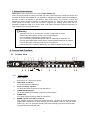
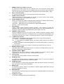
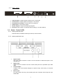
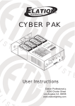
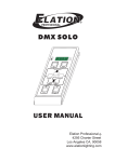
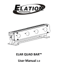
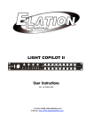
LIGHT COPILOT III
User Instructions
(Rev 1.0
24-004-1264)
E-mail: info@ elationlighting.com
Internet: http://www.elationlighting.com
1 General Introduction
Thank you for your purchase of our product LIGHT COPILOT II.
This is a high-performance lighting controller with many useful functions. 8 Channels output and
16 Channels output are available for your application. AUDIO and CHASE control are available by
this unit. A built-in microphone is provided for easy audio control. The “LATCH” function can
override the chase function to remain an individual channel “on”, while the other maintain their
chase sequence normally. There are 16 built-in programs for chasing effect which can be
operated in MANUAL mode or in AUTO mode. This manual contains important information for
user, please read it carefully before use.
Warning
• Keep the unit dry, do not expose it to water or high levels of humid.
• Reduce the risk of electric shock or fire during operation.
• Do not attempt to dismantle or modify the unit.
• Do not make any inflammable liquids, water or metal objects enter the unit.
• No user serviceable parts inside, always consult qualified personnel for repairs.
• Turn off the power if not using this unit for a long period.
• This product can be used by adults only, do not allow children to play with it.
2 Controls and Functions
2.1
Product View
POWER
3
2
1
AUDIO
USB LIGHT
Min
CH1 - 8
5
4
SPEED
Max
Min
FLASH
Max
FLASH
SPEED
Min
MANUAL
AUDIO
FLASH
CH1-16
8
2.1.1
1.
2.
3.
4.
5.
6.
Front
LATCH
SPEED
CH1-4 /
CH9-12
Max
14
Min
16 PRE PROGRAMS
Ch5 - 8 /
CH13-16
Max
16
1
LATCH
2
3
19 20 21
4
5
6
7
8
ON
ON
ON
ON
ON
ON
ON
ON
OFF
OFF
OFF
OFF
OFF
OFF
OFF
OFF
Ready
EFFECT
MANUAL
Heating
FOG
MACHINE
AUDIO
x1
10min
OFF
9
7
6
AUTO
10
CHASE
AUTO
FLASH
9
13
12
11
10
15
11
12
16
13
14
15
16
STAND BY
17 18
panel
Power switch:
Used to turn on / off the main power.
USB LIGHT connector:
To connect with the USB LIGHT.
Audio sensitivity adjuster:
To adjust the audio sensitivity the unit will react to.
FLASH SPEED adjuster:
To control and adjust the flashing frequency of the strobes.
FLASH LED:
To indicate relevant working states of the strobes.
SPEED adjuster upon CH1-4 / CH9-12:
This adjuster is used to control the Chase speed for 1-4 channels and 9-12 channels.
Chase speed adjustment for 9-12 channels can be available under 16 channels output
mode only. You can get higher speed levels while adjusting the knob towards “Max” ,
and get lower levels towards “Min”.
2
LIGHT COPILOT II
7.
8.
9.
10.
11.
12.
13.
14.
15.
16.
17.
18.
19.
20.
21.
SPEED adjuster upon CH5-8 / CH13-16:
To control the Chase speed for 5-8 channels and 13-16 channels. Chase speed
adjustment for 13-16 channels can be available under the 16 channels output mode only.
User can get higher (lower) speed levels by adjusting the knob towards “Max” ( “Min”).
CH1-8 / CH1-16 selector:
To select 8 channels output or 16 channels output as the user’s desire.
FLASH / LATCH selector:
Switch to FLASH or LATCH position for FLASH or LATCH function upon relevant
channel buttons under 16 channels output mode.
FLASH SPEED selector:
Used to control the flash speed of external strobes respectively. There are three options:
(1) AUDIO- flash speed can be controlled by audio signals.
(2) FLASH- flash speed can be controlled by FLASH SPEED adjuster.
(3) OFF- switch off the strobes.
Mode Button:
Used to select Chase programs between program 1 and program 16 under the
MANUAL mode. Each tap will change the Chase program once. The left Mode button is
for CH1-4 / CH9-12, and the right Mode button is for CH5-8 / CH13-16.
MANUAL / AUTO selector:
Switch to MANUAL mode to run anyone of the 16 built-in programs manually. While
switching to AUTO mode, all the 16 programs will run circularly and automatically. The
left selector controls CH1-4 / CH9-12, and the right selector controls CH5-8 / CH13-16.
CHASE mode selector:
Used to select corresponding Chase speed control mode. There are three options:
(1) AUDIO- controlled by audio signals.
(2) ×1-controlled by the SPEED adjuster, the fastest Chase speed can be within a
few seconds.
(3) 10 min-controlled by the SPEED adjuster, the slowest Chase speed can come to a
few minutes.
The left selector controls CH1-4 / CH9-12, and the right controls CH5-8 / CH13-16.
EFFECT Switches (×8):
Use these switches to enable (switch to the “on” position) or disable (switch to the “off”
position) corresponding channel output.
CHANNEL Buttons (×16):
These buttons can lock (LATCH) or trigger (FLASH) the relevant channel output
respectively. (According to the FLASH / LATCH selector functions)
Channel LED:
To indicate the working states of relevant channel output.
STAND BY LED:
To indicate the relevant states of STAND BY function. LED “on” means the output is
disabled, while “off” means relevant output is enabled.
STAND BY button:
Used to disable the overall output momentarily. While pressing this button for a second
time, the channel output will be reactivated.
READY LED:
To indicate the working states of Fog Machine. Relevant lighted LED means the Fog
Machine is READY for running.
HEATING LED:
To indicate the connecting states of the Fog Machine. Relevant lighted LED means the
connection is OK.
Fog Machine trigger:
To control the working states of the Fog Machine.
3
2.1.2
Rear
panel
PIN
1
2
3
4
5
6
7
8
9
PIN
1
2
3
4
5
6
7
8
9
CH
VCC
12
11
10
9
16
15
14
13
CH
VCC
4
3
2
1
8
7
6
5
CONTROL OUTPUT 9 - 16
1
1.
2.
3.
4.
5.
6.
2.2
CONTROL OUTPUT 1 - 8
DC INPUT:
9-12VDC,500mA
FOG MACHINE
3
2
AUDIO IN
STROBE OUTPUT
4
5
MADE IN PRC
6
CH9-16 outlet: to output signals according to 9-16 channels.
CH1-8 outlet: to output signals according to 1-8 channels.
Fog machine connector: connects with a fog machine.
Audio input: to input audio signals.
Strobe output: to output the strobe light signals.
DC input: used to plug in an external power supply (9 ~12V DC 500mA).
Switch Pack(LC-4SP)
2.2.1
switch pack-side view
Channel outlet: One Edison socket per channel, total 4 sockets
2.2.2
1.
2.
3.
4.
switch pack-back view
Signal output:
This 9-pin COM connection is used to connect another LC-4SP switch pack to the
controller unit..
Signal input:
Used to link the controller unit with LC-4SP switch pack via a specified 9-pin COM
cable.
Circuit breaker:
A built-in 15A circuit breaker designed to protect wiring under heavy or overload
conditions.
Power input:
AC 120V--60Hz 15A (max), this will also power the controller unit through the 9-pin
COM cable.
4
23-001-2105
5.
3
Channel Selector:
Moving to the left gets channel 1-4 output, moving to the right gets channel 5-8
output.
Operation Guide
3.1 Channel output and controlling functions
3.1.1
8 channels / 16 channels output control:
• 8 channels output and 16 channels output are available for the user’s application.
• Switch the CH1-8/CH1-16 selector to “CH1-8” position, then 8-channel output function will
be available.
• Switch the CH1-8/CH1-16 selector to “CH1-16” position, then 16-channel output function will
be available.
3.1.2
EFFECT / LATCH / FLASH function:
• Turn on the EFFECT Switch under 8 channels output mode, relevant channel output will run
normally.
• Turn off the EFFECT Switch under 8 channels output mode, relevant channel output will be
disabled.
• Press relevant Channel button to lock (LATCH) or trigger (FLASH) the corresponding
channel output. Relevant Channel button function (LATCH or FLASH) is controlled by the
FLASH / LATCH selector.
• When in 16-CH mode, EFFECT Switch can function as well as in the 8-CH mode. On the
other hand, EFFECT Switch can control two relevant channel outputs at the same time.
For example, the EFFECT switch which controls channel 1 can simultaneously control
channel 9 under 16-CH mode. The function of each Channel button will be controlled by the
FLASH / LATCH selector: switch to “LATCH” position for LATCH function, and switch to
“FLASH” position for FLASH function.
3.1.3
Chase speed control:
Relevant Chase speed can be controlled by:
a. the audio signals.
b.
SPEED adjuster under ×1 mode.
c.
SPEED adjuster under 10 min. mode.
• Switch the “Chase mode selector” to AUDIO mode, then the Chase speed will go sensitively
following the audio signals. Audio sensitivity can also be controlled by the Audio adjuster —
you can get higher levels while adjusting towards “Max”, and get lower levels towards “Min”.
• Switch the “Chase mode selector” to ×1 mode, then the Chase speed will be controlled by
the relative SPEED adjuster, the fastest Chase speed can be within a few seconds.
• Switch the “Chase mode selector” to the 10min mode, then the Chase speed will be
controlled by the relative SPEED adjuster, the slowest Chase speed can come to the level of
10 minutes.
3.1.4
MANUAL / AUTO Mode
• Switch MANUAL/AUTO selector to MANUAL mode, you can then select anyone of the
built-in Chasing programs by pressing the Mode button manually. Each tap will change the
program once.
• Switch MANUAL/AUTO selector to AUTO mode, then all the 16 built-in Chasing programs
will run circularly and automatically.
3.1.5
Enable / disable signal output for Switch Pack
5
• The signal output for Switch Pack can be controlled by STAND BY button. When the STAND
BY LED blinks, that means the relevant signal output is disabled. Press the STAND BY
button again (relevant LED “off”) to reactivate the signal output.
3.2 External strobes control
External strobes can be controlled in the following different flash speed modes.
• Switch the “FLASH SPEED selector” to AUDIO mode, the strobes will go sensitively
following the audio signals.
• Switch the “FLASH SPEED selector” to FLASH mode, the strobes will be controlled by the
FLASH SPEED adjuster — adjust towards “Max” to increase the speed level, and adjust
towards “Min” to decrease the speed level.
• Switch the “FLASH SPEED selector” to OFF mode, then the strobes will be disabled.
3.3 Usage of USB light
• When being to use the USB LIGHT, just connect the USB LIGHT to the USB socket on the
front panel of the controller, and then turn on the power switch of the USB LIGHT.
3.4 Fog Machine trigger
• When the HEATING LED is lighted, that means the Fog Machine has been well connected.
• When the READY LED is lighted, that means the Fog Machine is ready to run.
• Press the FOG MACHINE trigger to enable its operating.
4 Specifications
Power input LIGHT COPILOT II…………………………………….………DC 9 ~12V, 500mA min.
Power input LC-4SP….…………………….……………………………..AC 120V 60Hz, 15A (max)
Channel output…………………………………………………..10A per channel, TOTAL 15A (max)
Fuse…………………………………………………………………..……………F 1A 250V 5×20mm
USB output………………………………………………………………..………..DC 5V 100mA(max)
Strobe output……………………………………………………Pulse 10Vp-p( frequency adjustable)
Audio input……………………………………………………………………….Line input 0.1V~1Vp-p
Dimensions…………………………………………………………………...………..480×83×43mm
Weight……………………………………………………………………………………...approx. 1.2kg
6