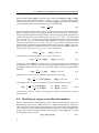
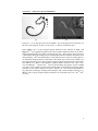
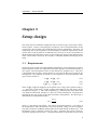
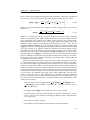
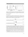
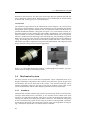
1
University of Twente EEMCS / Electrical Engineering Robotics and Mechatronics Realization of a Three-Dimensional Magnetically-Actuated Microrobotic System R.M.P. (Roel) Metz MSc Report Committee: Prof.dr.ir. S. Stramigioli Dr. S. Misra I.S.M. Khalil, PhD Dr.ir. L. Abelmann April 2013 Report nr. 008RAM2013 Robotics and Mechatronics EE-Math-CS University of Twente P.O. Box 217 7500 AE Enschede The Netherlands Abstract Minimal invasive surgery (MIS) aims to reduce patient trauma and recovery time. One field of research within MIS is the utilization of microrobots to diagnose and deliver drugs at hard-to-reach regions within the human body. These microrobots could have magnetic properties which allow us to control them by applying magnetic fields. The goal of this Master0 s thesis project is to develop a testbed to perform three-dimensional (3D) closed loop control of microrobots. Control of microrobots in 3D space is implemented using the developed MagneticallyActuated Robotic System (MARS). MARS has eight electromagnets which are used to generate almost uniform magnetic fields of 64.5 mT in magnitude, magnetic field gradients of 1.52 Tm−1 , and gradient of the squared magnetic fields of 127.1 mT2 mm−1 . These magnetic fields and gradients allow us to control paramagnetic microparticles, microjets and magnetotactic bacteria within a 3D space of maximum 2.4 mm3 . Feedback for the position controllers is provided by two microscopes with attached cameras which provide images at 50 frames per second. The images provided by the cameras are used by feature tracking algorithms to determine the position of the microrobot. Furthermore, MARS is equipped with an autofocusing system. The position and autofocusing controllers, and feature tracking algorithms are implemented on a real-time control platform. It is experimentally demonstrated that MARS is capable of achieving point-to-point position control of paramagnetic microparticles in 3D space. The position accuracy during the experiment is approximately 5.3 µm, the average velocity is 367 µms−1 , and the maximum velocity is 2 mms−1 . Also a self-propelled microjet is position controlled in 3D space. The position accuracy during this experiment is approximately 157 µm and the average velocity is 121 µms−1 . To our knowledge, we have for the first time demonstrated the closed loop control of microjets in 3D space. i ii CONTENTS CONTENTS Contents 1 Introduction 1.1 Contributions . . . . . . . . . . . . . . . . . . . . . . . . . . . . . . . . . . . . 1.2 Thesis organization . . . . . . . . . . . . . . . . . . . . . . . . . . . . . . . . . 1 3 3 2 Modeling of microrobots 2.1 Modeling of force controlled microrobots . . . . . . . . . . . . . . . . . . . 2.2 Modeling of torque controlled microrobots . . . . . . . . . . . . . . . . . . 5 5 6 3 Setup design 3.1 Requirements . . . . . . . . . . . . . . . . 3.2 Magnetic system . . . . . . . . . . . . . . . 3.3 Microscopic system . . . . . . . . . . . . . 3.3.1 Microscopes . . . . . . . . . . . . . 3.3.2 Cameras . . . . . . . . . . . . . . . 3.3.3 Illumination . . . . . . . . . . . . . 3.4 Mechanical system . . . . . . . . . . . . . 3.4.1 Autofocus . . . . . . . . . . . . . . 3.4.2 Vibration isolation table . . . . . 3.5 Electrical system . . . . . . . . . . . . . . . 3.6 Control system . . . . . . . . . . . . . . . . 3.6.1 Real-time software environment 3.6.2 Real-time hardware environment 3.6.3 Feature tracking software . . . . . 3.6.4 Autofocus implementation . . . . 3.6.5 Magnetic-based control system . 3.7 Realized system . . . . . . . . . . . . . . . . . . . . . . . . . . . . . . . . . . . . . . . . . . . . . . . . . . . . . . . . . . . . . . . . . . . . . . . . . . . . . . . . . . . . . . . . . . . . . . . . . . . . . . . . . . . . . . . . . . . . . . . . . . . . . . . . . . . . . . . . . . . . . . . . . . . . . . . . . . . . . . . . . . . . . . . . . . . . . . . . . . . . . . . . . . . . . . . . . . . . . . . . . . . . . . . . . . . . . . . . . . . . . . . . . . . . . . . . . . . . . . . . . . . . . . . . . . . . . . . . . . . . . . . . . . . . . . . . . . . . . . . . . . . . . . . . . . . . . . . . . . . . . . . . . . . . . . . . . . . . . . . . . . . . . . . . . . . . . . . . . . . . . . . . . . . . . . . . . . . 9 9 12 20 20 21 23 26 26 28 28 29 31 31 32 35 36 38 4 Experimental results 4.1 Experiments on the magnetic system . . 4.2 Experiment autofocus . . . . . . . . . . . 4.3 Experiments motion control . . . . . . . . 4.3.1 Motion control of a microparticle 4.3.2 Motion control of a microjet . . . . . . . . . . . . . . . . . . . . . . . . . . . . . . . . . . . . . . . . . . . . . . . . . . . . . . . . . . . . . . . . . . . . . . . . . . . . . . . . . . . . . . . . . . . . . . . . . . . . . . . 41 41 42 43 44 48 5 Conclusions 5.1 Conclusions . . . . . . . . . . . 5.2 Recommendations . . . . . . . 5.2.1 Design improvements 5.2.2 Future research . . . . . . . . . . . . . . . . . . . . . . . . . . . . . . . . . . . . . . . . . . . . . . . . . . . . . . . . . . . . . . . . . . . . . . . . . . . . . . . . . . . . 49 49 49 49 50 A Test Report TIMM400 . . . . . . . . . . . . . . . . . . . . . . . . . . . . 51 iii CONTENTS CONTENTS B CAD Drawings 55 C PI M-404 Datasheet 75 D Vibration damper datasheet 79 E Electronics 83 F Real-time software environments 85 G Optimal Controller 89 iv CHAPTER 1. INTRODUCTION Chapter 1 Introduction In the last 25 years, a major change in surgery has occurred: endoscopic surgery has revolutionized medicine by enabling surgeons to operate inside the human body without making large incisions (Morgenstern, 2008). Endoscopic surgery, also called minimally invasive surgery (MIS), has the advantage over open surgery that only small incisions have to be made. Small incisions reduce patients trauma, hospitalization and recovery time. Over the years many techniques of MIS have evolved. Surgical robots were developed which give the surgeon the ability to operate via small incisions on the patient. An example of a widely used surgical robot is the da Vinci® Surgical System (da Vinci® Surgical System, Intuitive Surgical® , Sunnyvale, California, USA). This system is shown in figure 1.1. In this system, the movements made by the surgeon at the master device are recorded, scaled and send in real-time to the slave device. The slave device operates the patient and sends a video-stream back to the master device. Another application of MIS, which uses even smaller incisions, is the use of flexible needles (Abayazid et al., In Press; Glozman and Shoham, 2007; Roesthuis et al., 2011, 2012). These flexible needles have a beveled tip which makes the needle bend when it is inserted into soft tissue. By controlling the orientation of the needle it can be steered inside the soft tissue. The control of the trajectory of the needle enables us to steer the needle around obstacles or organs. Figure 1.1: The da Vinci® Surgical System. Image courtesy of Intuitive Surgical® Inc. (Intuitive Surgical Inc., 2011) 1 A disadvantage of medical robots and flexible needles is that certain hard-to-reach areas within the human body are not accessible. This limitation is overcome by using microrobots as medical instrument. The use of microrobots as surgical instrument is still in an early conceptual stage. However, medical microrobots have the potential to revolutionize medicine by drug delivery or diagnose hard-to-reach areas in the human body (Nelson et al., 2010). These used microrobots have magnetic properties which enables us to control them by applying magnetic fields and gradients. Research has been done in modeling magnetic properties of these microrobots (Abbott et al., 2007; Pawashe et al., 2009). Also, different systems have been realized which are capable of controlling microrobots in three-dimensional (3D) space. More systems are provided in (Kratochvil et al., 2010; Sakar et al., 2012). The microrobots used in these system consist of (para-)magnetic bodies which require magnetic field gradients to move in the 3D workspace. Another type of microrobots have self-propulsion capabilities. Examples of this type of microrobots are microjets (Solovev et al., 2009) and spiral-type magnetic micromachines (Ishiyama et al., 2002). Microjets (figure 1.2(b)) are small hollow tubes in which a catalytic reaction with the fluid they are submersed in produces air bubbles. These air bubbles are used to propel the microjet through the fluid. The magnetic properties of microjet allow for the control by applying magnetic fields. Spiral-type micromachines have a spiral shape which screws the microrobot through the workspace by magnetically rotating the microrobot around its axis. Furthermore, biological microrobots are of interest for medical applications. Examples for these types of microrobots are magnetotactic bacteria (MTB) (figure 1.2(c)) and red blood cells with artificial tails. MTB propel themselves by using their flagella and can be magnetically controlled because of the magnetic nano-crystals in their membrane (Martel et al., 2009; Khalil et al., 2012b). Red blood cells with artificial tails are propelled and controlled by applying an oscillating magnetic field (Dreyfus et al., 2005). (a) (b) (c) Figure 1.2: Microrobots which are used in our setup (a) Paramagnetic particle. (b) Selfpropelled microjet (Solovev et al., 2009). (c) Magnetotactic bacterium Keuning et al. have developed a small sized magnetically-actuated system which is able to control paramagnetic microparticles in two-dimensional (2D) space (Keuning et al., 2011). This system is also used to characterize and control self-propelled microjets (Khalil et al., 2013a) and magnetotactic bacteria (Khalil et al., 2012b). Furthermore, interaction force estimation during manipulation of microparticles is implemented on this system (Khalil et al., 2012a). The goal of this Master0 s thesis project is to develop a testbed to perform 3D closed loop control of microrobots. Therefore, a system is realized that uses electromagnets to control different types and sizes of microrobots in 3D space. The microrobots are optically tracked using microscopes (with cameras attached). The camera images are also used as feedback for the control system. Furthermore, an autofocus system is implemented to provide focused images when the microrobots move in the fluid. 2 CHAPTER 1. INTRODUCTION 1.1 Contributions During this master thesis the following contributions are made: • Realization of a magnetically-actuated system which is capable of controlling microparticles, microjets, and MTB in 3D space, • Implementation of autofocusing on the setup for control of microrobot, • Implementation of a real-time magnetic-based control system, • Implementation of interaction force estimation during manipulation of microparticles (Khalil et al., 2012a), • Implementation of an optimal motion controller for paramagnetic microparticles in 3D space (Khalil et al., 2013b). 1.2 Thesis organization This thesis will start with modeling the magnetic properties of the microrobots in chapter 2. The design of the setup and its components is covered in chapter 3. Next, in chapter 4, some experiments which show the functionality of the setup are discussed. The thesis is concluded with conclusions and recommendations in chapter 5. 3 1.2. THESIS ORGANIZATION 4 CHAPTER 2. MODELING OF MICROROBOTS Chapter 2 Modeling of microrobots Modeling of the magnetic properties of microrobots (microparticles, microjets and MTB) is important for the design of magnetic systems and the control of the microrobots. Based on the magnetic properties of the microrobots, they can be divided into two categories: force and torque controlled microrobots. Microrobots which do not possess self-propulsion capabilities require an external force to pull them through a fluid. Therefore, these microrobots are force controlled. In our setup, the microparticles are part of this category. Microrobots which use self-propulsion to move through a fluid only require a magnetic torque to control their direction. These types of microrobots are part of the torque controlled microrobots. In our setup, microjets and magnetotactic bacteria (MTB) are controlled using external magnetic torque. 2.1 Modeling of force controlled microrobots The equation of the magnetic force (F(p) ∈ R3×1 ) acting on a magnetic dipole is given by F(p) = ∇(m(p) · B(p)), (2.1) where m(p) ∈ R3×1 is the induced magnetic dipole moment of the microparticle, and B(p) ∈ R3×1 is the induced magnetic field at point p ∈ R3×1 in the workspace. The microparticles used in our setup have a spherical geometry. According to Carpi and Pappone, the magnetic dipole moment of a spherical object can be determined as the volume integral of the induced magnetization (M(p) ∈ R3×1 ) (Carpi and Pappone, 2009): Z m(p) = M(p)d V, (2.2) V 4 πr 3 M(p). (2.3) 3 p In (2.2), V is the volume of the spherical microparticle with radius (r p ). The magnetization of the microparticle is related to the magnetic field strength (H(p) ∈ R3×1 ) by M(p) = χm H(p), (2.4) m(p) = where χm is the magnetic susceptibility constant (McNeil et al., 1995). The induced magnetization vector is always aligned with the induced magnetic field because of the isotropic properties of a spherical object. As a consequence, zero torque can be applied to the microparticles, and the microparticles are only subjected to pure forces. The 5 2.2. MODELING OF TORQUE CONTROLLED MICROROBOTS magnetic field strength (H(p)) is related to the magnetic field (B(p)) by, B(p) = µH(p), where µ is the permeability coefficient given by, µ = µ0 (1 + χm ), with µ0 the magnetic constant with value of 4π×10−7 TmA−1 . Substituting B(p) in (2.4) yields the following equation which relates the magnetization to the magnetic field: M(p) = χm µ B(p). (2.5) When the applied magnetic field reaches a certain magnitude, the magnetization of the particles material saturates, the magnetization becomes constant (ms ). The manufacturer (micromod Partikeltechnologie GmbH., Rostock, Germany) of the microparticles specifies the saturation mass magnetization to be 6.6 × 10⁻³ Am2 g−1 and the density to be 1.4 × 10⁶ gm−3 . Therefore, the saturation magnetization (ms ) is calculated to be 9.24×10³ Am−1 . Using a susceptibility of 0.17 (Khalil et al., 2012a) and the calculated saturation magnetization of ms = 9.24 × 10³ Am−1 in (2.5) yield the magnitude of the magnetic field at which the magnetization of the material saturates: kB(p)k = 79.9 mT. When the magnetization saturates and becomes constant, also the magnetic dipole moment becomes constant. In this case, (2.3) can be rewritten as m(p) = 4 3 πr p3 ms kB(p)k ≥ 79.9 mT. (2.6) Consequently, the magnetic force of (2.1) can be rewritten as F(p) = 4 3 πr p3 ms ∇(B(p)) kB(p)k ≥ 79.9 mT. (2.7) At magnetic fields (kB(p)k) less than 79.9 mT, the magnetization of the material of the particles is not saturated. Therefore, the magnetization depends on the magnetic field (B(p)). Substitution of (2.5) in (2.3) yields the expression for the magnetic dipole moment: 41 3 πr χm B(p) m(p) = kB(p)k < 79.9 mT. (2.8) 3µ p Substitution of (2.8) into (2.1) yields the following force-field map: F(p) = 41 3µ πr p3 χm ∇(BT (p)B(p)) kB(p)k < 79.9 mT. The magnetic force acting on a microparticle can be summarized as follows: ¨ 41 3 πr p χm ∇(BT (p)B(p)) for kB(p)k < 79.9 mT, 3µ F(p) = 4 3 πr m ∇(B(p)) for kB(p)k ≥ 79.9 mT. p s 3 (2.9) (2.10) This equation is used in section 3.2 to design the magnetic based control system for microparticles. 2.2 Modeling of torque controlled microrobots Microjets and MTB have self-propulsion systems which converts chemical energy into kinetic energy (Solovev et al., 2009; Martel et al., 2009). This propulsion system provides a thrust force which allows the microrobots to move in the fluid. The microrobots can be steered by controlling their orientation. The orientation can be controlled by applying magnetic torque on the microrobot. This magnetic torque (T(p) ∈ R3×1 ) acting on a magnetic body is given by T(p) = m(p) × B(p), 6 (2.11) CHAPTER 2. MODELING OF MICROROBOTS (a) (b) Figure 2.1: (a) A microjet with trail of bubbles. (b) An magnetotactic bacterium. In the inset, the magnetic crystals can be seen as a chain of small black dots. where m(p) ∈ R3×1 is the magnetic dipole moment of the microjet or MTB, and B(p) ∈ R3×1 is the applied magnetic field. The magnetic dipole moment can be determined experimentally or it can be calculated using (2.2). The structure of the microjets is formed by rolling up multiple layers of different materials (titanium, chromium, iron and platinum). The exact dimensions of the different layers after the rolling process are unknown which makes the calculation of the integral (2.2) inaccurate. Khalil et al. have determined the value of the magnetic dipole moment of the microjets experimentally (Khalil et al., 2013a). They found a magnetic dipole moment of 1.4 × 10⁻¹³ Am2 at 2 mT, 100 µms−1 , and 25 rads−1 . The size and quantity of magnetic crystals in MTB (see figure 2.1(b)) differs per bacterium which makes calculating the magnetic dipole moment via the volume integral inaccurate. Khalil et al. have characterized MTB using a flip-time technique, rotating-field technique and u-turn technique (Khalil et al., 2012b). The average magnetic dipole moment was calculated to be 3.59 × 10⁻¹⁶ Am2 at 2 mT. 7 2.2. MODELING OF TORQUE CONTROLLED MICROROBOTS 8 CHAPTER 3. SETUP DESIGN Chapter 3 Setup design The setup consists of different components such as motion stages, microscopes, illumination systems, cameras, electromagnets, and drivers. The overall performance of the system relies on the quality and synchronization of these components. Therefore, all components have to be designed or selected properly to fulfill the requirements of the system and to work together in an efficient way. This way it can be assured that we obtain maximum results of the system. In this chapter, the design of the different parts of the system will be discussed. The chapter is concluded with the final design of the setup. 3.1 Requirements The design of the system starts with defining requirements. The requirements concerning the magnetic system are important because this provides the main functionally of our system. The microparticles move in the fluid by the magnetic force. This force is provided by the magnetic system and has to overcome the drag force acting on the microparticle. The equation of motion for a microparticle in three-dimensional (3D) space can be written as: F x (p) − Fd x (ṗ) = mẍ, (3.1) F y (p) − Fd y (ṗ) = m ÿ, Fz (p) − F b − Fdz (ṗ) = mz̈, (3.2) (3.3) where F x (p), F y (p) and Fz (p) are the magnetic force acting on the particle along x, y-, and z-axis, respectively. Fd x (ṗ), Fd y (ṗ), and Fdz (ṗ) are the drag forces on the microparticle along x-, y-, and z-axis, respectively. F b is the buoyancy force which only acts along the z-direction. Further, m is the mass of the microparticle. The drag force depends on the type of flow of the fluid around the microparticle. The flow type is determined by the Reynolds number, Re = 2ρv r p η , (3.4) where ρ is the density of the fluid, v the velocity of the microparticle, r p the radius of the microparticle, and η the dynamic viscosity of the fluid. Using (3.4) for a microparticle with a diameter of 100 µm submerged in water with density of 998.2 kgm−3 and furthermore using a dynamic viscosity of 1 mPa.s. Assuming the velocity of the microparticle will not exceed 1 mms−1 , the Reynolds number is calculated to be less than 9 3.1. REQUIREMENTS 0.1. This Reynolds number yields a laminar flow type. In laminar flow conditions, Stokes law can be used to calculate the drag force. According to Stokes law, the drag force (Fd ) is a drag coefficient (α) times the velocity of the microparticle. The Reynolds number of our microparticle allows us to neglect inertial terms. We can now rewrite the equations of motion as: F x (p) − αẋ = 0, (3.5) F y (p) − α ẏ = 0, (3.6) Fz (p) − F b − αż = 0, (3.7) where α is given by, 6πηr p . The buoyancy force is given by, F b = V (ρ p − ρw )g, where V is the volume of the displaced water (volume of the microparticle), ρ p and ρw are the densities of the microparticle and water, respectively. g is the gravitational constant. Assuming low magnetic fields, we can substitute (2.9) and the expressions for F b and α in (3.5), (3.6), and (3.7): 41 3µ 41 3µ 41 3µ πr p3 χm πr p3 χm (BT (p)B(p)) − 6πηr p ẋ = 0, (3.8) (BT (p)B(p)) − 6πηr p ẏ = 0, (3.9) (BT (p)B(p)) − V (ρ p − ρw )g − 6πηr p ż = 0. (3.10) πr p3 χm ∂ ∂z ∂ ∂x ∂ ∂y Rewriting for magnetic field yields: ∂ ∂x ∂ ∂y ∂ ∂z 6πηr p ẋ (BT (p)B(p)) = (BT (p)B(p)) = (BT (p)B(p)) = , (3.11) 6πηr p ẏ , 41 πr p3 χm 3µ (3.12) 41 πr p3 χm 3µ V (ρ p − ρw )g + 6πηr p ż 41 πr p3 χm 3µ . (3.13) ∂ (BT (p)B(p)), ∂∂y (BT (p)B(p)), ∂x −1 2 −1 Designing a magnetic system for a velocity of 1 mms−1 , and ∂∂z (BT (p)B(p)) of 15.6 mT2 mm−1 , 15.6 mT2 mm , and 49.7 mT mm respectivily are required. The microjets and MTB require a torque to control their orientation. The torque is applied using magnetic fields, which can be expressed with (2.11). The magnetic dipole moment of the microjets and MTB is known. Therefore, we can calculate the magnetic torque for a certain magnetic field using (2.11). The magnetic torque has to overcome the drag torque to be able to rotate the microjet or MTB. The drag torque (Td ) can be expressed as Td = αω, (3.14) where α is the rotational drag coefficient, and ω is the angular velocity of the microrobot. The rotational drag coefficient is given by (Chemla et al., 1999) α= 10 πηL 3 3 ln L d + 0.92 d L −1 − 0.662 , (3.15) CHAPTER 3. SETUP DESIGN where L and d are the length and diameter of the microrobot, respectively. Substitution of (3.15) in (3.14) and equate the result to the magnetic torque of (2.11) yields km(p) × B(p)k = πηL 3 3 ln L d + 0.92 d L −1 − 0.662 ω. (3.16) While we are only interested in the magnitude of the magnetic field, (3.16) can be rewritten as −1 πηL 3 L d l n + 0.92 − 0.662 ω 3 d L kB(p)k = . (3.17) km(p)ksinφ Abbott et al. showed that for low magnetic fields the maximum torque is obtained when the angle between the applied magnetic field and the magnetic dipole moment of the microrobot is 45◦ (Abbott et al., 2007). For the microjets we can now substituting the boundary frequency (25 rad/s), the length (50 µm) and width (5 µm), the dynamic viscosity (1 mPa.s), the magnetic dipole moment (1.4 × 10⁻¹³ Am2 ), and angle between B(p) and m(p) is 45◦ in (3.17) which results in a required magnetic field (kB(p)k) of 19.1 mT. The experimentally determined boundary frequency of the MTB is 9.5 rad/s (Khalil et al., 2012b). When we substitute this and the length (5 µm) and width (0.2 µm) of the MTB, the dynamic viscosity (1 mPa.s), the magnetic dipole moment (3.59×10⁻¹⁶ Am2 ), and angle between B(p) and m(p) is 45◦ in (3.17), the required magnetic field (kB(p)k) is calculated to be 1.9 mT. The magnetic field required to rotate a MTB is lower than the magnetic field required for the microjets. Therefore, the magnetic field for the microjets is dominant, and will be used as design input for the magnetic system of our setup. Besides the requirements for the magnetic system, other requirements need to be set. The magnification of the microscopes can be specified by the field of view (FOV). It is devised that a FOV of approximately 20 to 25 times the size of the microrobot is sufficient. A larger FOV results in a lower magnification of the microrobot which can make the image processing more difficult. On the other hand, a smaller FOV results in a larger microrobot in the image, which makes the image processing easier, but limits the workspace of the microrobot. The size of the bacteria, microjets and microparticles is 5 µm, 50 µm, and 100 µm respectively. This results in FOV of 0.1 mm × 0.1 mm, 1 mm × 1 mm, and 2 mm × 2 mm. Furthermore, an autofocus system is required to keep the microrobots in focus while moving in the fluid. The last requirement is that the control system is implemented on a real-time platform. The requirements can be summarized as follows: • Gradients of the squared magnetic field ∂ (BT (p)B(p)) ∂z ∂ (BT (p)B(p)), ∂∂y (BT (p)B(p)), and ∂x 2 −1 2 −1 of 15.6 mT2 mm−1 , 15.6 mT mm quired, respectively. and 49.7 mT mm are re- • A magnetic field (kB(p)k) with magnitude of 19.1 mT is required. • The microscopic system should provide FOV of about 0.1 mm × 0.1 mm, 1 mm × 1 mm, and 2 mm × 2 mm when controlling the MTB, microjets, and microparticles, respectively. • An autofocus system is required. • The control system should be implemented on a real-time platform. 11 3.2. MAGNETIC SYSTEM r d c Coils Figure 3.1: Schematic representation of the cross-section of a coil configuration. A Helmholtz configuration, which can generate uniform magnetic fields in the center (c) between two coils, can be realized by placing the coils at a distance (d) equal to the radius of the coil (r). The electrical current should be applied in the same direction in the coils. A Maxwell configuration, which can generate uniform magnetic field gradient in the center p (c) between the coils, can be realized by placing the coils at a distance (d) equal to 3 times the radius of the coils (r). The electrical current should be applied in the opposite direction in the coils. 3.2 Magnetic system The magnetic system provides magnetic fields and gradients necessary to control the microrobots. In general, magnetic fields and gradients generated with electromagnets have the disadvantage of non-linearity. One way to reduce the effects of non-linearity is to create uniform fields and gradients (Yesin et al., 2006). Uniform fields and gradients can be generated by special configurations of the coils. Such a configuration is the Helmholtz configuration which generates uniform fields in the center of the Helmholtz configuration between two identical coils. In figure 3.1 a schematic representation of a coil configuration is shown. The coils are placed on the same axis and at a distance (d) equal to the radius of the coil (r). Applying currents to the coils in the same direction generates a uniform field close to the center (c). A similar configuration is the Maxwell configuration which generates uniform gradients close to the center of the Maxwell configuration p between two coils. In the Maxwell configuration, the coils are separated (d) with 3 time the radius of the coil (r). The currents are applied in opposite directions in the coils. A major disadvantage of these configurations occurs when using them for control in 3D space. In this case, the distance of a second set of coils equals the diameter of the coils in the first set, the third set will become even larger. When also two microscopes, illumination modules and reservoir holder have to be placed in the same space as the coils, there is practically no space for Helmholtz and/or Maxwell configuration of coils in our setup. However, reducing the non-linearity in the magnetic fields by arranging the coils in an optimal way is still of great interest. Therefore, we design the configuration of the coils in a way that the fields and gradients are close to the preferred uniform magnetic fields and gradients. The coils arrangement we designed is shown in figure 3.2(a). The eight coils are placed in an upper and lower set of both four coils. The upper and lower set of coils are placed at 45◦ and −45◦ with respect to the horizontal plane, respectively. In this configuration of coils, the magnetic fields of the four upper coils can be combined to provide sufficient gradients to lift the microparticles, while also sufficient space is created to position a microscope at the top. The side view microscope is positioned 12 CHAPTER 3. SETUP DESIGN (a) (b) Figure 3.2: Design of the configuration of the magnetic system. (a) Model in SolidWorks (Dassault Systèmes SolidWorks Corp., Waltham, Massachusetts, USA). This model is used to design the physical dimensions of the magnetic system. In the model eight coils with cores are used. On the left and the top microscopes (1) are positioned. Opposing these microscopes, illuminations modules (2) are placed. In the center the reservoir holder (3) is positioned between the coils (4). (b) Finite element (FE) model in Comsol Multiphysics® (COMSOL Inc., Burlington, U.S.A). This model is used to perform finite element calculations on the magnetic fields. between the upper and lower set of coils. At a 90◦ angle in the horizontal plane, the reservoir holder can be placed. It is desirable to keep the distance of the coils to the center of the workspace small, since magnetic fields are stronger close to the coils than further away from the coils. However, besides the coils also other components, like two microscopes, two illumination modules and a reservoir holder have to be placed in the same workspace. Therefore, the coils are placed at a larger distance from the center of the workspace. The tradeoff is that the fields are weaker in the center of the workspace. By using more coils and placing cores in the coils, the combined magnetic fields are still sufficient to provide the required magnetic fields and gradients. In figure 3.2(b) a finite element (FE) model made in Comsol Multiphysics® (COMSOL Inc., Burlington, U.S.A) is shown. The FE model allows us to do calculations on the magnetic fields and therefore it is used to check the uniformity, magnitude and gradient of the magnetic fields. These properties are checked by applying currents to the coils and plotting the magnetic fields. In figure 3.3, figure 3.4, and figure3.5, the magnitude and direction of the magnetic field in the x y-, xz-, and yz-plane are shown when a magnetic field is created along the x-, y-, and z-direction. The magnetic fields are almost uniform. The standard deviation of the magnetic field magnitude in the workspace is 0.22 mT, 0.24 mT and 0.07 mT when creating a magnetic field in x-, y-, and z-direction, respectively. The standard deviation of the direction of the magnetic fields is 0.32◦ , 0.28◦ , and 0.20◦ when a magnetic field is created along x-, y-, and z-direction, respectively. Furthermore, the magnitude of the magnetic fields is close to the required 20 mT while the applied currents lower than 0.7 A. Preliminary simulations of the magnetic field gradients showed that in the currently designed system the gradients do not meet the requirements. Especially the gradients in z-direction are not sufficient to provide the required lift to overcome gravity. While the current design of the magnetic system is capable of providing close to uniform fields, we decided to design a configurable system. In the case of using microjets and 13 3.2. MAGNETIC SYSTEM XY-plane XY-plane 1 kBk [mT] 17.8 y [mm] 17.6 17.4 17.2 1 0 y [mm] −1 −1 0 0 −1 1 −1 x [mm] 0 x [mm] 1 XZ-plane XZ-plane 1 kBk [mT] 17.8 z [mm] 17.6 17.4 17.2 1 0 z [mm] −1 −1 0 0 −1 1 −1 x [mm] YZ-plane 0 x [mm] 1 YZ-plane 1 kBk [mT] 17.8 z [mm] 17.6 17.4 17.2 1 0 z [mm] −1 −1 0 1 y [mm] 0 −1 −1 0 y [mm] 1 Figure 3.3: Magnitude (left) and direction (right) of the magnetic field on the x y-, xzand yz-plane in the workspace when a magnetic field in x-direction is created. The applied current vector is [0.05195 -0.6196 -0.03537 0.6695 0.4163 -0.3964 -0.4284 0.4025]. The images show that the magnetic field is close to uniform in the workspace. The standard deviation of the magnetic field and its direction in the workspace is 0.22 mT and 0.32◦ , respectively. 14 CHAPTER 3. SETUP DESIGN XY-plane XY-plane 1 kBk [mT] 19.6 x [mm] 19.4 19.2 19 1 0 y [mm] −1 −1 0 0 −1 1 −1 x [mm] 0 y [mm] 1 XZ-plane XZ-plane kBk [mT] 1 z [mm] 19.5 19 1 0 z [mm] −1 −1 0 0 −1 1 −1 x [mm] YZ-plane 1 YZ-plane 1 z [mm] 19.5 kBk [mT] 0 x [mm] 19 1 0 z [mm] −1 −1 0 1 y [mm] 0 −1 −1 0 y [mm] 1 Figure 3.4: Magnitude (left) and direction (right) of the magnetic field on the x y-, xzand yz-plane in the workspace when a magnetic field in y-direction is created. The applied current vector is [-0.6528 0.06854 0.6357 -0.03481 -0.4904 -0.4797 0.4758 0.5045]. The images show that the magnetic field is close to uniform in the workspace. The standard deviation of the magnetic field and its direction in the workspace is 0.24 mT and 0.28◦ , respectively. 15 3.2. MAGNETIC SYSTEM XY-plane XY-plane 1 y [mm] kBk [mT] 18.4 18.2 18 1 0 y [mm] −1 −1 0 0 −1 1 −1 x [mm] 0 x [mm] 1 XZ-plane XZ-plane 1 z [mm] kBk [mT] 18.4 18.2 18 1 0 z [mm] −1 −1 0 0 −1 1 −1 x [mm] YZ-plane 0 x [mm] 1 YZ-plane 1 z [mm] kBk [mT] 18.4 18.2 18 1 0 z [mm] −1 −1 0 1 y [mm] 0 −1 −1 0 y [mm] 1 Figure 3.5: Magnitude (left) and direction (right) of the magnetic field on the x y-, xzand yz-plane in the workspace when a magnetic field in z-direction is created. The applied current vector is [0.3353 0.3846 0.3237 0.3641 -0.358 -0.4154 -0.3401 -0.4217]. The images show that the magnetic field is close to uniform in the workspace. The standard deviation of the magnetic field and its direction in the workspace is 0.07 mT and 0.20◦ , respectively. 16 CHAPTER 3. SETUP DESIGN XY-plane 1 10 y [mm] ∂ (BT B) ∂x [mT2 mm−1 ] XY-plane 5 0 1 0 y [mm] −1 −1 0 0 −1 1 −1 x [mm] 1 XZ-plane 1 20 z [mm] ∂ (BT B) ∂x [mT2 mm−1 ] XZ-plane 0 x [mm] 10 0 1 0 z [mm] −1 −1 0 1 x [mm] 0 −1 −1 0 x [mm] 1 Figure 3.6: Magnitude (left) and direction (right) of the magnetic field gradient in x-direction on the x y-, and xz-plane in the workspace when a magnetic field gradient in x-direction is created. The applied current vector is [0.009157 0 0.004817 1.113 0.7172 0 0 0.7071]. The images show that the magnetic field gradient is not uniform in the workspace. In the x y-plane, the magnetic field gradient is constant along the x-axis and increasing with a constant slope along the y-axis. The direction of the magnetic field gradient is along the x-axis. In the xz-plane, the magnetic field gradient is increasing along x- and z-axis. The direction of the magnetic field gradient is in x- and z-direction, which could be beneficial while this provides additional lift in zdirection. 17 3.2. MAGNETIC SYSTEM XY-plane 1 10 x [mm] ∂ (BT B) ∂y [mT2 mm−1 ] XY-plane 0 1 0 y [mm] −1 −1 0 0 −1 1 −1 x [mm] 1 YZ-plane 1 10 z [mm] ∂ (BT B) ∂y [mT2 mm−1 ] YZ-plane 0 y [mm] 0 1 0 z [mm] −1 −1 0 1 y [mm] 0 −1 −1 0 y [mm] 1 Figure 3.7: Magnitude (left) and direction (right) of the magnetic field gradient in xdirection on the x y-, and yz-plane in the workspace when a magnetic field gradient in y-direction is created. The applied current vector is [0 0 1.095 0 0 0 0.7461 0.7429]. The images show that the magnetic field gradient is not uniform in the workspace. In the x y-plane, the magnetic field gradient is increasing in y-direction with a constant slope and its direction is primarily along the y-axis. In the yz-plane, the magnetic field gradient is increasing along y- and z-axis. The direction of the magnetic field gradient is in y- and z-direction, which could be beneficial while this provides additional lift in z-direction. 18 CHAPTER 3. SETUP DESIGN XZ-plane 1 46 z [mm] ∂ (BT B) ∂z [mT2 mm−1 ] XZ-plane 44 42 1 0 z [mm] −1 −1 0 0 −1 1 −1 x [mm] 1 48 z [mm] [mT2 mm−1 ] 1 YZ-plane YZ-plane ∂ (BT B) ∂z 0 x [mm] 46 44 1 0 z [mm] −1 −1 0 1 y [mm] 0 −1 −1 0 y [mm] 1 Figure 3.8: Magnitude (left) and direction (right) of the magnetic field gradient in z-direction on the xz-, and yz-plane in the workspace when a magnetic field gradient in z-direction is created. The applied current vector is [0.9475 0.9859 0.9684 0.9894 0 0 0 0]. The images show that the magnetic field gradient and its direction are close to uniform in the workspace. The magnetic field gradients are around 45 mT2 mm−1 which shows that configurable design is capable of creating sufficient magnetic field gradients in the z-direction to provide lift for the microparticle. 19 3.3. MICROSCOPIC SYSTEM MTB, the current coil configuration is used to provide approximately uniform fields. When high gradients of the magnetic field are required to control the microparticles, the magnetic system is slightly modified. The cores in the upper four coil are placed closer to the center of the workspace, and a spacer of 5 mm is added to lift the upper four coils. The magnetic field gradients in the workspace are shown in figure 3.6, figure 3.7, and figure 3.8 when a magnetic field gradient is created along the x-, y-, and z-axis, respectively. The images show that the magnetic field gradients are not uniform when a magnetic field gradient is created in x- and y-direction. In z-direction the magnetic field gradient is close to uniform. It can also be seen that because of the configurable design the system is capable of creating the required magnetic field gradient in z-direction. In the x- and y-direction the magnetic field gradients can be increased by increasing the current to meet the requirements. In addition, a better gradient-current mapping can improve the magnitude and direction of the magnetic field gradients. 3.3 Microscopic system The goal of the setup is to control microrobots (microparticles, microjets and MTB) while they move in fluid. Controlling the microrobots requires a position feedback. An option is to use visual feedback. The size of our robots, especially the bacteria, requires high magnification of the workspace. This feedback can be achieved by the use of a microscopic system. This system consists of a lightweight microscope with an attached camera and an illumination system. These components are discussed in this section. 3.3.1 Microscopes An optical microscope is a device which uses a light source and a set of lenses to visualize a sample at a magnified level. The magnification depends on the kind of lenses/objectives used in the microscope. An important property of an objective, besides the magnification, is the Numerical Aperture (N A). The numerical aperture is a dimensionless number that describes the maximum acceptance cone of an objective and can be calculated as follows: N A = nsinθ , (3.18) where n is the index of refraction of the medium in which the system operates. The angle θ is the half-angle of the top of the maximum cone at which the objective can accept light; it is the angle between the focal length and half the clear aperture. Another important property is the resolving power of the microscope. This is the ability of the microscope to distinguish between two adjacent structural details. Therefore, the resolving power is a measure for the size of details that can be made visible with the microscope. The resolving power is also called the resolution of the microscope. The resolution (d) depends on the wave length (λ) of the used light and the N A of the objective and is given by d= λ . (3.19) 2N A A commercial available miniature microscopic system is the Technisch Industrielles Miniatur Mikroskop with 400 times magnification (TIMM400) from SPI GmbH, Oppenheim, Germany. This microscope is only 22 mm in diameter, 155 mm long and weights 100 g. In the basic configuration, it has a variable magnification up to 400X which can be extended with additional modules like lenses and spacers. The system 20 CHAPTER 3. SETUP DESIGN also incorporates a 5 megapixel (MP) camera with an analog or USB interface which can achieve up to 25 fps. Unfortunately, after a short testing period it is concluded that this microscopic system is not sufficient to be used in the microrobotic setup: the frame rate is too low, the image quality is poor at high magnification and the price is too high (>€4000). In appendix A a test report is included. Another system that does meet our requirements is the Qioptiq Optem Zoom125C microscope system (Qioptiq, Luxembourg, Luxembourg). This is a modular system which can be composed to the needs in the project with a basis part that allows up to 6X magnification. It can be combined with Mitutoyo M Plan Apo objectives (Mitutoyo Corporation, Kawasaki, Japan), and c-mount cameras can be connected to proved video feedback to the control system. By combining different objectives with the zoom basis part and an additions 2X magnifying part, the total zoom range becomes 4X up to 120X, which should be sufficient to image microparticles as well as bacteria. The FOV which can be attained which this microscope are experimentally determined and shown in table 3.1. Microscope with 2X objective Zoom value of the microscope 0.6 1.0 2.0 3.0 µm/pixel 2.33 1.40 0.69 0.47 Image height [µm] 2385.3 1434.0 481.0 481.0 4.0 0.35 360.4 5.0 0.28 288.3 6.0 0.23 240.2 Microscope with 10X objective Zoom value of the microscope µm/pixel 0.97 0.58 0.29 0.20 Image height [µm] 991.7 595.7 299.9 200.0 0.15 149.8 0.12 120.1 0.10 100.1 Table 3.1: Field of view of the microscope at different setting The resolution of the system is checked to ascertain that it is sufficient for our application. Equation 3.19 is used in combination with a Mitutoyo M Plan Apo 10X objective (Mitutoyo Corporation, Kawasaki, Japan) and a green LED light source to calculate the resolution of the system. Due to the long working distance of the objective, the numerical aperture is relatively low: N A = 0.28. In section 3.3.3 the light source is discussed; the power LED emits light in a range around 520 nm. Using these values in (3.19), a maximum resolution of the system of d = 0.9 µm is found. It is presumed that this is high enough to view 5 µm bacteria, and therefore no problems are to be expected with viewing the larger microrobots. 3.3.2 Cameras In our setup, cameras are required to provide the visual feedback from the microscopes to the control system. The frame rate of the cameras determine the bandwidth of our controller. Keuning et al. (2011) have built a system that is capable of controlling microparticles in 2-dimensional space. The performance of this system is limited by the bandwidth of the controller which is 10 Hz. We want to avoid this limitation and therefore aim for a bandwidth of 100 Hz. This means that the cameras should have a frame rate of at least 100 fps. Furthermore, the resolution of the used cameras partially determine the position accuracy of the controlled microrobots. The system described by Keuning et al. (2011) uses a camera with resolution of 768 × 1024. For our system we want at least to match this resolution and therefore aim for cameras with a resolution of round 1 MP. While there is hardly any color in the scenery of the microrobots, 21 3.3. MICROSCOPIC SYSTEM Figure 3.9: Basler Aviator light sensitivity, from user manual (Basler AG, 2010). The camera is most sensitive to light with a wave length around 500 nm, which corresponds with green light. By designing an illumination system with a green light source the camera will produce bright images. there is no need for color cameras, monochrome cameras are sufficient. This also decreases the data throughput by a factor 3 which is beneficial for the control system. Another requirement for the cameras is that they should have an interface which is compatible with the control system. In section 3.6.1 the realtime control platform is chosen to be xPC Target™. This system can only be used in combination with USB and CameraLink™ cameras. The high resolution and frame rate requirement, reject the use of USB cameras, so a CameraLink™ interface is required. A final requirement is the mechanical interface type. In section 3.3.1 the microscopes are described, which have a C-mount interface for the camera; the cameras should be compatible with this interface. Requirements of our system are summarized as follows: • A minimal frame rate of 100 fps is required • A camera resolution of 1 MP is required • The cameras should provide monochrome images • The cameras should have CameraLink™ interface • The cameras should be compatible with the C-mount connection. The xPC Target™ system drivers support only one framegrabber for CameraLink™ cameras which are from the brand Bitflow. The supplier of these framegrabbers suggested to use Basler cameras because these are very compatible with their framegrabbers. The Basler camera which is closest to our needs is the Basler Aviator A1000120km (Basler AG, Ahrensburg, Germany). This camera has a 1 MP monochrome sensor and can deliver 120 fps. The monochrome sensor makes the camera most sensitive to green light (wave length around 500 nm) as shown in figure 3.9. The sensitivity for a specific frequency range can be very beneficial when designing the illumination accordingly. Finally, the data interface and connection type are according our requirements. 22 CHAPTER 3. SETUP DESIGN 3.3.3 Illumination In the setup, an optical microscope is used which requires a light source to be able to visualize the sample. Illumination of microscopic systems can be divided into two major classes: direct and indirect illumination. Direct illumination, are also called background illumination, uses absorption of light by the sample to make the sample visible in the camera image (figure 3.10) left. The indirect illumination principle uses the reflection of light at the sample the make the sample visible in the camera image (figure 3.10 right). The indirect illumination can be implemented using ring illumination which is placed around the microscope objective or by using coaxial illumination. Coaxial illumination is implemented by a semi-transparent mirror inside the microscope which reflects the light from the source directly out of the objective towards the sample. In general, the advantage of indirect illumination is that also surfaces of solid objects can be made visible. A disadvantage is that samples with low reflection (like transparent tissue) are less visible than sample which are very reflective. Microscope objective Sample holder Figure 3.10: Schematic representation of two types of illumination principles. Left: direct illumination. Right: indirect illumination. In our system also less reflective microrobots will be used, therefore direct illumination (left) is the best option for our setup. In direct illumination different types can be distinguished, like critical illumination and the Köhler illumination (Köhler, 1893). Also more advanced techniques are available like phase contrast and differential interference contrast. These techniques are too complex to use in a custom build system like the microrobotic system and therefore will not be discussed here. Critical illumination is the simplest type: an image of the light source is projected on to the sample using a lens. This lens concentrates all the light emitted by the source in the field of view which yields a very bright illuminated sample. A downside of focusing the light is that it can cause an uneven illumination of the sample when not aligned or positioned properly. Another disadvantage is that often the light source itself is visible in the image. Realizing a highly even illumination of the sample can be achieved by an inventive system introduced by August Köhler (Köhler, 1893). This system uses multiple lenses and diaphragms to create a parallel beam of light which yields an even illuminated sample without a visible projection of the source in the image. Several system are commercial available, but they all have the same disadvantages: it is hard to fit them in our system design and they are relatively expensive. Also a lot of these systems use indirect lighting while we want to use direct lighting to achieve better contrast images and to be able to view bacteria. To avoid the disadvantages of commercial available system, a custom build illumination system will be used. This system will use the more simple critical illumination principle. In figure 3.11 a schematic 23 3.3. MICROSCOPIC SYSTEM Sample holder Microscope objective Focus lens Collector lens θ α LED Figure 3.11: Components and light path of an critical illumination system. The light from the LED is collected by the collector lens and focused into the sample by the focus lens. The microscope objective receives the light and projects it onto the sensor of the camera. The angle (α) should at least match the angle (θ ) to fully illuminate the sensor. representation is shown of the illumination system. A power light emitting diode (LED) will be the light source. The light of the LED is collected by the collector lens. This lens will converge the light to a more or less parallel beam. This parallel beam is then focused by another lens into the sample. The light then passes to the microscope objective, which will project the image onto the sensor of the camera. For the sensor to be fully illuminated, the angle (α) in figure 3.11 should match the angle (θ ) of the microscope objective. To make sure the sensor is indeed fully illuminated, the angle (α) can be chosen slightly larger than (θ ). It should be noted that when (α) is larger than (θ ) it results in a lower overall illumination intensity on the sensor because the light is only partially projected on the microscope objective. Light source The light source for the illumination system will be a 3 W power LED. Major advantages of a power LED over other light sources, like halogen light bulb, are the lower heat dissipation and light emission in a specific frequency range. The lower heat dissipation results in less unwanted heating of the sample. While in the setup a fluid reservoir is used, the fluid could heat up and therefore unwanted currents in the fluid could occur. So a low heat dissipation is preferred. In section 3.3.2 the to be used cameras are discussed and in figure 3.9 the light sensitivity of the camera is shown. The cameras are most sensitive to green light and therefore the LED will have to match this property to yield an optimal camera-LED combination. A power LED which has the desired properties is the Avago 3 W Green Power LED Light Source from the ASMT-Ax3x series (Avago Technologies, San Jose, California, United States). In figure 3.12(a) the intensity of the illumination is shown. Comparing figure 3.9 and 3.12(a) it can be seen that the wave length ranges match. Furthermore, in figure 3.12(b) the light intensity over the emitting angle of the LED is shown. The intensity is relatively constant over the emitting angle which yields a uniform illumination of the sample when combined with a collector lens. The LED will be driven by a special driver which can vary the light intensity. 24 CHAPTER 3. SETUP DESIGN (a) (b) Figure 3.12: Specification of the Avago 3W Green Power LED Light Source from the ASMT-Ax3x series (Avago Technologies, San Jose, California, United States). Images from datasheet (Avago Technologies, 2011). (a) Emitting wavelength. (b) Light intensity over emitting angle. Microscopic lenses Two different lenses are needed for the illumination system. The first is to collect the light from the LED and the second to focus the light into the sample (see also figure 3.11). For collecting the light a condenser lens can be used. This lens can be chosen by f-number (written as f /# or N ). This f-number is defined as the ratio between focal length ( f ) and diameter of the entrance pupil (D): N= f D . (3.20) The f-number also defines the angle at which light can be accepted. From the geometric relation the angle can be written as: D θ = arctan . (3.21) 2f By rewriting this equation it can be applied to equation 3.20 which yields an equation for the f-number expressed in the angle: N= 1 2 tan θ . (3.22) While the LED is emitting light at approximately 120◦ (see figure 3.12(b)) the f-number is calculated to be 0.29. For this f-number no condenser lenses are available. Also no power LEDs with different emitting angle can be found. The conclusion that can be drawn is that the combination of LED and condenser lens cannot be optimized. Therefore, the condenser lens will be chosen according other requirements; in this case the maximum dimensions of the illumination system. This yields an aspheric condenser lens with outer diameter of 24 mm and an f-number of 0.8. The position of the power LED with regard to the collector lens has to be determined experimentally. The optimal position should yield a parallel beam of light after passing through the collector lens. When this position is determined an enclosure can be designed with these dimensions. The lens to focus the light can be chosen by N A of the microscope objective. The only limitation that the lens should also fit in the illumination module, which limits its 25 3.4. MECHANICAL SYSTEM diameter to about 25 mm. The N A of the microscope objective (M Plan Apo 10X, Mitutoyo, Kawasaki, Japan) is 0.28. Different lenses are available with an outer diameter of 25 mm and a N A of ≥ 0.31 at a reasonable price. Construction The schematic representation of the illumination system of figure 3.11 is the basis for the design of the illumination system. After preliminary test to determine the optimal LED position for the specific condenser lens, in cooperation with Islam Khalil an adjustable illumination module is designed (see figure 3.13). This module consists of a threaded cylinder. In this cylinder the power LED is mounted on a heat sink and the lenses are fixed at seats in the cylinder wall. The threaded cylinder sits in a larger nut. The nut is connected via ball bearing to the mounting ring. The mounting ring will be fixed to the magnetic system and also constrains the rotating motion of the cylinder by a plug. By rotating the nut by hand, the threaded cylinder will make a linear motion. This makes it possible to adjust the focus point of the illumination. The computer-aided design (CAD) drawings can be found in appendix B. (a) (b) Figure 3.13: Adjustable illumination module. (a) Photograph of the module. (b) Crosssection view of computer-aided design model. 3.4 Mechanical system The setup consists of lots of mechanical components. These components have to be bought, machined or 3D-printed. Most of these parts don’t have special design issues and therefore will not be discussed in this section. The technical drawings can be found in appendix B. However, two parts need special attention. These parts are the autofocus mechanism and the table damping and will be discussed hereafter. 3.4.1 Autofocus Commercially available autofocusing systems for microscope often use advanced microscopes with internal focus correction, or use external devices which track video signals or use reflected laser beams. Also, these systems are designed for ‘normal’ microscope use and not for tracking microrobots in 3D space. This makes the integration of such an autofocusing system in our setup very hard or even impossible. Therefore, we decided to design our own autofocusing system. This way the problem of integrating a commercial system into our control system is nullified. 26 CHAPTER 3. SETUP DESIGN The autofocusing system can be implemented using two different approaches: moving the objective of the microscope and hereby changing the focal distance, or moving the complete microscope assembly and hereby keeping the distance between object and microscope fixed while the focus distance is retained. The method of moving the objective of the microscope will yield faster autofocusing than moving the microscope assembly because less mass has to be moved. The downside is that the microscope has to be equipped with internal focus correction when using no infinity-corrected lenses. When using infinity-corrected objective the magnification will be changed be moving the objective because also infinity-corrected objective will not yield a perfect parallel beam. Also, while the magnification is not fixed, it is very hard to calibrate the system. The method of moving the microscope assembly does not have these disadvantages and with a powerful stage also the slower autofocusing can be fixed. Moving the microscope assembly seems to be the best option for the microrobotic setup. The microscope assembly is moved by a linear stage. This stage needs to fulfill some requirements concerning load capacity, push/pull force, applicable moment, backlash and control interface. First of all, the microscope assembly is estimated to have a mass of 2 kg (≈ 20 N). This yields a minimum load capacity of 20 N for the horizontally mounted stage. For the vertically mounted stage this yields a minimum push/pull force of 20 N. The center of mass of the load will be at a distance from the stage, which yields a moment on the stage. The distance between the stage and the center of mass is about 63 mm. This yields a minimally allowable moment on the stage of 20 × 63 = 1260 Nmm. Besides load capacity and so forth, a very important feature is the backlash of the stage. Especially for the bacteria, because of their very small size, this can be a critical requirement. In a situation where a bacterium is being tracked when swimming away for the camera and suddenly changes direction 180◦ the microscope has to follow the bacterium to keep it in focus, but the backlash in the drive chain could make that the bacterium is outside the focus depth of the microscope before the stage travel direction is reversed. To prevent this, the backlash should be limited. The depth of focus of the Mitutoyo M Plan 10X Apo objective (Mitutoyo Corporation, Kawasaki, Japan) we use in our setup is 3.5 µm. Practically the bacterium is still visible if it is within a range of approximately 5 times the depth of focus, which is 18 µm. It is expected that when the backlash of the stage is lower than this 18 µm it should be able to catch up with the bacterium. Another requirement is the travel range of the stage. While the field of view of the camera at the lowest magnification of the microscope is 2.5 mm by 2.5 mm, the stage should be able to travel at least 2.5 mm so the complete workspace can be covered. Obviously, a larger travel range is preferred to make it easier for the user to find the center of the workspace without having to reposition the microscope assembly by hand. Therefore, the minimal travel range is thought to be 10 mm. The last requirement is that the stage interface is compatible with the motor controllers we are aiming to use or that the supplied stage controller is compatible with control hardware (MathWorks® xPC Target™). The requirements of the autofocusing system are summarized as follows: • A minimal load capacity 20 N is required. • A moment of 1260 Nmm should be applicable. • A minimal travel range of 10 mm is required. • A maximal backlash of 18 µm is required. • The stage should be compatible with motor control and its interface. A linear stage that needs these requirements is the PI M-404.2DG (Physik Instrumente (PI) GmbH & Co.KG, Karlsruhe, Germany). The datasheet can be found in 27 3.5. ELECTRICAL SYSTEM appendix C. This stage has a travel range of 50 mm, a load capacity of 200 N and a backlash of 2 µm. The control interface is supported by the motor controllers (Elmo Whistle) we are using. The maximum applicable moment on the stage is not specified, but the supplier assured us that the expected load will not cause any problems. 3.4.2 Vibration isolation table The robots which will be used in the setup are very small: microparticle are about 100 µm, microjet about 50 µm and bacteria are the smallest with length of about 5 µm. The small size makes the use of microscopes necessary. The design of the microscopic system is discussed in section 3.3. When using microscopes it is important to have a stable platform for the microscope and the sample. The high magnification causes even small vibrations from the surrounding environment to influence the images acquired by the cameras on the microscopes. A good solution to reduce unwanted vibrations is placing the microscopic system on an optical table with vibration isolating supports (actively or passively damped). Unfortunately, there is limited space available in the medial robotics lab, so an optical table assembly is not an option for the moment. Therefore we decided to use a smaller optical breadboard, which has some build-in vibration damping, and place this on small vibration isolators. The necessary stiffness (k) of the vibration isolators is calculated by describing the system as a mass-spring system. The first eigenfrequency (ω) can be written as: v tk . (3.23) ωn = m It is expected that vibrations with a frequency of 2 Hz are acceptable in the system, higher frequency vibrations should be damped. Therefore, we can state that the first eigenfrequency should approximately 2 Hz. Furthermore, it is estimated that the setup (including breadboard) has a mass (m) of about 70 kg. According to (3.23) a total stiffness of 280 Nm−1 is required for the vibration isolators. Four vibration isolators supported the setup, so the stiffness of the individual vibration isolator can be added. This makes that a single vibration isolator should have a stiffness of about 70 Nm−1 . Supplier Paulstra has a variety of vibration dampers in the Radiaflex® series (Paulstra SNC, Levallois-Perret Cedex, France). In appendix D the datasheet is included. In this datasheet the stiffness of the dampers is not specified; only the maximum load and the corresponding deflection are mentioned. When assuming a constant stiffness of the damper, the stiffness (k) can be calculated using the load (F ) and deflection (u): k= F u . (3.24) Calculating the stiffness of multiple dampers in the Radiaflex® series, one of the dampers (reference number 511312) has a stiffness closed to the required stiffness and its dimensions will fit nicely in the setup. With a specified load of 70 daN and corresponding deflection of 8 mm the stiffness becomes 87.5 Nm−1 . This is more than the required 70 Nm−1 . Recalculating the eigenfrequency of the system using (3.23) and this higher stiffness, yields a first eigenfrequency of 2.2 Hz which is also acceptable. 3.5 Electrical system The electrical system of our setup consists of several key components. We need drives for the coils and stages, drives for the LED’s of the illumination and power supplies. 28 CHAPTER 3. SETUP DESIGN For safety reasons we also installed an emergency break switch. The schematics of the power circuit of the system can be found in appendix E. The coils of our system are driven by a current supply, the stages require a motor controller. Elmo Whistle motor drives can act as motor controllers and current supplies depending on the mode they are put in. Using Elmo Whistle drives allows us to control the stages as well as the current for the coils with the same type of driver. Using only one type of drive in the system is an advantage because only one type of communication has to be implemented. The DC motors in the stages will draw a maximum of 0.49 A, so the smallest Elmo Whistle drive can be chosen: the Elmo Solo Whistle 1/60 (Elmo Motion Control Ltd., Petach-Tikva, Isreal). This drive accepts input voltages between 7.5 V and 60 V and can deliver up to 1 A. Also, it has multiple digital in- and outputs and CAN interface for communication. The coils require higher currents and therefore a different type of Elmo drive is chosen. All the energy supplied to the coils is dissipated as heat, therefore it is expected that the maximum current for the coils is 2 A. In future these coils might be replaced, so to be future proof we decided to use the Elmo Solo Whistle 5/60 (Elmo Motion Control Ltd., Petach-Tikva, Isreal). This drive can deliver up to 5 A at 60 V which is thought to be enough for present and future application in the setup. The coils require 24 V when operated at 2 A. While there are 8 coils in the system, the total current the power supplies have too deliver is 16 A. A single 24 V power supply that can deliver 16 A at a reasonable price is hard to find. Therefore we decided to combine two Elektro-Automatik EA-PS-524-11-T power supplies (Elektro-Automatik GmbH & Co. KG, Viersen, Germany). These power supplies are capable of delivering 10.5 A at 24 V. The power supplies are connected in parallel to make one virtual power supply that can deliver 21 A at 24 V. Each power supply is connected in series with a high current diode to prevent the power supplies from feeding each other. Note that when the coils are used at higher currents than 2 A also higher voltages are required which can not be delivered by these power supplies. Other components in the system, like the illumination and the stages, require lower voltages. Therefore, an Elektro-Automatik EA-PS-512-21-T power supply (Elektro-Automatik GmbH & Co. KG, Viersen, Germany) is also used. This power supply can deliver 21 A at 12 V which is plenty for our system. The illumination system is designed to use power LED’s. These LED’s are driven by a driver: the XP SF_LDU08-48 (XP Power Limited, Singapore). This driver can provide dimming of the light intensity by using a circuit like described in its datasheet. The drivers are powered by the 12 V power supply. An emergency switch is installed to manually shutdown the system to prevent damage to components and/or personal injury. The currents in the system can be too high for a single switch to make or break the circuit. Therefore a relay circuit is implemented. The emergency switch breaks the circuit that powers the main relay. The main relay powers the Elmo drives of the stages and two high current relays. These high current relays power the Elmo drives of the coils. The Elmo drives also have a backup power supply which is not cut when the emergency switch is pressed. The backup power supply only powers the electronics of the drive so communication will still be available when the emergency switch is pressed. The emergency switch is implemented as normally closed and the relays are implemented as normally opened. 3.6 Control system A control system is needed for the microrobotic system to function properly. This control system will be implemented in software. A global overview of the software is visualized in the flowchart in figure 3.14. Both cameras will provide the image processing 29 3.6. CONTROL SYSTEM block with an image. In the image processing block first a Region of Interest (ROI) is determined. This ROI is used to calculate the position of the robot and the contrast of the image. The two position signals are used to calculate the position of the robot in 3D space. This position and the position setpoint is used in the magnetic controller to calculate an error signal, which is used to calculate the desired magnetic field (force and/or torque). The desired magnetic field is mapped to currents for the eight coils which are driven by the current controllers. The contrast from both images is used to maximize the contrast of the image. Maximizing the contrast is done in the autofocus controller which sets the motor controllers with an desired position or velocity. Camera (H) Camera (V) Image Processing Image Processing Contrast (H) 2D Position (V) 2D Position (H) Contrast (V) 3D Position Calculation Autofocus Control 3D Position Motor Controllers Position Setpoint Magnetic Control Desired Magnetic Field Mapping Current Controllers Figure 3.14: Software flowchart of the main processes. The two cameras deliver an image to the image processing blocks. The image processing blocks calculate the contrast of the images and the position of the robots in the images. The contrast is used for autofocusing. The position signals are combined in a 3-dimensional position. This 3D position is used in the magnetic controller to calculated the desired magnetic field. The magnetic field is mapped to currents for the eight electromagnets. This software structure has to be programmed in some kind of platform. We have 30 CHAPTER 3. SETUP DESIGN decided to implement a real-time platform. The available real-time platforms are discussed in section 3.6.1. The image processing algorithms are worked out in section 3.6.3 (Robot tracker) and section 3.6.4 (Autofocus). 3.6.1 Real-time software environment For this project we decided to use a real-time platform. There are several platforms available: MathWorks® xPC Target™, dSPACE, National Instruments® LabVIEW RealTime, 20-sim 4C and Real Time Linux. In appendix F these platforms a shortly descibed and evaluated on several topics, like: available computation power, ease of use, ease of system setup, available hardware and costs. The control system for the microrobotics setup should be an easy-to-implement system and off-the-shelf available, so Real-Time Linux and 20-sim 4C will be discharged. The other three system can perform at a similar high level. The modular system from dSPACE can extent its computation power by adding additional processor boards but it is also more expensive. Furthermore, it is expected that curtain tasks cannot be done multithreaded which makes a high clocked singlecore CPU more beneficial than a multicore CPU at lower clock frequency. The clock frequency of the dSPACE processor boards lack behind the available processors in the market, which makes them less beneficial for our setup. Comparing xPC Target™ and LabVIEW Real-Time, both systems deliver high performance, have a large variety of libraries at their disposal and licenses are available at the university. Furthermore, it is estimated that the LabVIEW system will be more expensive than the xPC Target™ system. Also the users have more experience with Simulink® and xPC Target™ which makes setting up and configuring this system easier and less time-consuming. Therefore, xPC Target™ is thought to be the best choice for the control system of the microrobotics setup. 3.6.2 Real-time hardware environment In section 3.6.1 the real-time software environment is chosen. The best choice for our system is xPC Target™ from MathWorks® . The xPC Target™ system can run on a consumer PC with additional interface cards. For our application a PC with high clocked CPU is required because of the image processing that is done at high frame rates. Also, the image processing steps have to be done in a specific order and therefore cannot be processed in parallel. While two image streams have to be processed, a multicore CPU can be beneficial; the two image streams can be processed at the same time. Other task could be executed in parallel with the image processing, like autofocusing and communication with the host PC, therefore a quadcore CPU will be the best choice. A CPU that fulfills our needs is the Intel® i7-2700K (Intel Corporation, Santa Clara, California, United States). This processor has four cores and runs standard at 3.5 GHz with a turbo function to 3.9 GHz. A variable clock frequency of the CPU can cause instability of the real-time system. Therefore the clock frequency is fixed. The frequency is overclocked to 4.5 GHz to gain even more computation power. The system is tested to run stable at this higher clock frequency of the CPU. The CPU is installed on an ASUS P8Z68 Deluxe/GEN3 mainboard (ASUSTeK Computer Inc., Taipei, Taiwan). This mainboard is compatible with the CPU, has plenty of extension slots and has a network chip that is compatible with xPC Target™ drivers. The mainboard is equipped with 8 GB of DDR3 memory of which 2 GB can be used by the real-time application. Furthermore, the system is equipped with two Neon-CLD framegrabbers from BitFlow (BitFlow, Woburn, Massachusetts, United States). The Neon-CLD framegrabber has a PCI-E x4 interface and a dual channel CameraLink™ interface design; the card accepts two CameraLink™ cameras. Unfortunately, due to the drivers in xPC Target™ 31 3.6. CONTROL SYSTEM only one CameraLink™ channel can be used. Communication with the Elmo drivers is done using a CAN bus. The interface for the CAN bus is provided by a Softing CANAC2-PCI (Softing AG, Haar, Germany) dual channel CAN interface card which can be installed in a PCI slot. The main components of the real-time controller hardware can be summarized as follows: • An Intel® i7-2700K @ 4.5 GHz is used as CPU • The mainboard is the ASUS P8Z68 Deluxe/GEN3 • The system is equipped with 8 GB of DDR3 memory of which 2 GB is available for the real-time application • The cameras are connected by two BitFlow Neon-CLD framegrabbers • Communication with the Elmo driver is provided with a Softing CAN-AC2-PCI CAN adapter. 3.6.3 Feature tracking software The position of the microrobots should be known in three-dimensional space to be able to control them properly. The position of the robots can be determined by using a tracker which is build in software. This tracker uses the information in the two camera images to locate and track the microrobots while they move through the workspace. The acquired coordinates from the two two-dimensional images can be combined to obtain the coordinates of the position of the robot in three-dimensional space. While the three types of microrobots have different properties concerning their visual appearance also three different trackers are designed. Every tracker uses a ROI to reduce computation time. This ROI is first specified by the user and when a microrobot is found the position of the ROI is moved to coincide with the center of the microrobot. The user can always overrule this calculated position of the ROI by specifying new coordinates for the ROI. Tracking of microparticles The microparticles can be tracked relatively easy; they have a well defined shape and a very high contrast with the background (see figure 3.15(a)). By thresholding the grayscale image a binary image is obtained. In this image (see figure 3.15(b)) the particle is a white circle (binary 1), the background is black (binary 0). From this binary image all kinds of properties can be calculated under which the position coordinates. (a) (b) (c) Figure 3.15: Image processing sequence for determination coordinates of the center of a microparticle. The width of the image is ∼ 270µm. (a) Original image. (b) Binary image after thresholding. (c) Original image with position marker. 32 CHAPTER 3. SETUP DESIGN (a) (b) (c) (d) (e) Figure 3.16: Image processing sequence for determination of the coordinates of the end of a microjet. The width of the image is ∼ 250µm. (a) Original image. (b) Median filter applied. (c) Binary image after thresholding. (d) Rotated image to coincide with horizontal axis. (e) Original image with position marker Tracking of microjets The microjets are harder to track than the microparticles. This is due to their visual appearance. The microjets in the images consist of two parts: the body of the robots and the trail of bubbles. The bubbles have a higher contrast with the background than the body. Also the bubbles have a larger diameter than the body of the robot. This makes that when applying the same tracker as with the microparticles, the tracker often tracks the trail of bubbles instead of the robot itself. Another problem is that the microjets are smaller than the microparticles which makes that the microscope is set to a higher magnification. Consequently, more debris in the fluid becomes visible in the background. The tracking problems can be overcome by designing a more sophisticated tracker; this tracker will provide the coordinates of the front part of the robot. First a median filter is applied (see figure 3.16(b)) to the grayscale image to reduce noise and small artifacts in the background. Next, thresholding is applied to obtain a binary image (see figure 3.16(c)). From this binary image the orientation of the major axis of the blob is calculated. This orientation is then used to rotate the blob so it will coincide with the horizontal axis (see figure 3.16(d)). This makes it easier to perform template matching to find the tip of the robots body. From the template matching algorithm the coordinates of the tip of the robot in the rotated image are know. By applying a rotation on the coordinates they transform back to the original image (see marker in figure 3.16(e)). This algorithm can be improved by applying background subtraction. This way all the stationary objects in the image are removed. When there is some kind of flow in the reservoir there will not be many stationary objects so background subtraction will have little effect. Another problem that could arise with background subtraction is when a robot moves directly towards a camera. In this scenario the robot will appear as a circle and will look stationary in the image, so it will be removed from the image and the algorithm looses track of the robot. Another way to improve the algorithm is by applying erosion to remove background objects which are smaller than the robot itself. When using erosion it has to be taken into account that not all robots have the same size; by eroding the image also smaller robots could be removed. Tracking of bacteria The magnetotactic bacteria are the hardest to track. First of all, their small size (5 µm) requires a high magnification of the microscope. The higher magnification makes that more background noise becomes visible in the image. Secondly, the bacteria have a lower contrast with the background than the microparticles or microjets, which makes the thresholding harder. Thirdly, when the bacteria is above or below the focus plane 33 3.6. CONTROL SYSTEM their appearance compared to the background becomes much darker or much lighter. This makes that the tracker should find a dark or light spot in the image dependent on the position of the bacteria. (a) (b) (e) (c) (f) (d) (g) Figure 3.17: Image processing sequence for determination coordinates of the center of a bacteria. The width of the image is ∼ 20µm. (a) Original image. (b) Contrast enhancement. (c) Background subtraction. (d) Contrast enhancement. (e) Median filter applied. (f) Binary image after thresholding. (g) Original image with position marker First the contrast of the image is enhanced. This is done by rescaling all pixel values to the maximum range. The result is shown in figure 3.17(b). Next, to reduce the background noise of the image, the tracking algorithm applies background subtraction to the ROI. In background subtraction the previous image is subtracted from the present image. This makes all the changes in the succeeding image visible. While bacteria can not hold still, they are always moving and so they will become visible when applying background subtraction (see figure 3.17(c)). Again the contrast is enhanced. To reduce noise left in the image a median filter is applied (see figure 3.17(e)). Now the image can be threshold to get a binary image (see figure 3.17(f)). In this image the overlapping part of the bacteria in both images is visible as white (binary 1), the background is black (binary 0). From this binary image all kinds of properties can be calculated under which the position coordinates. The calculated position is shown with a black marker in figure 3.17(g). As can be seen in the last image, the calculated position is not in the center of the bacteria. This is due to the background subtraction: only the overlapping part of the bacteria in both images is visible after subtraction and of this overlap the position is calculated. While this error is always the same it will not influence any measurements. Furthermore, it has to be noted that background subtraction can induce problems when the robot/bacteria moves directly towards or away from the camera. In that case the shape and position does not change and consequently the robot is not visible in the image anymore after background subtraction. 3-dimensional coordinates reconstruction The two sets of 2D coordinates have to be combined into a 3D set of coordinates in a legit way. Therefore, the system needs to be calibrated. A way to do this is described in (Hartley and Zisserman, 2000). This method uses an object with known dimensions which can be seen by both cameras. In these images corresponding points are selected. The set of coordinates of the corresponding points can be used to calculate the fundamental matrix of the camera system. At the moment of writing this thesis a bachelor 34 CHAPTER 3. SETUP DESIGN student is working on implementing a calibration method for the 3D setup. While this is not yet finished a temporarily solution is used. This method assumes a perfect system: no lens deformation of the microscopes, no refraction of light in the fluid, microscopes perfectly aligned with the reservoir and perpendicular to each other. In this case the two sets of coordinates can be combined using the redundant coordinate; this coordinate can stitch the two sets together. From the vertically mounted camera the robot position in the x y-plane is obtained and from the horizontally mounted camera the position in the yz-plane is obtained. While the y-coordinate is obtained with both cameras, this can be used to combine the two sets into x yz-space by simply adding the z-coordinate to the x−, and y-position. 3.6.4 Autofocus implementation Autofocusing system can be partitioned into two classes: active and passive (Levoy et al., 2012). An active focusing system sends some kind of radiation towards the scene, from the captured reflection the distance of objects in the scene can be calculated using triangulation. In passive focusing systems the scene is captured without sending any additional radiation. In passive focusing system two common types can be distinguished: phase detection and contrast detection. Phase detection detects a phase difference of a point (or multiple points) in an image. From this phase difference the distance from the object to the camera can be calculated. When the object distance is known the position of the lens of the camera can be calculated. By repositioning the lens to the calculated position the scene will be in focus. This is also the main advantage of phase detection: only one measurement is needed to focus an image. The disadvantage is that additional hardware is needed to detect phase differences. The contrast detection, like the name suggests, detects the contrast of an image. When an image is in focus the contrast will be maximal. So, by finding the maximum contrast of an image the image will be in focus. This can be done by repositioning the camera lens until the contrast is maximal; this is an iterative process. In the microrobotic test setup we what to have a continuous flow of images (aim is 100 fps) so there is no time to focus using an active focusing system; we will use a passive system. While we are using standard cameras (which lag additional phase detection hardware) we also cannot use phase detection and therefore we will use contrast detection. The contrast will be calculated in a ROI around the robot. A good measure for the contrast of an image can be determined by calculating the sum of the absolute differences (SAD) of the grayscale pixel values. For an image of size [m, n] pixels and grayscale pixel value p, the SAD equation becomes: cont r ast = m X n−1 X p i=1 j=1 (i, j+1) − p(i, j) , (3.25) where i and j determine the row and column of the pixel currently being processed respectively. The m and n are the maximum column and row of the ROI respectively. By optimizing the value of the SAD over time, the contrast is optimized which yields an in focus image. To optimize the contrast, the slope of the contrast curve (the contrast values of the sequence of images) needs to be determined. This is done by applying a least squares polynomial fit of a first order polynomial to the last n values of the contrast signal. This yields a polynomial which can be described by: y = c1 x + c0 , (3.26) 35 3.6. CONTROL SYSTEM where the c1 coefficient can be used to determines if the contrast is increasing or decreasing. Therefore this parameter can be used as input in a controller. The controller consists of a truth-table which has the c1 parameter and the present rotation direction of the stage as inputs. The output is the new rotation direction to be send to the motor controller. The autofocusing on biological tissue, like bacteria, can be improved by using other methods for focusing. Firestone et al. (2005) compare nine different methods currently used in automated microscopic systems. Examples of these methods are: spectral analysis, variance, entropy and histogram measures. 3.6.5 Magnetic-based control system The microrobots used in our setup have different magnetic properties. The microparticles are actuated by magnetic forces, which require magnetic field gradients while the microjets and MTB are actuated by magnetic torque, which are induced by magnetic fields. These differences in magnetic properties make the use of different controllers necessary. The controller used for the microparticles controls the magnetic force on a microparticle. The controller used to control the microjets and MTB calculates the next magnetic torque output. The calculated magnetic force and torque are mapped to electric currents by the use of a so called actuation matrix (Kummer et al., 2010). Magnetic force controller The microparticles are actuated by magnetic forces. The magnitude and direction of these magnetic forces are controlled by the magnetic force controller. A schematic representation of the controller implementation is shown in figure 3.18. The controller takes the position error signal as input. The error signal is calculated as the difference between the reference position and the measured position of the microparticle. Furthermore, the controller is of the proportional-integral (PI) type. The integral term is required to provide the necessary force in z-direction to lift the microparticle; the integral term can have an output when the error is zero. The output of the PI-controller is limited in magnitude to prevent the current drivers from saturation. The proportional gain (K p ) and integral gain (Ki ) are both vectors are in R3×1 . This allows us to set the gains of each of the spacial dimensions separately. Also the output limit can be set separately for each spatial dimension. The output of the PI-controller is a force vector (R3×1 ). This force vector is mapped to a current vector (R8×1 ) by the actuation matrix. These currents are applied to the coils of the setup. Magnetic torque controller The microjets and MTB are actuated by magnetic torque. The magnetic torque makes the microjets and MTB to rotate towards the applied field; their will align themselves with the magnetic field. The controller mainly has to control the direction of the magnetic field. The magnitude of the magnetic field can be constant and only has to overcome a curtain lower limit as discussed in section 3.1. Therefore, the controller for magnetic field can be a proportional (P) controller. The schematic representation of the controller is shown in figure 3.19. The controller takes the position error vector as input. The position error vector is calculated as the difference between the reference position and the measured position of the robot. This error vector is normalized to obtain its direction. The direction of the error vector is also the direction in which the magnetic field should be applied to orient the microjets and MTB towards the reference position. The proportional gain (K p ) determines the magnitude of the applied magnetic 36 CHAPTER 3. SETUP DESIGN æ xref ç ç yref çz è ref ö ÷ ÷ ÷ ø å Ki + + - + Force-current mapping Microrobotic system Kp æ xö ç ÷ ç y÷ çz÷ è ø Feature tracking Figure 3.18: Schematic representation of the magnetic field gradient controller. This proportional-integral (PI) controller takes the position error as input. The position error is calculated as the difference between the reference position and the measured position of the microrobot. This position error is multiplied by the proportional gain K p and added by the sum of the position error multiplied with the integral gain Ki . The output of the controller is mapped to currents. These currents are limited to positive values and applied to the microrobotic system. The limitation of the currents leads to the generation of magnetic field gradients. æ xref ç ç yref çz è ref ö ÷ ÷ ÷ ø + Normalize - Kp Torque-current mapping Microrobotic system æ xö ç ÷ ç y÷ çz÷ è ø Feature tracking Figure 3.19: Schematic representation of the magnetic field controller. This proportional (P) controller takes the position error as input. The position error is calculated as the difference between the reference position and the measured position of the microrobot. This position error is normalized to gain its direction. This direction signal is multiplied by the proportional gain Kp . The output of the controller is mapped to currents. These currents are applied to the microrobotic system to generate the required magnetic fields to provide torque to the microrobots. field. The resulting magnetic field vector (R3×1 ) is mapped to a current vector (R8×1 ) by the actuation matrix. These currents are applied to the coils of the setup. Actuation matrix The eight coils of our setup contribute to the total magnetic field in the workspace. In section 3.2 it is shown that the magnetic fields and gradients are almost uniform in the workspace, and therefore we can assume that they are constant in the workspace. The relation between the magnetic field and the electric current in the coils can then be written as: B(p) = B̃(p)I, (3.27) where B(p) ∈ R3×1 is the magnetic field in the workspace, B̃(p) ∈ R3×8 is a constant actuation matrix, and I ∈ R8×1 is the vector of applied currents. The controller of our system calculates a desired direction and magnitude of the magnetic field in the workspace. By solving (3.27) for I, the currents for a required magnetic field can be found: I = B̃−1 (p)B(p). (3.28) 37 3.7. REALIZED SYSTEM The actuation matrix (B̃(p)) can be found by using (3.27) and a set of known currents and corresponding magnetic fields. While the magnetic field can be assumed constant in the workspace, the magnetic field in only one point is considered per current set. This reduces the complexity of the calculation drastically. The actuation matrix is found as a least squares solution of the used sets. Therefore, the more current sets are used, the more accurate the actuation matrix becomes. Mapping the magnetic fields gradients can not be done in a similar way as mapping the magnetic fields. Substitution of (3.27) in (2.9) yields: F(p) = 41 3µ πr p3 χm I T ∇ B̃T (p)B̃(p) I. (3.29) The force is quadratic in I and therefore an inverse mapping of force to electric current cannot be generated. It is shown that the magnetic field gradients can be considered constant in the workspace of our system. This simplifies (3.29) since ∇ B̃T (p)B̃(p) is a constant matrix and can be calculated offline. (3.29) has to be solved online, but since the magnetic force is quadratic in I, no unique solution can be found. A different approach is used to be able to provide controlled magnetic field gradients in our setup. We assume that the magnetic field gradient is directed in the direction of the magnetic field. We use the magnetic field mapping of (3.28) and limit the currents to positive values only. Negative current values are set to zero. The method creates magnetic field gradients in the direction of the applied magnetic field. In section 3.2 it is shown that our method results in directional controlled magnetic field gradients. Also the experimental results show the validity of our method. A disadvantage of our method is that it is not a direct mapping of force to magnetic field gradient. Consequently, it is not possible to apply a specified force to a microparticle. However, the applied force can be calculated with the direct force-current map of (3.29) and the applied currents. 3.7 Realized system The Magnetically-Actuated Robot System (MARS) is designed as a 3D model in SolidWorks (Dassault Systèmes SolidWorks Corp., Waltham, Massachusetts, USA). This design is shown in figure 3.20(a). A photo of the MARS is shown next to it in figure 3.20(b). The visual feedback of MARS is provided by a horizontal and vertical microscope (1). The microscopes are equipped with cameras (2) and mounted linear stages (3) which are used for autofocusing capabilities. The magnetic system is placed in a spherical structure of 3D printed plastic (4). The sphere consists of two parts which can be taken apart to gain access to the lower set of magnets and the illumination modules. The magnets and stages are driven by motor drivers (5) which are mounted on the control panel (6). The control panel provides an switch to turn on and off the system, two potentiometers for dimming the illumination, and a display and LEDs which can be used in future to show the status of MARS. An emergency stop switch (7) in implemented which can be used to switch off the system instantly in case of an accident or unsafe situation. The inside of the sphere is shown in figure 3.20(c) and figure 3.20(d). In figure 3.20(c) a reservoir holder (8) with reservoir (9) is placed on the lower sphere half. In figure 3.20(d) one illumination module (10) is switched on. Also the lower set of coils with cores (11) is visible. Furthermore, system specifications are provided in table 3.2. 38 CHAPTER 3. SETUP DESIGN (a) (b) (c) (d) Figure 3.20: The realized Magnetically-Actuated Robot System (MARS). (a) Render of the SolidWorks (Dassault Systèmes SolidWorks Corp., Waltham, Massachusetts, USA) 3D model. (b) Photograph of MARS. (c) Photograph of the lower part of the spherical structure with a reservoir holder. (d) Photograph of the lower part of the spherical structure with a illumination module switched on. (1) Microscope. (2) Camera. (3) Linear motion stage. (4) Magnetic system. (5) Motor drivers. (6) Control panel. (7) Emergency stop switch. (8) Reservoir holder. (9) Reservoir. (10) Illumination Module. (11) Ser of coils with cores. 39 3.7. REALIZED SYSTEM Item Stages Maximum velocity Travel range Maximum push/pull force Microscopes Maximum resolving power Minimum field of view (h × w) Maximum field of view (h × w) Illumination Wave length light (green) Power output Cameras Resolution Maximum framerate Magnetic system Amount of coils Maximum current per coil Maximum magnetic field (x-direction)* Maximum magnetic field (y-direction)* Maximum magnetic field (z-direction)* Maximum gradient magnetic field (x-direction)** Maximum gradient magnetic field (y-direction)** Maximum gradient magnetic field (z-direction)** Maximum gradient squared magnetic field (x-direction)** Maximum gradient squared magnetic field (y-direction)** Maximum gradient squared magnetic field (z-direction)** Value 1.5 50 30 Table 3.2: Specification of our system 40 mms−1 mm N 1 0.1 × 0.1 2.4 × 2.4 µm mm mm 520 3 nm W 1024 × 1024 120 * measured quantity ** calculated as the average in the workspace Unit 8 2 39.4 38.2 64.5 490 370 1520 23.4 18.1 127.1 pixels fps A mT mT mT mTm−1 mTm−1 mTm−1 mT2 mm−1 mT2 mm−1 mT2 mm−1 CHAPTER 4. EXPERIMENTAL RESULTS Chapter 4 Experimental results The functionality of our setup is shown by performing experiments. First, the magnetic field are measured to investigate the linearity of the current-field relation, and to verify the validity of our FE model. Second, the capability of the autofocusing system is demonstrated. Finally, a microparticle and a microjet are controlled in 3D space and the results of the control experiment are discussed. 4.1 Experiments on the magnetic system The magnetic system is tested on two major subjects: the linearity of the current-field relation and the validity of the FE model. The linearity of the current-field relation is checked by applying a range of currents to the coils of the setup and measuring the generated magnetic field. The currents range from 0 A to 2 A with steps of 0.1 A. The magnetic field was measured in the center of the workspace with a three-axis Hall magnetometer (Sentron AG, Digital Teslameter, 3MS1-A2D3-2-2T, Switzerland). The current-field relation is measured in two configurations of the setup. First, the experiment is performed with air-core coils. The current is applied to the upper set of coils. The lower set is supplied with 0 A. The results of this experiment are shown in figure 4.1(a). The current-field relation is linear over the complete current range from 0 A to 2 A. The saturation at 0 A and 1.9 A is attributed to limitations of the current source. In the second experiment, the coils are equipped with metal cores. The current range is applied to the upper and lower set of coils in the same direction, which generates a magnetic field along the z-direction. The results are shown in figure 4.1(b). The magnetic field is linear up to approximately 1 A of applied current. At higher applied currents the current-field relation is non-linear, and the magnetic field saturates at approximately 65 mT at 2 A. The FE model is an important tool in the design of our system. It is used to design the magnetic system and to calculate the field-current mapping. The validity of our FE model is investigated by comparing a measured magnetic field with a calculated magnetic field under the same conditions. In our setup a constant magnetic field is created by applying a current of 0.5 A to the upper set of coils and a current of 0.5 A in opposite direction to the lower set of coils. The magnetic field is measured in a grid with coordinates [-6 -3 0 3 6] along the x-, y-, and z-axis. This brings the total amount of measurement points in the workspace of 12 mm3 to 125. The measurement is preformed with a three-axis Hall magnetometer (Sentron AG, Digital Teslameter, 3MS1-A2D3-2-2T, Switzerland). The FE model is supplied with the same input as the setup, and the same data point are extracted from the model as are being measured. In 41 4.2. EXPERIMENT AUTOFOCUS 3 kBk [mT] kBk [mT] 60 2 40 1 0 20 0 0.5 1 I [A] 1.5 2 (a) 0 0 0.5 1 I [A] 1.5 2 (b) Figure 4.1: The linearity of the current-field relation is determined experimentally. The current (I) is increased from 0 A to 2 A with steps of 0.1 A and applied to system. This current creates a magnetic field with increasing magnitude. The magnetic field (B) is measured in the center of the workspace at every current step with a three-axis Hall magnetometer (Sentron AG, Digital Teslameter, 3MS1-A2D3-2-2T, Switzerland). (a) The coils of the setup have air-cores and the current is applied to the upper set of coils in the same direction. The lower set is supplied with 0 A of current. The magnitude of the magnetic field is linear over the complete range of applied currents. The saturation at 0 A and 1.9 A is attributed to limitations of the current source. (b) The coils of the setup are equipped with metal cores. The current is applied to the eight coils in the same direction. The magnetic field is linear up to approximately 1 A of applied current. At higher applied currents the current-field relation is non-linear, and the magnetic field saturates at approximately 65 mT, at 2 A. figure 4.2, the results of the comparison are shown. In figure 4.2(a) the ratio between the measured and calculated magnitude of magnetic field (kBM k and kBF k, respectively) is shown for the 125 point in the workspace. The average ratio is 0.984 with standard deviation of 0.041. The angle between the kBF k and kBM k is also calculated for every point in the workspace. The results are shown in figure 4.2(b). The average angle between the calculated and measured magnetic field is 2.9◦ with a standard deviation of 1.8◦ . The deviation in magnitude and angle is attributed to the expected discrepancy between an ideal model and a practical implementation. Also, the initial position and orientation of the probe of our magnetometer is set by hand which affects the actual coordinates at which the magnetic field is measured. 4.2 Experiment autofocus An important feature of the setup is the autofocus system; this system keeps the robot in focus while it is moving in 3D space. To determine if an image is in focus, the autofocus system uses the contrast value of the image; when the contrast is maximum the image is in focus. To verify that the autofocus system is indeed capable of automatically bringing an out of focus object into focus, an experiment is performed. This experiment consists of two parts: in the first part the maximum contrast value is determined, in the second part the autofocus system is activated. The first part was performed as follows: a 42 CHAPTER 4. EXPERIMENTAL RESULTS 10 ∠(kBF k , kBM k) [degree] kBF k kBM k 1.1 1 0.9 0 50 100 Point index (a) 8 6 4 2 0 0 50 100 Point index (b) Figure 4.2: Finite element (FE) model validation. A constant magnetic field is created in the setup as well as in the FE model by applying a current of 0.5 A to the upper set of coils and 0.5 A in opposite direction to the lower set. The magnetic field is measure in the setup and extracted from the model in a grid of 125 points with coordinates [-6 -3 0 3 6] along the x-, y-, and z-axis. (a) The ratio between the magnitude of the magnetic field in the model kBF k and in the setup kBM k is calculated. The mean ratio is 0.984 with a standard deviation of 0.041. (b) The angle between the measured and calculated magnetic field in every point is calculated. The mean angle is 2.9◦ with a standard deviation of 1.8◦ . The deviation in magnitude and angle is attributed to the expected discrepancy between an ideal model and a practical implementation. Also, the initial position and orientation of the probe is set by hand which affects the actual coordinates at which the magnetic field is measured. microparticle is put in the reservoir on the water surface. The microscope is placed out of focus and then moved with constant velocity towards the microparticle and beyond. The contrast value was logged during this motion. In figure 4.3, the solid line, in the time span between 1 and 5 seconds, represents the contrast value of this part of the experiment. In this graph the maximum contrast value is indicated with the dashed line; this is the contrast value at which the microparticle is in focus. The second part of the experiment is to verify that the autofocus system is capable of finding the same maximum contrast value by moving the microscope automatically. In figure 4.3, this part of the experiment starts at 6.5 seconds when the autofocus system is activated. The autofocus system is first searching the correct direction of motion to maximize the contrast. When the direction is found, the system moves the microscope to the maximum contrast value and oscillates around this value. The final contrast value is in the same range as the maximum value found in the first part of the experiment. From this experiment it can be concluded that the autofocus system is indeed capable of focusing on a out of focus robot in the work space. 4.3 Experiments motion control The overall functionality of the system is shown by performing motion control experiments in the realized system. These experiments consist of controlling the position of a microparticle and microjet in 3D space. 43 4.3. EXPERIMENTS MOTION CONTROL ·104 Contrast SAD value 6.2 6 5.8 5.6 5.4 0 2 4 6 8 10 12 14 16 Time [s] Figure 4.3: Experiment to show the functionality of the autofocus system. The blue line shows the contrast value of the image which is calculated according to the sum of absolute differences (SAD) principle. The red dashed line represents the contrast value for the in focus image. In this experiment, a microparticle is put on the water surface and the microscope in positioned out of focus. In the time span between 1 and 5 seconds, the microscope makes a sweep with constant velocity in the z-direction. During this sweep the microparticle goes from out of focus to focused and to out of focus again. This part of the experiment is to determine the maximum contrast and is only performed for demonstrative purposes. Next, the autofocus is activated at 6.5 seconds. The autofocusing system moves the microscope to achieve and maintain maximum contrast. At maximum contrast the microparticle is in focus. 4.3.1 Motion control of a microparticle In this experiment, a microparticle is position controlled in 3D space by the implemented PI position controller as described in section 3.6.5 (controller scheme in figure 3.18). This controller uses the difference between the actual position and the setpoint as an input. The output is a force vector of length 3. This force vector is mapped to currents for the 8 coils using the actuation matrix. Because of the limited force the system can provide and the fact that gravity acts in the z-direction, the gains and saturation levels of the controller are chosen differently per spatial dimension. In table 4.1, the gains and saturation levels are provided. In z-direction the saturation levels are chosen higher than the other two axis to be able to provide enough force to lift the particle. The combined saturation levels are chosen in such a way that, after mapping into currents, the current limit of the coils is not exceeded. A position control experiment is performed with this controller. In this experiment a 100 µm microparticle is point-to-point position controlled in the workspace by manually applying setpoints. In figure 4.4, the first 20 seconds of the experiment are shown in a 3D plot. The solid line represents the trajectory the particle has taken to move to the next setpoint which is represented by the solid dots. The experiment starts at the most left dot in the diagram and the coordinates change according to the graphs in figure 4.5. As shown in figure 4.4, the system is capable of moving a microparticle 44 CHAPTER 4. EXPERIMENTAL RESULTS x-axis y-axis z-axis P-gain I-gain 0.14 0.14 0.20 0.08 0.08 0.10 Saturation max min 10 -10 10 -10 80 -30 Table 4.1: Gains and saturation of the proportional-integrating (PI) position controller. z-position [µm] in 3D space. The trajectory between two successive is often no straight line, which is probably due to the imperfection of the mapping of the magnetic fields, the very simple controller and maybe some fluid flow in the reservoir. Also some overshoot can be seen when the particle arrives at the setpoint. 1,000 500 1,600 1,800 1,400 1,400 1,200 1,000 y-position [µm] 800 1,000 600 x-position [µm] Figure 4.4: A microparticle is position controlled to several setpoint is the threedimensional workspace. The used proportional-integral controller scheme is presented in figure 3.18 with gains K p = [0.14 0.14 0.20], Ki = [0.08 0.08 0.10]. The upper and lower saturation levels are set to 10, and -10 for the x-, and y-axis, and to 80, and -30 for the z-axis. The trajectory of the microparticle is represented by the blue line and starts in the most left point in the diagram. The red dots represent the applied setpoints. The arrows indicate the direction of the trajectory. The motion of the microparticle is better shown in figure 4.5 where the x-, yand z-positions are plotted on separate axis. In this figure the full 60 seconds of the experiment are shown. The position is represented by the solid line and the setpoint by the dashed line. In the graphs the behavior of the system on a setpoint change can be seen: almost instantly after the setpoint is changed the particle starts moving and with a little overshoot it reaches the demanded position. It can also be seen that there is cross influence between the different axis. For example, at 25 seconds a small deviation in x-position can be seen which is caused by a setpoint change in the yz-plane. On the z-axis the influence of a setpoint change in the x y-plane is even more noticeable. In this experiment, the average velocity is 367 µms−1 , and the maximum velocity is 2 mms−1 . Another important property of the system is position stability around a setpoint. This data is acquired by performing an experiment in which the setpoint is not altered. 45 x-position [µm] 4.3. EXPERIMENTS MOTION CONTROL 2,000 1,500 1,000 500 0 0 10 20 30 40 50 60 40 50 60 40 50 60 y-position [µm] Time [s] 2,000 1,500 1,000 500 0 0 10 20 30 z-position [µm] Time [s] 1,500 1,000 500 0 0 10 20 30 Time [s] Figure 4.5: Position of a microparticle while it is position controlled in threedimensional space. The used proportional-integral controller scheme is presented in figure 3.18 with gains K p = [0.14 0.14 0.20], Ki = [0.08 0.08 0.10]. The upper and lower saturation levels are set to 10, and -10 for the x-, and y-axis, and to 80, and -30 for the z-axis. The blue line represents the position while the red dashed line represents the applied setpoint. The average velocity during the experiment is 367 µms−1 , and the maximum velocity is 2 mms−1 . The setpoint is set to (258, 420, 540) pixels and the system controls the particle to stay at this setpoint. The position of the particle is shown in figure 4.6. The position is represented by the solid line and the setpoint by the dashed line. As can be seen in the graphs, the control system keeps the microparticle close to the setpoint; a deviation of about ±2 µm can be seen. In table 4.2 more details about the position stability of the controlled microparticle are shown. The first column of values shows the deviation between the mean position of the particle and the setpoint in pixels. The second column shows the standard deviation and in the third column the minimum position value is subtracted from the maximum position. To provide a better understanding of these numbers, the values are also transformed into micrometers under the assumption that the system operates in air. Under this assumption, every pixels corresponds with 2.33 µm. This makes the total windows size of the camera about 2.4 mm and the diameter of the used microparticle about 75 µm. 46 x-position [µm] CHAPTER 4. EXPERIMENTAL RESULTS 604 602 600 598 0 2 4 6 8 10 12 14 16 18 20 12 14 16 18 20 12 14 16 18 20 y-position [µm] Time [s] 982 980 978 976 0 2 4 6 8 10 z-position [µm] Time [s] 1,260 1,258 1,256 1,254 0 2 4 6 8 10 Time [s] Figure 4.6: Position stability of a microparticle over time. A microparticle is position controlled in three-dimensional space at a fix point. The used proportional-integral controller scheme is presented in figure 3.18 with gains Kp = [0.14 0.14 0.20], Ki = [0.08 0.08 0.10], and saturation of [10 -10 10 -10 80 -30]. The blue line represents the position, the red dashed line represents the setpoint. x-axis y-axis z-axis deviation [pixels] 0.05 0.04 0.38 std [pixels] 0.45 0.39 0.38 max-min [pixels] 2.29 1.96 1.66 deviation [µm]* 0.11 0.09 0.88 std [µm]* 1.05 0.92 0.89 max-min [µm]* 5.33 4.58 3.86 * calculated by using pixel-to-µm mapping obtained from calibration in air Table 4.2: Microparticle position stability errors. 47 4.3. EXPERIMENTS MOTION CONTROL 4.3.2 Motion control of a microjet x-position [µm] In this experiment a microjet is point-to-point position controlled in the workspace by manually applying setpoints.The used position controller is a proportional controller which is described in section 3.6.5 (controller scheme in figure 3.19). This controller uses the difference between the actual position and the setpoint as an input. This input is normalized and multiplied by gain K p after which the controller output is mapped to electric currents. The controller gain (K p ) is set to 10 which implies a magnitude of the magnetic field in the setup of 10 mT. Due to the fixed gain and the normalized error, the magnitude of the magnetic field does not change during the experiment. Only the direction of the magnetic field is altered by the controller. The results of the motion control experiment are shown in figure 4.7. In this figure, the position is represented by the blue solid line and the setpoint by the red dashed line. The graph shows that the controller is capable of controlling the microjet to the setpoints. While the microjet can not stop due to its self-propulsion, there will always be overshoot. Furthermore, the large peaks in the graphs are attributed to the feature tracking algorithm which loses track of the microjet. The position accuracy during this experiment is approximately 157 µm and the average velocity of the microjet is 121 µms−1 . 1,500 1,000 500 0 0 10 20 30 40 50 60 70 50 60 70 50 60 70 y-position [µm] Time [s] 1,500 1,000 500 0 0 10 20 30 40 z-position [µm] Time [s] 1,500 1,000 500 0 0 10 20 30 40 Time [s] Figure 4.7: Position of a microjet while it is position controlled in three-dimensional space. The used proportional controller scheme is presented in figure 3.19 with gain K p = 10. The blue line represents the position while the red dashed line represents the applied setpoint. The large peaks in the graphs are attributed to the feature tracking algorithm which loses track of the microjet. The position accuracy during this experiment is approximately 157 µm and the average velocity is 121 µms−1 . 48 CHAPTER 5. CONCLUSIONS Chapter 5 Conclusions This chapter presents the conclusions and the recommendations. 5.1 Conclusions The magnetically-actuated system for controlling microrobots in 3D space is realized. The magnetic system is capable of generating almost uniform magnetic fields in the workspace with a maximum magnitude of 64.5 mT, gradients of the magnetic field of maximum 1.52 Tm−1 , and gradients of the squared magnetic field of maximum 127.1 mT2 mm−1 . These magnetic fields and gradients are sufficient to control microparticle, microjets, and MTB in 3D space. Visual feedback for the controllers and users is obtained by two microscopes with cameras attached. The resolving power of the microscopes is approximately 1 µm and a field of view which ranges from 0.1mm×0.1mm to 2.4mm×2.4mm. Furthermore, the system is equipped with an autofocusing system which is capable of focusing on microrobots and maintaining focus while the microrobots move in 3D space. The position of the microrobots is obtained from feature tracking algorithms that track the microrobots in the images provided by the camera. This position is used by the P- and PI-controllers to point-to-point position control the microparticles and microjets in 3D space. The position controller, autofocusing controller and feature tracking algorithms are implemented in real-time. Currently, the control platform runs at 50 fps. It is experimentally shown that the system is capable of achieving point-to-point position control of microparticles and microjets in 3D space. The system is designed to control MTB in 3D space. The magnitude of the magnetic fields are sufficient to control MTB and also the feature tracking algorithm is capable of tracking MTB. 5.2 Recommendations The recommendations are divided into two categories which are discussed in separate sections. First, improvements to the design of the system and the software are discussed in section 5.2.1. Next, future research is discussed in section 5.2.2. 5.2.1 Design improvements The position accuracy of the system in controlling microrobots can highly be improved by using different controllers than the P- and PI-controllers that are currently used in the setup. A good option would be the utilization of an optimal controller that 49 5.2. RECOMMENDATIONS minimizes the applied electrical currents to the coils. By reducing the input currents, the heat dissipation in the setup is minimized. Heat dissipation is always an issue in systems which use electromagnets as actuators. In appendix G the theory of an optimal controller is provided. Another part of the setup that should be improved is the autofocusing system. The current autofocusing system is not robust, which leads to problems in tracking the microrobots. Improving the current algorithm for contrast calculation or using a different algorithm to determine if a microrobot is in focus could make the autofocusing system more robust. Furthermore, the position of the microrobot in known in 3D space. The position of the microrobot can be used as feed forward to the autofocusing algorithm to determine the direction in which the microscope should move to keep the microrobot in focus. Calibration of the system is highly recommended when using position feed forward. It is worth noting that an improved autofocusing system is also beneficial for the position accuracy of the controller. The illumination can be improved. In the current implementation the illumination module is not coupled to the microscope directly. A direct coupling could prevent misalignment between the illumination module and the microscope which leads to more uniform illuminated images. Uniform illuminated images are beneficial for the feature tracking algorithm, and therefore for the accuracy of the position tracking of the microrobot. It is expected that implementation of Köhlen illumination will improve the tracking and focusing on the MTB. The last part that should be optimized is the magnetic system. The generated fields are uniform in the workspace, but the gradients of the magnetic field are less uniform. By optimizing the system and the coil design, also the gradients of the magnetic field can become uniform. The cores used in the coils of the system should be redesigned. The current cores are made from steel which require more energy to magnetize than specialized materials. It is expected that using special core material, for example VACOFLUX® (VACUUMSCHMELZE GmbH & Co. KG, Hanau, Germany), and design the cores with a tapered end could generate magnetic fields with higher magnitude at lower electrical currents. 5.2.2 Future research The future research should be focused on medical implementation. Therefore, the next step in our research should be the modification of the setup to be suitable for clinical use. It implies a couple of things that should be modified. First, the the microscopic system should be replaced with a system that is capable of visualizing microrobots in an opaque environment like the human body. A clinical image modality that could be used is ultrasound imaging. Tests have shown that microparticles of 100 µm can be seen in ultrasound images. Second, the workspace of our setup is limited to the field of view of the microscope. This workspace should be extended to be usable in a clinical environment. When the workspace is extended, also more research has to be done in the mapping of the magnetic field. It is to be expected that an extended workspace yields non-uniform magnetic fields in the workspace. Also, a solution to the mapping of gradients of the squared magnetic field has to be found to be able to control paramagnetic microparticles in a more controlled way. Finally, the currently used self-propelled microrobots require hydrogen peroxide to propel themselves. Therefore, these robots cannot be used ex vivo or in vivo. Microrobots which use a different propulsion mechanism or chemical reaction should be designed for future use in the human body. Another option is to also use biological microrobots for ex vivo and in vivo experiments. 50 APPENDIX A. TEST REPORT TIMM400 Appendix A Test Report TIMM400 In this appendix a test report of the TIMM400 miniature microscopic system (SPI GmbH, Oppenheim, Germany) is included. 51 Test report TIMM400 microscopic system SPI GbmH, www.spi-robot.de Test if we can see the different particles at all. (colloids, self-propelled, bacteria, gold dust) The 100µm colloids can be seen very nicely. At a working distance of 5cm an area of 2 by 2mm can be observed. Smaller particles, 3µm can also be seen but these are harder to focus and are visible as very small dots (or blurs) on the screen. When looking at a bacteria sample, small dots/blurs can be seen, but it is not for sure that these are indeed bacteria. Image quality for different particles The image quality for the largest particles, 100µm colloids, is acceptable; the images can be used for object tracking in software. For the smaller particles, 3µm particles and bacteria, the image quality is poor and is probably not usable for object tracking in software. This is probably due to the too low magnification and/or microscope quality. Test focus in water and other fluids The microscope was tested for focusing in water. The microscope system was set to a working distance of 5cm. The focus was tested at 1cm, 3cm and 5cm depth in the water. Despite of disturbances caused by vibration of the setup and the water, the image quality and focus were good. See how the motorized scope performs This test cannot be performed because no motorized scope is available. This type of scope is only made on request. See what frame-rates are achievable At a resolution of 2592x1944 pixels and enough light, a frame rate of about 6 fps is achievable. When the resolution is set to 1296x972 the frame rate increases to 22 fps, which seems to be the maximum frame rate of the camera. Performance with different lightning conditions (direct light, backlight) When using only ambient light the scope will produce a black screen. By applying backlight good bright images can be recorded. Also when using direct light the microscope produces good images but it is harder to direct the light into the camera than when using backlight. Performance with different reservoir materials (glass, plastics, etc.) This test is done by looking through different materials at 100µm colloids in a reservoir, the working distance is about 5cm. When looking through 1mm thick (dirty) glass no notable distortion will occur. Also when using 2mm thick (dirty) Plexiglas no distortion is noticed and focusing is not affected. When using thicker (5mm) Plexiglas the focus needed to be adjusted. This is probably due to the diffraction caused by the thick plastic. The image quality and focus were not notably affected. Influence of magnetic fields No influence is determined. 100µm particles, backlight, low magnification 100µm particles, backlight, high magnification 3µm particles, backlight 3µm particles, direct illumination Bacteria, backlight Microscale 1mm, 100lines, backlight APPENDIX A. TEST REPORT TIMM400 54 APPENDIX B. CAD DRAWINGS Appendix B CAD Drawings In this appendix the CAD-drawings of the 3D-printed and machined parts are shown. 55 18 B 18 80 CHK'D DRAWN MFG APPV'D Q.A NAME DATE M30X0.5 17 FINISH: SIGNATURE 3 7 No. of Parts: 2 B 14.3 DO NOT SCALE DRAWING REVISION SHEET 1 OF 1 IlluminationSystemLensesHolder SCALE:1:1 DWG NO. A4 IlluminationSystemLensesHolder TITLE: 27 R1 5 1 R1 DEBUR AND BREAK SHARP EDGES Black anodized aluminum MATERIAL: M 26 x0.5 10 25 UNLESS OTHERWISE SPECIFIED: DIMENSIONS ARE IN MILLIMETERS SURFACE FINISH: TOLERANCES: LINEAR: ANGULAR: SECTION B-B SCALE 2 : 1 22 R8 3 2 x 1 R1 A ° U 90 R X TH 0 0 4 2. 4.4 LL 6 1 B Q.A MFG APPV'D CHK'D DRAWN NAME FINISH: SIGNATURE UNLESS OTHERWISE SPECIFIED: DIMENSIONS ARE IN MILLIMETERS SURFACE FINISH: TOLERANCES: LINEAR: ANGULAR: SECTION B-B SCALE 3 : 1 2 B DATE 45.3 DEBUR AND BREAK SHARP EDGES No. of Parts: 2 Black anodized aluminum MATERIAL: 2 5.3 REVISION SCALE:2:1 SHEET 1 OF 1 IlluminationPowerLedHeatSink DWG NO. A4 IlluminationPowerLedHeatSink TITLE: DO NOT SCALE DRAWING 2.5 27 10 A 30 46 14 +0.030 52 H7 0 A Q.A MFG APPV'D CHK'D DRAWN 52 NAME 25 FINISH: SIGNATURE UNLESS OTHERWISE SPECIFIED: DIMENSIONS ARE IN MILLIMETERS SURFACE FINISH: TOLERANCES: LINEAR: ANGULAR: 3 M30x0.5 SKF 61808 SECTION A-A SCALE 2 : 1 7 DATE DEBUR AND BREAK SHARP EDGES Black anodized aluminum MATERIAL: No. of Parts: 2 TITLE: DWG NO. SCALE:1:1 Knurling DO NOT SCALE DRAWING REVISION IlluminationNut IlluminationNut SHEET 1 OF 1 A4 M3x0.5 40 10 .0 M 10 x1 18 50 26 45° Q.A MFG APPV'D CHK'D DRAWN NAME 7.5 SIGNATURE FINISH: M3x0.5 UNLESS OTHERWISE SPECIFIED: DIMENSIONS ARE IN MILLIMETERS SURFACE FINISH: TOLERANCES: LINEAR: ANGULAR: 50 3 13 40 31 50 DATE No. of Parts: 2 Black anodized aluminum MATERIAL: 26 DEBUR AND BREAK SHARP EDGES 18 REVISION IlluminationCylinder DO NOT SCALE DRAWING 1 0 40 h7 - 0.025 SCALE:2:1 SHEET 1 OF 1 Part_030_IlluminationCylinder_ElectroMagneticSystem DWG NO. TITLE: SKF 61808 44 A4 0 R1 2 4 0.5 NAME FINISH: SIGNATURE DATE 8 No. of Parts: 2 DEBUR AND BREAK SHARP EDGES Black anodized aluminum MATERIAL: 45° Q.A MFG APPV'D CHK'D DRAWN UNLESS OTHERWISE SPECIFIED: DIMENSIONS ARE IN MILLIMETERS SURFACE FINISH: TOLERANCES: LINEAR: ANGULAR: M 26 x0.5 TITLE: 2 DO NOT SCALE DRAWING REVISION SHEET 1 OF 1 Part_045_Spacer_ElectroMagneticSystem DWG NO. SCALE:2:1 A4 16 R24.9 18 142 22.2 22.2 UNLESS OTHERWISE SPECIFIED: DIMENSIONS ARE IN MILLIMETERS SURFACE FINISH: TOLERANCES: LINEAR: ANGULAR: NAME DEBUR AND BREAK SHARP EDGES FINISH: SIGNATURE DATE DO NOT SCALE DRAWING REVISION TITLE: ReservoirHolder_v6 DRAWN CHK'D APPV'D MFG Q.A MATERIAL: WEIGHT: A4 DWG NO. SCALE:1:2 SHEET 1 OF 1 5 R7 141.4 70.7 NAME FINISH: SIGNATURE UNLESS OTHERWISE SPECIFIED: DIMENSIONS ARE IN MILLIMETERS SURFACE FINISH: TOLERANCES: LINEAR: ANGULAR: CHK'D DRAWN MFG APPV'D Q.A DATE 5 R2 MATERIAL: WEIGHT: DEBUR AND BREAK SHARP EDGES TITLE: DWG NO. SCALE:1:2 DO NOT SCALE DRAWING REVISION Part_001_Helmet SHEET 1 OF 1 A3 141.4 5 R2 70.7 5 R7 Q.A MFG APPV'D CHK'D DRAWN NAME FINISH: SIGNATURE UNLESS OTHERWISE SPECIFIED: DIMENSIONS ARE IN MILLIMETERS SURFACE FINISH: TOLERANCES: LINEAR: ANGULAR: DATE WEIGHT: MATERIAL: DEBUR AND BREAK SHARP EDGES SCALE:1:2 DWG NO. TITLE: REVISION SHEET 1 OF 1 Part_020_UpperHelmet DO NOT SCALE DRAWING A3 10 R5 R5 12 B 4x 5.5 11 T FINISH: SIGNATURE DATE HR U 3.7 ALL 00 SECTION B-B SCALE 2 : 1 5 R8 0 42.5 B NAME UNLESS OTHERWISE SPECIFIED: DIMENSIONS ARE IN MILLIMETERS SURFACE FINISH: TOLERANCES: LINEAR: ANGULAR: DRAWN CHK'D MFG APPV'D Q.A 20 ° DEBUR AND BREAK SHARP EDGES Black anodized aluminum MATERIAL: No. of Parts: 1 TITLE: 20° REVISION RingHolderUpper DO NOT SCALE DRAWING 12 SCALE:1:2 SHEET 1 OF 1 Part_023_RingHolder_ElectroMagneticSystem DWG NO. 160 M4x0.7 R5 R70 12 R5 2 A4 16 8 5 R11 12 00 10.1 3 8 . 3 - 6H 4x 7 . 0 M4x 6.6 T HRU ALL 13 4.60 0 1 6. 10 8 53 75 16 R5 45° 90° 4x 20 A ° 60 3.5 Q.A MFG APPV'D CHK'D DRAWN NAME FINISH: 93 SIGNATURE UNLESS OTHERWISE SPECIFIED: DIMENSIONS ARE IN MILLIMETERS SURFACE FINISH: TOLERANCES: LINEAR: ANGULAR: A DATE 7 DEBUR AND BREAK SHARP EDGES No. of Parts: 1 Black anodized aluminum MATERIAL: 19 REVISION 20° Ring_Holder_Base DO NOT SCALE DRAWING 208 SCALE:1:2 SHEET 1 OF 1 Part_024_RingHolderBase_ElectroMagneticSystem DWG NO. TITLE: SECTION A-A SCALE 2 : 1 4 20° 53 A4 - 0.004 4 g10 - 0.052 7° 7 1 107.2 36 93.2 Knurling 1 FINISH: SIGNATURE 7 DATE M4x0.7 MATERIAL: DEBUR AND BREAK SHARP EDGES TITLE: SCALE:1:1 DO NOT SCALE DRAWING 3 REVISION 4 RingHolderColumn SHEET 1 OF 1 Part_025_RingHolderColumn_ElectroMagneticSystem DWG NO. 16 NAME UNLESS OTHERWISE SPECIFIED: DIMENSIONS ARE IN MILLIMETERS SURFACE FINISH: TOLERANCES: LINEAR: ANGULAR: CHK'D DRAWN MFG APPV'D Q.A Black anodized aluminum 7075 - T6 No. of Parts: 4 A4 192 51 25 35 0 20 6.5 31 2.3 3.5 100 25.5 26.5 75 Sheet Thickness = 2 mm 46 45 19.5 20 2.6 13 70 147 46 75 12 100 65 Q.A MFG APPV'D CHK'D DRAWN NAME FINISH: SIGNATURE UNLESS OTHERWISE SPECIFIED: DIMENSIONS ARE IN MILLIMETERS SURFACE FINISH: TOLERANCES: LINEAR: ANGULAR: UP 90.00° R 2 UP 90.00° R 2 570 DATE 77 No. of Parts: 1 Black anodized aluminum MATERIAL: DEBUR AND BREAK SHARP EDGES 24.5 ElmoDriverBase REVISION 5 SCALE:1:5 SHEET 1 OF 1 Part_037_ElmoDriverBase_1_ElectroMagneticSystem DWG NO. TITLE: 70 M 3 50 DO NOT SCALE DRAWING 40.5 49 42 49 30 UP 90.00° R 4 30 67 72 7.5 80 67 A4 200 190 FINISH: SIGNATURE DATE MATERIAL: No. of Parts: 1 Plexiglass DEBUR AND BREAK SHARP EDGES 200 TITLE: SCALE:1:5 8 DO NOT SCALE DRAWING 63 REVISION SHEET 1 OF 1 Part_037_ElmoDriverBase_3_ElectroMagneticSystem DWG NO. A4 EmloDriversPlexiGlassCover 190 440 430 NAME UNLESS OTHERWISE SPECIFIED: DIMENSIONS ARE IN MILLIMETERS SURFACE FINISH: TOLERANCES: LINEAR: ANGULAR: CHK'D DRAWN MFG APPV'D Q.A 8 5x 4 x RU LL A ° 90 TH X 0 0 50 40 4. 9. 7.5 4.500 THRU ALL 9.400 X 90° 13.56 72 59.88 87 5 27.3 40 Q.A MFG APPV'D CHK'D DRAWN NAME FINISH: SIGNATURE UNLESS OTHERWISE SPECIFIED: DIMENSIONS ARE IN MILLIMETERS SURFACE FINISH: TOLERANCES: LINEAR: ANGULAR: 7.6 43.5 45° DATE No. of Parts: 2 Black anodized aluminum 7075 - T6 MATERIAL: DEBUR AND BREAK SHARP EDGES PI_Stage_Adapter REVISION SCALE:1:1 SHEET 1 OF 1 Part_027_PIStageAdapter_ElectroMagneticSystem DWG NO. TITLE: DO NOT SCALE DRAWING 80 A4 X 4.2 12.400 9x 10 M5x0.8 - 6H 1 ° 45 28 25 70 - 0.010 56 g6 - 0.029 4 x NAME FINISH: SIGNATURE DATE MATERIAL: 6 DEBUR AND BREAK SHARP EDGES Black anodized aluminum 7075 - T6 No. of Parts: 2 TITLE: SCALE:1:1 DO NOT SCALE DRAWING REVISION PI_BaseStageAdapter SHEET 1 OF 1 Part_029_PIBaseCoarseSatgeAdapter_ElectroMagneticSystem DWG NO. 80 LL A 0° 9 RU X TH 00 5 5. 0.4 1 Q.A MFG APPV'D CHK'D DRAWN UNLESS OTHERWISE SPECIFIED: DIMENSIONS ARE IN MILLIMETERS SURFACE FINISH: TOLERANCES: LINEAR: ANGULAR: 7.4 31 21 25 28 72 1.4 15 4 A4 18 22 18 22 Q.A MFG APPV'D CHK'D DRAWN NAME FINISH: SIGNATURE UNLESS OTHERWISE SPECIFIED: DIMENSIONS ARE IN MILLIMETERS SURFACE FINISH: TOLERANCES: LINEAR: ANGULAR: DATE No. of Parts: 1 MATERIAL: DEBUR AND BREAK SHARP EDGES PlexiGlass 23 REVISION SCALE:2:1 DWG NO. SHEET 1 OF 1 3Dreservoir A4 3DreservoirPlexiGlass TITLE: DO NOT SCALE DRAWING 1.3 92 1.3 29.3 61.3 9.5 UNLESS OTHERWISE SPECIFIED: DIMENSIONS ARE IN MILLIMETERS SURFACE FINISH: TOLERANCES: LINEAR: ANGULAR: NAME DEBUR AND BREAK SHARP EDGES FINISH: SIGNATURE DATE DO NOT SCALE DRAWING REVISION TITLE: DRAWN Part_032_CoreMetal CHK'D APPV'D MFG Q.A MATERIAL: WEIGHT: A4 DWG NO. SCALE:1:1 SHEET 1 OF 1 72 1.3 19.3 1.3 51.3 9.5 UNLESS OTHERWISE SPECIFIED: DIMENSIONS ARE IN MILLIMETERS SURFACE FINISH: TOLERANCES: LINEAR: ANGULAR: NAME DEBUR AND BREAK SHARP EDGES FINISH: SIGNATURE DATE DO NOT SCALE DRAWING REVISION TITLE: DRAWN Part_036_CoreMetalLowerSet CHK'D APPV'D MFG Q.A MATERIAL: WEIGHT: A4 DWG NO. SCALE:1:1 SHEET 1 OF 1 26.5 39.5 1 72 85 UNLESS OTHERWISE SPECIFIED: DIMENSIONS ARE IN MILLIMETERS SURFACE FINISH: TOLERANCES: LINEAR: ANGULAR: NAME DEBUR AND BREAK SHARP EDGES FINISH: SIGNATURE 2.500 DATE DO NOT SCALE DRAWING REVISION TITLE: DRAWN CHK'D APPV'D MFG Q.A MATERIAL: WEIGHT: DWG NO. SCALE:1:2 DisplayCover SHEET 1 OF 1 A4 APPENDIX C. PI M-404 DATASHEET Appendix C PI M-404 Datasheet In this appendix the datasheet of the PI M-404 linear precision stage is shown. In the setup stage M-404.2DG is used. 75 Piezo • Nano • Positioning M-403 · M-404 Precision Translation Stage Cost-Effective, Large Choice of Drives & Travel Ranges Ordering Information 3 Linear Translation Stage with lead screw, 80 mm wide 4 Precision-Linear Stage with ball screw, 80 mm wide PD ActiveDriveTM DC Motor (includes 24 V power supply) M-40 . DG DC Motor Gearhead 2S 1 Travel Range 25 mm 2 Travel Range 50 mm 4 Travel Range 100 mm 6 Travel Range 150 mm M-403 linear stage versions (from left) M-403.1PD, M-403.2PD, M-403.4PD, M-403.6PD und M-403.8PD provide travel ranges from 25 to 200 mm 쮿 For Cost-Sensitive Precision Positioning Applications 쮿 Travel Ranges 25 to 200 mm 쮿 Resolution to 0.012 μm 쮿 Min. Incremental Motion to 0.1 μm 쮿 Preloaded Precision Leadscrew or Recirculating Ball Screw © Physik Instrumente (PI) GmbH & Co. KG 2009. Subject to change without notice. All data are superseded by any new release. The newest release for data sheets is available for download at www.pi.ws. R2 09/12/07.0 Drives Provide High Speeds & Long Lifetimes 쮿 Stress-Relieved Aluminum Base for Highest Stability 쮿 Vacuum-Compatible Versions Available 쮿 M-413 and M-414 Versions for Higher Load Requirements The M-403 and M-404 linear translation stage series provide cost-effective solutions for precision positioning of loads up to 20 kg over travel ranges to 200 mm. They are designed with high-value components and feature a precisionmachined, high-density, stressrelieved aluminum base for exceptional stability with minimum weight. The highly precise M-403 drive includes a preloaded lead screw, providing a minimum incremental motion of 0.2 μm. For higher velocities and long lifetime, the M-404 versions feature a low-friction ball screw Application Examples 쮿 Automation 쮿 R&D 쮿 Semiconductor technology 쮿 Metrology 쮿 Quality assurance testing offering a minimum incremental motion down to 0.1 μm. Three motor drive options allow easy adaptation to different automation applications. Five travel ranges from 25 to 200 mm are offered. The stages can carry up to 20 kg and push/pull up to 50 N. Special versions for vacuum applications are also available (see ordering information). Maintenance-Free, High Guiding Precision All models are equipped with high-precision linear guiding rails and recirculating ball bearings. The recirculating ball bearings are maintenance free and immune to cage migration. The choice of components and careful mounting guarantees high load capacity, longer lifetime and high guiding accuracy. Additionally, in the M-404 series the bearings are polished to achieve the optimum guiding accuracy. 8 Travel Range 200 mm 2-Phase Stepper Motor ActiveDriveTM DC-Motor (includes 24 V power supply), Vacuum Compatible to 10-6 hPa VG DC Motor Gearhead, Vacuum Compatible to 10-6 hPa VP Ask about custom designs! Low Cost of System Ownership The combination of these stages with the networkable single-axis C-863 Mercury™ (see p. 4-114) and C-663 Mercury™ Step (see p. 4-112) controllers offers high performance for a very competitive price in both single and multiaxis configurations. Alternatively, the C-843 motion controller PCI card with on-board servo amplifiers is available. Three Motor Drive Options The top-of-the-line M-40x.xPD high-speed versions come equipped with the high-performance ActiveDrive™ system. The ActiveDrive™ design, developed by PI, features a highefficiency PWM (pulse width modulation) servo-amplifier mounted side-by-side with the DC motor and offers several advantages: 쮿 Increased efficiency, by eliminating power losses between the amplifier and motor 쮿 Reduced cost of ownership and improved reliability, because no external driver is required 쮿 Elimination of PWM amplifier noise radiation, by mounting the amplifier and motor together in a single, electrically shielded case M-40x.xDG models are equipped with a DC motor and a shaftmounted optical encoder, providing a minimum incremental motion of down to 0.1 μm. M-40x.x2S models feature a cost-effective direct-drive, 2-phase stepper motor, providing very smooth operation and a resolution of 0.16 μm. Limit and Reference Switches For the protection of your equipment, non-contact Hall-effect limit and reference switches are installed. The direction-sensing reference switch supports advanced automation applications with high precision. Other Family Members The M-403/M-413 and M-404/ M-414 series of linear stages form a modular system. The M-403 is the basic family, providing travel ranges from 25 to 200 mm. M-413 is designed for higher loads with travel ranges from 100 to 300 mm. The M-404 and M-414 stages have the same travel ranges and load capacities, but offer higher precision and more speed. Piezo • Nano • Positioning Different motor versions of the M-403 linear stage family with 100 mm travel range (from left) M-403.4PD (DC-motor/ActiveDrive™), M-403.4DG (DC-motor/gearhead) and M-403.42S (stepper motor) M-403 and M-404 dimensions in mm, Sub-D connector 15-pin, 3 m cable Technical Data Model M-404.xPD M-404.xDG M-404.x2S M-403.xPD M-403.xDG M-403.x2S Units Integrated sensor Rotary encoder Rotary encoder – Rotary encoder Rotary encoder Sensor resolution 4000 2000 – 4000 2000 — Cts./rev. Design resolution 0.25 0.012 0.16** 0.25 0.018 0.16** μm Min. incremental motion 0.25 0.1 0.2 0.25 0.2 0.2 μm Backlash 0.5 2 2 6 10 6 μm Unidirectional repeatability 0.5 1 1 1 1 1 μm Pitch*** ±75 ±75 ±75 ±200 ±200 ±200 μrad Yaw*** ±75 ±75 ±75 ±200 ±200 ±200 μrad Max. velocity 50 1.5 3 10* 2.5 3 mm/s Origin repeatability 1 1 1 1 1 1 μm Recirculating ballscrew Recirculating ballscrew Recirculating ballscrew Leadscrew Leadscrew Leadscrew Motion and positioning Travel range for all models: 25 / 50 / 100 / 150 / 200 mm (see Order Information) — Mechanical properties Spindle Spindle pitch 1 1 1 1 1 1 Gear ratio – 42.92063:1 – – 28.44444:1 – mm Motor resolution** – – 6400** – – 6400** steps/rev. Stiffness in motion direction 3500 3500 3500 3500 3500 3500 N/μm Max. load 200 200 200 200 200 200 N Max. push/pull force 100 100 100 50 50 50 N Max. lateral force 100 100 100 100 100 100 N ActiveDrive™ DC Motor DC-motor, gearhead 2-phase stepper motor** ActiveDrive™ DC Motor DC-motor, gearhead 2-phase stepper motor** Drive properties Motor type Operating voltage 24 0–12 24 24 0–12 24 V Electrical power 26 2.5 4.8 26 2.5 4.8 W Torque 50 3 200 50 3 200 Ncm Limit and reference switches Hall-effect Hall-effect Hall-effect Hall-effect Hall-effect Hall-effect -20 to +65 -20 to +65 -20 to +65 -20 to +65 -20 to +65 -20 to +65 Miscellaneous Operating temperature range Material for all models: Aluminum (black anodized) Mass (depends on dimensions/travel range) 1.7 / 1.8 / 2.1 / 2.2 / 2.5 kg Recommended controller/driver C-863 (single-axis) C-863 (single-axis) C-663 (single-axis) C-863 (single-axis) C-863 (single-axis) C-663 C-843 PCI board C-843 PCI board C-843 PCI board C-843 PCI board (single-axis) (up to 4 axes) (up to 4 axes) (up to 4 axes) (up to 4 axes) *Max. recommended velocity **2-phase stepper motor, 24 V chopper voltage, max. 0.8 A/phase, 400 full steps/rev., motor resolution with C-663 stepper motor controller *** For travels >100 mm, the pitch/yaw value is valid for every 100 mm. Data for vacuum versions may differ. °C APPENDIX C. PI M-404 DATASHEET 78 APPENDIX D. VIBRATION DAMPER DATASHEET Appendix D Vibration damper datasheet In this appendix the datasheet of the Paulstra RADIAFLEX® vibration damper is shown. In the setup the single stud fixing damper with reference number 511312 is used. 79 RADIAFLEX DESCRIPTION • Metalwork : Mild steel, plated. • Natural rubber, bonded, cylindrically shaped. • Welded fixings: 5 styles (single sided threaded stud, single sided threaded hole, double threaded stud, double threaded holes, combination fixing). In Europe, we often use different screw standards than our french standard. To better satisfy this need, Paulstra has created a new range TRadiaflex Europe. This range is available with the 4 usual welded fixings and with a new fixing : the threaded hole stop. CHARACTERISTICS The design of the RADIAFLEX mount gives the following basic characteristics : • Radial elasticity greater than axial elasticity. • The rubber works in : - compression (axial). - shear (radial). - compression/shear according to the fixing method. Advantages : • Simple to fix. • Simple and economical. • Extensive range : - 11 stud diameters. - Several heights for each diameter. - 5 methods of fixing. Recommendations : • Operation in shear is very useful for vibration isolation provided that the radial forces are not too great. 34 DIMENSIONS AND COMPRESSIVE LOADS SINGLE STUD FIXING DOUBLE STUDS FIXING ØA ØC B G B G ØA ØC See Vibrachoc elastomer range : Threaded studs New RADIAFLEX references ØA B G ØC mm mm mm 10 12.5 13.5 15 20 10 15 16 10 15 20 25 8.5 15 20 20 25 30 10 15 20 30 10 25.5 15 19 22 25 30 40 15 30 22 30 40 30 40 20 40 25 35 40 45 25 50 35 45 22 60 25 36 45 35 70 50 70 25 30 80 40 70 80 Compression Deflection Max. load mm daN M5 10 12 11 10 8 M4 10 20 M5 12 M6 16.5 M6 18 M8 20 M8 25 M8 20 M10 25 M10 25 M10 25 M10 25 45 35 M14 35 35 35 20 20 15 15 40 35 30 30 25 80 60 50 50 80 60 55 50 50 50 50 90 80 70 60 120 120 160 150 120 120 120 300 250 190 350 400 300 250 450 350 300 1100 950 600 500 450 2 2.5 3 3.5 2 3 2 3 4 5 1.5 4 5 5.5 7 2 3.5 5 8 2 3.5 4.5 5.5 6 8 10 3.5 6 8 9 7 10 5 6 8 10 11 6 9 11 3 6 9 11 9 12 14 6 8 10 17 19 Compression Shear* ØA B G Max. Max. Deflect ØC Deflect mm mm mm load load mm mm Ref. 511110 511128 511115 511125 511150 511151 511292 511294 511296 511298 511200 511215 511220 511225 511230 511158 511155 511159 511160 511265 511270 511251 511275 511280 511285 511290 511308 511310 511312 511314 511157 511161 511450 511401 511452 511454 511456 511525 511535 511545 513601 511625 511635 511645 511735 511750 511770 513801 511830 511840 511870 511880 8 8 10 12.5 15 20 10 15 16 10 15 20 25 8.5 15 20 20 25 30 10 15 20 30 25.5 10 15 22 25 30 40 15 30 22 30 40 30 40 20 40 28 35 40 45 25 50 35 45 25 60 36 45 35 70 50 70 40 30 80 30 40 70 80 40 100 55 80 10 12 Threaded hole fixing on request (except Ø 12.5). See current price list for availability of items. M3 M3 6 6 M5 10 M4 10 daN 10 12 12 10 8 20 20 20 15 15 40 35 M6 16.5 30 30 25 80 60 M6 18 50 50 80 60 50 M8 20 50 50 50 90 80 M8 25 70 60 150 M8 20 120 160 150 120 M10 25 120 120 300 M10 25 250 190 400 M10 25 300 250 450 M10 25 350 300 M12 28 600 45 950 35 950 600 M14 35 35 500 450 35 1100 M16 47 900 750 M5 12 1.6 1.2 2 3 3.5 1.5 3 1.5 3 4 5 0.6 3 4.5 5.5 7 1.5 2.5 2 7.5 1.5 2.5 4 5.5 7.5 10 3 5 8 9 6 10 4 6 8 10 11 6 8 11 5 8 11 8 11 14 9 7 7 9 17 19 8 12 19 daN 1.25 1.5 1.5 2.5 2.5 2.5 2.5 2.5 2.5 2 5 5 5 4.5 4.5 8 8 8 8 8 8 8 8 8 6.5 11 11 11 11 20 20 20 20 20 20 20 25 25 25 30 30 30 35 35 35 40 40 40 40 40 40 60 60 60 0.9 0.75 1.5 2 4 1.5 2 1.5 2 4 5 1 2.5 3.5 4.5 4.5 1.5 2.5 4 6 1.5 2.5 4 4.5 6 6 2.5 4 6 7.5 5.5 7.5 3 5.5 6.5 7.5 9 4.5 7 9 4.5 7 9 6.5 11 15 7 5 5 7 15 17 7 10 17 *The shear characteristics are measured under Axial Load. **See VIBRACHOC elastomer range : references E3RP. 35 Ref. ** ** 521293 521128 521295 521650 521651 521292 521294 521296 521298 521178 521249 521297 521299 521319 521655 521656 521652 521653 521340 521341 521251 521342 521343 521344 521308 521310 521312 521314 521181 521657 521450 521401 521452 521454 521456 521580 521581 521582 521601 521603 521641 521705 521710 521711 521658 521803 521840 521841 521842 521843 521908 521909 521910 APPENDIX D. VIBRATION DAMPER DATASHEET 82 APPENDIX E. ELECTRONICS Appendix E Electronics In this appendix the interface connection of the Elmo drivers used to control the stage is shown in Table E.1 and the schematics of the power circuit is shown in Figure 3.14. Pin# sub-D 1 9 2 10 3 11 4 12 5 13 6 14 7 15 8 Signal n.c. MOT(-) MOT(+) PGND n.c. n.c. +5V NLIM PLIM REFS GND A(+) A(-) B(+) B(-) Function Not connected Motor connection (-) Motor connection (+) Power ground Not connected Not connected +5V input for encoder and logic Negative limit signal (active high), TTL Positive limit signal (active high), TTL Position reference signal, TTL Logic ground Encoder signal A, TTL Encoder signal A-dash, TTL Encoder signal B, TTL Encoder signal B-dash, TTL Elmo function, connector M2, K1.3 (red) M3, K1.4 (yellow) PE, K1.1 (blue) +5V, K10.2 (white) DI.1, K6.1 (white) DI.2, K6.2 (black) DI.3, K6.3 (brown) GND_5V, K10.3 (grey) ENCODER_CHA +, K10.5 (blue) ENCODER_CHA -, K10.6 (green) ENCODER_CHB +, K10.7 (yellow) ENCODER_CHB -, K10.8 (orange) Table E.1: Connection Interface panel - Elmo (stage) 83 APPENDIX E. ELECTRONICS 12V Main switch LEDs Main relay Emergecy break Relay 2 Backup power Backup power Elmo_14 Elmo_13 Elmo_12 Elmo_11 Elmo_8 Elmo_7 Elmo_6 Elmo_5 Elmo_4 Elmo_3 Elmo_2 Elmo_1 84 24V 24V Relay 1 Figure E.1: Schematic representation of the electric power circuit of the system APPENDIX F. REAL-TIME SOFTWARE ENVIRONMENTS Appendix F Real-time software environments In this appendix several real-time platforms are shortly described. These platforms are: MathWorks® xPC Target™, dSPACE, National Instruments® LabVIEW Real-Time, 20sim 4C and Real Time Linux. The platforms will be evaluated on several topics, like: available computation power, ease of use, ease of system setup, available hardware and costs. xPC Target™ The real-time platform from MathWorks® is called xPC Target™. This system consists of a host and a target PC. The host PC is your regular workstation which runs Simulink and is connected to the target PC by an Ethernet connection. The host will not run in real-time, the target PC will. The target PC can be a specialized system ordered from MathWorks® , or an consumer PC with additional interface cards. The interface cards have to be supported by drivers from the Simulink® library, which limits the diversity of cards to be used. Building your own system with consumer electronics can significantly reduces the costs. Besides hardware, a Matlab and Simulink® license is required with additional toolboxes. These licenses are available at the university without any further costs. When the hardware is setup and connected the software can be programmed. The software is built as a model in Simulink which is downloaded to the target PC. On the host PC another model can be run (in non-real-time) which communicates with the target PC using the network connection. This way commands and parameters can be sent to the target and data is received on the host PC to show to the user. dSPACE The dSPACE hardware can be partitioned into two categories: the single-board hardware and modular hardware. The single-board hardware consists of an expansion card which can be mounted in a host PC. This card has a microprocessor for running real-time applications and I/O capabilities. The modular hardware consist of a base processor board which is mounted in a host PC and extension cards (I/O cards) which can be connected to the processor board to extend I/O capabilities. The single-board hardware has not enough processor power to do image processing at high rate like required in the microrobotics setup, so the modular hardware has to be used. An big advantage of the modular system is that also the computation power can be extended 85 APPENDIX F. REAL-TIME SOFTWARE ENVIRONMENTS by adding processor boards to achieve a multi-processor system. A major disadvantage is that no camera interface boards are available off-the-shelf. This makes it a challenge to use cameras with the dSPACE system. The dSPACE system uses dedicated hardware supplied and tested by dSPACE. This makes the system relatively costly; the costs of the complete control system are estimated to be over € 15k. The processor boards are programmed using Simulink® and dSPACE Real-Time Interface (RTI) from the host operating system. A Simulink® license is available at the university. When the board is programmed it can run the model(s) in real-time. The RTI on the host shows parameters, progress and simulation data during simulation and can apply chances to the model. LabVIEW Real-Time The LabVIEW Real-Time system can be used to download real-time application to which will run in real-time. The hardware for a real-time system can be implemented in the users PC for less intensive applications or in a standalone solution which can be customized to the users needs using interface cards. The standalone solution will be the best choice for our system because of the higher flexibility and computation power. The hardware base of the standalone solution is a controller unit. Other interface cards will be connected to the controller unit using a PXI connection in the chassis. Vision applications can also take advantage of the specialized vision modules. These vision modules are standalone image acquisition and processing units. Combining a standalone controller solution with one or more vision modules could be an interesting solution for our system. The real-time application can be developed on a separate PC an downloaded to the standalone real-time hardware. Another possibility is to use a hypervision module which runs a Windows operation system (OS) in a virtual environment on the standalone solution. This OS can be used to develop the real-time application and also provide an user interface which communicates with the real-time application. The costs of a complete solution that will fulfill our needs is estimated to be over € 10k 20-sim 4C The 20-sim 4C system allows users to execute models as real-time C-code on dedicated hardware like a PC or an ARM-9 based processor board. In this target machine addition interface cards can be installed to provide more I/O functionality. The choice of hardware is only restricted to the used RTAI Linux operating system, and therefore consumer electronics can be used which can reduce overall costs of the system. The target and host are connected via Ethernet using the TCP/IP protocol. The target machine will run a RTAI Linux operating system. In this operating system the Ccode is downloaded and will be executed in real-time. Any 20-sim model can be used in 20-sim 4C. When the model in downloaded to the target machine, the user can start and stop the execution from the host PC. Also other commands and parameters can be send to the target machine while execution the real-time code. The 20-sim program is very nice to design controllers and do simulations but currently it lags computer vision support. This means that all the image processing and camera input should be programmed by hand. Real-Time Linux The real-time Linux operating system can be installed on any PC hardware. The only limitation can be the available drivers for hardware. By installing interface cards, which 86 APPENDIX F. REAL-TIME SOFTWARE ENVIRONMENTS are supported by Linux drivers, into a consumers PC the hardware for the real-time system is completed. In the Linux operation system the real-time application can be programmed in for example the C or C++ language. This gives the user a lot of flexibility in how to implement functionality into the application. On the other hand this flexibility leave the user also in control of timings and data integrity, which could lead to instability when done improperly; good knowledge of the programming language and Linux is essential. 87 APPENDIX F. REAL-TIME SOFTWARE ENVIRONMENTS 88 APPENDIX G. OPTIMAL CONTROLLER Appendix G Optimal Controller In a magnetically actuated control system heat in the electromagnets will always be an issues. One way to prevent the coils from overheating is actively cooling the coils. A better solution would be to generate less heat in the coils. This can be done with an optimal controller that optimizes the current in the coils. The equations of motion for the different spatial dimensions can be written as: F x (p) − Fd x (p) = mẍ, (G.1) F y (p) − Fd y (p) = m ÿ, (G.2) Fz (p) − F b − Fdz (p) = mz̈, (G.3) F x (p) − αẋ = mẍ, (G.4) F y (p) − α ẏ = m ÿ, (G.5) Fz (p) − F b − αż = mz̈. (G.6) where F x , F y and Fz are the magnetic force acting on the particle, Fd is the drag force and F b is the buoyancy force. While the drag force Fd is a drag coefficient (α) times the velocity, the equations can be rewritten: These equations can be transformed into state space equations by choosing the states as x 1 = x, x 2 = ẋ, x 3 = y, x 4 = ẏ, x 5 = z, x 6 = ż. The state space equations then become: x˙1 = x 2 α x˙2 = − x 2 + m x˙3 = x 4 α x˙4 = − x 4 + m x˙5 = x 6 α x˙6 = − x 6 − m (G.7) 1 m F x (p) (G.8) (G.9) 1 m F y (p) (G.10) (G.11) 1 m Fb + 1 m Fz (p) (G.12) 89 APPENDIX G. OPTIMAL CONTROLLER _ = Ax + Bu. These state space equations can be rewritten into standard matrix form x The equation then becomes: 0 0 0 0 0 0 0 1 0 0 0 0 0 x1 x˙1 α 0 m1 0 0 0 0 0 0 0 x2 x˙2 0 − m 0 Fx 0 0 0 0 0 0 0 0 1 0 0 x3 x˙3 0 0 + = 0 α 1 0 0 −m 0 0 x 4 0 0 0 Fy 0 0 x˙4 m x˙ 0 0 0 0 0 0 0 x5 0 0 0 0 0 1 5 α x6 x˙6 Fz − F b 0 0 0 0 0 −m 0 0 0 0 0 m1 (G.13) The continuous time algebraic Riccati equation (CARE): A T K + KA − KBR−1 B T K + Q = 0 (G.14) K = A T KA − (A T KB)(R + B T KB)−1 (B T KA) + Q (G.15) u∗ (t) = −R−1 (t)B T (t)K(t)x(t) (G.16) The discreet time algebraic Riccati equation (DARE): The optimal gain matrix K can be calculated using the Matlab function LQR (linearQuadratic Regulator design). The syntax is [K, S, e] = LQR(A, B, Q, R, N ). The optimal input(u∗ ) can be found using the following equation: 90 BIBLIOGRAPHY BIBLIOGRAPHY Bibliography M. Abayazid, R.J. Roesthuis, R. Reilink, and S. Misra. Integrating deflection models and image feedback for real-time flexible needle steering. In Press. doi: 10. 1109/TRO.2012.2230991. URL http://ieeexplore.ieee.org/stamp/stamp. jsp?arnumber=6392299. Early Access. J.J. Abbott, O. Ergeneman, M.P. Kummer, A.M. Hirt, and B.J. Nelson. Modeling magnetic torque and force for controlled manipulation of soft-magnetic bodies. 23(6): 1247–1252, 2007. doi: 10.1109/TRO.2007.910775. URL http://ieeexplore. ieee.org/stamp/stamp.jsp?arnumber=4392562. Avago Technologies. ASMT-Ax3x, 3W Power LED Light Source Data Sheet, 09 2011. Basler AG. Basler Aviator, user’s manual for camera link cameras, 7th edition, 12 2010. URL http://www.baslerweb.com/media/documents/ AW00083007000AviatorCameraLinkUsersManual.pdf. F. Carpi and C. Pappone. Magnetic maneuvering of endoscopic capsules by means of a robotic navigation system. 56(5):1482–1490, 2009. doi: 10.1109/TBME.2009. 2013336. URL http://ieeexplore.ieee.org/stamp/stamp.jsp?arnumber= 4760277. Y.R. Chemla, H.L. Grossman, T.S. Lee, J. Clarke, M. Adamkiewicz, and B.B. Buchanan. A new study of bacterial motion: superconducting quantum interference device microscopy of magnetotactic bacteria. Biophysical journal, 76(6):3323– 3330, 1999. URL http://www.sciencedirect.com/science/article/pii/ S0006349599774850. R. Dreyfus, J. Baudry, M.L. Roper, M. Fermigier, H.A. Stone, and J. Bibette. Microscopic artificial swimmers. Nature, 437(7060):862–865, 2005. URL http: //www.nature.com/nature/journal/v437/n7060/abs/nature04090.html. L. Firestone, K. Cook, K. Culp, N. Talsania, and K. Preston. Comparison of autofocus methods for automated microscopy. Cytometry, 12(3):195–206, 2005. URL http: //onlinelibrary.wiley.com/doi/10.1002/cyto.990120302/abstract. D. Glozman and M. Shoham. Image-guided robotic flexible needle steering. 23(3):459– 467, 2007. doi: 10.1109/TRO.2007.898972. URL http://ieeexplore.ieee. org/stamp/stamp.jsp?arnumber=4252165. R. Hartley and A. Zisserman. Multiple view geometry in computer vision, volume 2. Cambridge Univ Press, 2000. Intuitive Surgical Inc. da vinci surgical system, 2011. intuitivesurgical.com/. URL http://www. 91 BIBLIOGRAPHY BIBLIOGRAPHY K. Ishiyama, M. Sendoh, and K.I. Arai. Magnetic micromachines for medical applications. Journal of Magnetism and Magnetic Materials, 242:41–46, 2002. URL http: //www.sciencedirect.com/science/article/pii/S0304885301011817. J.D. Keuning, J. de Vries, L. Abelmann, and S. Misra. Image-based magnetic control of paramagnetic microparticles in water. In Proc. IEEE/RSJ Int Intelligent Robots and Systems (IROS) Conf, pages 421–426, 2011. doi: 10.1109/IROS.2011.6095011. URL http://ieeexplore.ieee.org/stamp/stamp.jsp?arnumber=6095011. I.S.M. Khalil, R.M.P. Metz, L. Abelmann, and S. Misra. Interaction force estimation during manipulation of microparticles. In Proc. IEEE/RSJ Int Intelligent Robots and Systems (IROS) Conf, pages 950–956, 2012a. doi: 10.1109/IROS.2012.6386184. I.S.M. Khalil, M.P. Pichel, L. Zondervan, L. Abelmann, and S. Misra. Characterization and control of biological microrobots. 2012b. I.S.M. Khalil, V. Magdanzy, S. Sanchezy, O.G. Schmidtyz, and S. Misra. Magnetotactic bacteria and microjets: A comparative study. under review, 2013a. I.S.M. Khalil, R.M.P. Metz, B.A. Reefman, and S. Misra. Optimal motion control of paramagnetic microparticles in three-dimensional space. under review, 2013b. A. Köhler. Ein neues beleuchtungsverfahren für mikrophotographische zwecke. Z Wiss. Mikr, 10:433–440, 1893. B.E. Kratochvil, M. Kummer, S. Erni, R. Borer, D.R. Frutiger, S. Schuerle, and B.J. Nelson. Minimag: a hemispherical electromagnetic system for 5-dof wireless micromanipulation. Proceedings of IEEE ISER, New Delhi, India, 2010. M.P. Kummer, J.J. Abbott, B.E. Kratochvil, R. Borer, A. Sengul, and B.J. Nelson. Octomag: An electromagnetic system for 5-dof wireless micromanipulation. Robotics, IEEE Transactions on, 26(6):1006–1017, 2010. URL http://ieeexplore.ieee. org/xpls/abs_all.jsp?arnumber=5595508. Marc Levoy, Nora Willett, and Andrew Adams. Autofocus: phase detection, 02 2012. URL http://graphics.stanford.edu/courses/cs178/applets/ autofocusPD.html. S. Martel, M. Mohammadi, O. Felfoul, Z. Lu, and P. Pouponneau. Flagellated magnetotactic bacteria as controlled mri-trackable propulsion and steering systems for medical nanorobots operating in the human microvasculature. The International journal of robotics research, 28(4):571–582, 2009. URL http://ijr.sagepub. com/content/28/4/571.short. R.G. McNeil, R.C. Ritter, B. Wang, M.A. Lawson, G.T. Gillies, K.G. Wika, E.G. Quate, M.A. Howard, III, and M.S. Grady. Characteristics of an improved magnetic-implant guidance system. 42(8):802–808, 1995. doi: 10.1109/10.398641. URL http: //ieeexplore.ieee.org/stamp/stamp.jsp?arnumber=398641. L. Morgenstern. An unsung hero of the laparoscopic revolution: Eddie joe reddick, md. Surgical innovation, 2008. URL http://sri.sagepub.com/content/early/ 2008/10/22/1553350608325119.full.pdf. B.J. Nelson, I.K. Kaliakatsos, and J.J. Abbott. Microrobots for minimally invasive medicine. Annual review of biomedical engineering, 12:55– 85, 2010. URL http://www.annualreviews.org/doi/abs/10.1146/ annurev-bioeng-010510-103409. 92 BIBLIOGRAPHY BIBLIOGRAPHY C. Pawashe, S. Floyd, and M. Sitti. Modeling and experimental characterization of an untethered magnetic micro-robot. The International Journal of Robotics Research, 28(8):1077–1094, 2009. URL http://ijr.sagepub.com/content/28/8/1077. short. R.J. Roesthuis, Y.R.J. van Veen, A. Jahya, and S. Misra. Mechanics of needle-tissue interaction. In Proc. IEEE/RSJ Int Intelligent Robots and Systems (IROS) Conf, pages 2557–2563, 2011. doi: 10.1109/IROS.2011.6094969. URL http://ieeexplore. ieee.org/stamp/stamp.jsp?arnumber=6094969. R.J. Roesthuis, M. Abayazid, and S. Misra. Mechanics-based model for predicting inplane needle deflection with multiple bends. In Proc. 4th IEEE RAS & EMBS Int Biomedical Robotics and Biomechatronics (BioRob) Conf, pages 69–74, 2012. doi: 10.1109/BioRob.2012.6290829. URL http://ieeexplore.ieee.org/stamp/ stamp.jsp?arnumber=6290829. M.S. Sakar, S. Schurle, S. Erni, F. Ullrich, J. Pokki, D.R. Frutiger, O. Ergeneman, B.E. Kratochvil, and B.J. Nelson. Non-contact, 3d magnetic biomanipulation for in vivo and in vitro applications. In Optomechatronic Technologies (ISOT), 2012 International Symposium on, pages 1–2. IEEE, 2012. URL http://ieeexplore.ieee. org/xpls/abs_all.jsp?arnumber=6403292. A.A. Solovev, Y. Mei, E. Bermúdez Ureña, G. Huang, and O.G. Schmidt. Catalytic microtubular jet engines self-propelled by accumulated gas bubbles. Small, 5(14):1688– 1692, 2009. URL http://onlinelibrary.wiley.com/doi/10.1002/smll. 200900021/full. K. Berk Yesin, K. Vollmers, and B.J. Nelson. Modeling and control of untethered biomicrorobots in a fluidic environment using electromagnetic fields. The International Journal of Robotics Research, 25(5-6):527–536, 2006. URL http://ijr.sagepub. com/content/25/5-6/527.short. 93