1
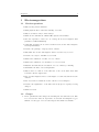
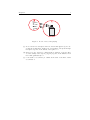
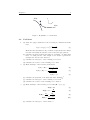
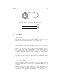
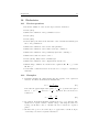
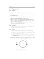
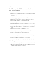
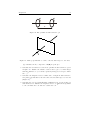
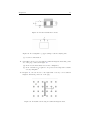
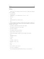
Review questions, examples, grasps and problems for Electromagnetic Field Theory Miko Elwenspoek, Leon Abelmann, Wouter Olthuis, Remco Wiegerink, Theo Lammerink April 19, 2011 In this document you will find material to help you practise Electo- and Magneto-statics. The Feynman lecture notes on physics are perfect for the type of course we’d like to give, but they are what they are: edited manuscripts of seminars. Therefore they complete lack a set of problems which you will find in modern study-books. So instead, like Feynmans assistents 50 years ago, we have created a set of problems for you. There are four different types of problems you will find in this document Review These are questions which are answered literally in the Feynman Lecture notes. If you read the text well, you can answer them. Alternatively, you can use the questions to go through the text. Example Feynman gave many examples in his lectures, but they are not indicated as such in the book. We have pointed them out for you. If there were no clear examples (like in chapter 1 and 2), we made one for you. We will not provide other examples here, because we know from experience that you will forget to read the book. Grasp The way we like to teach EM-field is not by making you suffer throught the mathematics, but rather trying to make you understand the nature of electric and magnetic fields. We want you to grasp the essence. The grasp questions are designed for that: no -or minor- calculation but maximum understanding.1 Problem Of course you also have to calculate fields. We keep the problems simple though, more difficult geometries than plates, lines, cilinders and spheres will not be treated. 1 Some of the grasp questions a taken from the book “Peer Instruction: A User’s Manual” by Eric Mazur (Prentice Hall, 1997). 1 Chapter 1 1 2 Electromagnetism 1.1 Review questions • Why are large nuclei unstable? • What physical effect causes the stability of atoms? • Why does matter carry so little charge? • What are the dimensions of E and B, expressed in SI units? • Give the expression of the force on a charge in an electromagnetic field (definition of E and B fields) • Using this expression, how can we tell there is an electric and a magnteic field experimentally? • Describe the principle of superposition of fields • Why must the electric and magnetic field be described by vectors? • Describe two ways to visualize vector fields • What is the definition of a flux of a vector field? • What is the definition of a circulation of a vector field? • Illustrate the flux and the circulation of a vector field by a drawing • Summarize the laws of electromagnetism • Why is there a relation of the flux law of the electrostatic field with Coulomb’s inverse square law? • How acts the magnetic field of a bar magnet on a wire fed with an electric current? • How acts a wire fed with an electric current on a bar magnet? • Describe the significance of the first term in (1.9) if a capacity is being charged • What is a field? 1.2 Grasps 1. In two parallel wires the charges are traveling into the same direction. The force between the wires is dependent on electrical and magnetic forces. Which of both types of forces is the largest and which is dominant? 1 Chapter 1 3 Figure 1: Balloons on the MIT Courseware site 1.3 Problems 1. Calculate the force of two charges of 1[As] (=1[C]) at a distance of 1 [m]. Compare this force to your bodyweight. 2. If in a good isolator the electric field exceeds 108 [V/m] there will be a voltage breakdown, the material becomes conductive. Calculate the force on an electron in a field of this strength. 3. The magnetic field close to a straight wire is given by B= I 0 c2 2πr the field is directed tangential to circles concentric to the wire. What is the unit of B? Calculate B at a distance of 0.01 [m] from the wire with a current of 5 [A]. Calculate the force on an electron travelling parallel to the wire with a speed of 0.01 [m/s]. (Note the drift velocity of electrons in good conductors is of the order of 0.01 [m/s]!) 4. On the MIT Courseware site, you can see an experiment with balloons (Figure 1) (MIT OpenCourseWare -Electrical Engineering and Computer Science - Electromagnetics and Applications, Fall 2005, Video lectures Coulomb’s Force Law and Measurements of Charge) The professor in the movie measures the charge on the balloons. We can also estimate the charge from the distance between both balloons. The gravity will pull both balloons together, the electrostatic forces will pull them apart and in rest both forces will cancel. Assuming a certain weight, you can calculate the charge. Does that agree with the measurement of professor? 5. The velocity of particles v of a liquid flowing through pipe with radius R varies as v = v0 (1 − (r/R)2 ) between r = 0 and r = R, with ry = 0 and r = |r| [m], v = |v| [m/s], and the center of the pipe at r = 0 [m]. Chapter 1 4 z x y Figure 2: Round tube with a parabolic flow-velocity profile inside (a) make a sketch of v(r). (b) make a three-dimensional sketch of v. (c) include in a different colour the vectors r starting from a suitable reference point of the points in the tube where you have drawn the vectors v. (d) replace the vectors description by field lines 6. For the configuration of Problem 5 (see Figure 2), consider the flux of v. Start with a circular surface with a radius a in the x − z plane and centered around the y-axis. (a) How will the flux depend on the radius (qualitively)? 2 (b) What will change if the normal of the surface makes an angle φ with the axis of the tube, while leaving the size of the surface constant? 3 (c) How do you have to change the surface (qualitatively) to keep the flux the same if the angle varies? 4 (d) What is the flux of v through all side-wall of a cylinder of radius a concentric with the axis of the tube with its ends at -l and at +l (so total length of 2l)? 5 (e) Consider now a closed surface in the tube (cilinder side-wall + two end-faces). What can you say about the flux through such a surface in this particular case? 6 7. For the tube-configuration of Problem 5 (see Figure 2), consider the circulation of v around curves. (a) The circulation of v around the circles of problem 5. 7 (b) The circulation around squares in the z − y plane means that the square is on the tube-axis. How does the circulation depend on the position of the square on the tube’s axis (see Figure 2)? 8 8. Consider an aersol spray, emitting a number N [-] of small droplets of mass m [kg] per second of some liquid at a certain velocity v [m/s] (see Figure 3). (a) Consider a closed surface (e.g. sphere) around the nozzle (sphere-1 in the figure). How does the flux of droplets through the sphere depend on the radius of the sphere? 9 (b) What is the unit of this flux?10 Chapter 1 5 2 1 Figure 3: A can of aerosol is spraying (c) Now consider a closed sphere in front of the nozzle (sphere-2), not enclosing the nozzle itself. Again, how does the flux of droplets through the sphere depend on the radius of the sphere? 11 (d) If I don’t look to well, I see continuous flow of matter, a vapour. How does the density of the vapour ρ [kg/m3 ] depend on the distance from the nozzle qualitatively? 12 (e) I can define a vectorfield ρv. What is the unit of the flux of this vectorfield? 13 Chapter 2 2 6 Differential Calculus of Vector Fields 2.1 Review questions • What is a scalar field (in words and by equations) • What is a vector field (in words and by equations) • Give examples for both types of fields • What is the definition of the gradient? • How is the direction of heat flow related to increase or decrease of T in space? • What is the precise mathematical definition of heat flow • What is the heat flow through a surface • Why is ∂T /∂x neither a scalar nor a vector? • What is the difference between ∇T and T ∇ ? • What is the definition of the divergence • What is the definition of the rotation • Which second field derivatives are zero? • Under what conditions exists a scalar field Ψ such that∇Ψ = H? • Under what conditions exists a vector field A such that ∇ × A = H? • What is the Laplace operator? Is it a vector or a scalar? 2.2 Example 1. (a) Make drawings of the following two-dimensional vector field: B(r) = xey − yex (x2 + y 2 )n (1) Answer: The first thing you should note is the vector notation using the unity vector e, which has components (ex , ey ). So we can also write (1) as: −y x , (2) B(x, y) = (Bx , By ) = (x2 + y 2 )n (x2 + y 2 )n Obviously, we get different graphs for different values of n, see figure 414 .pThe case for n = 0.5 is special. The denominator in that case is (x2 + y 2 ), which is the length of the vector (x, y). So the vector length is 1 everywhere. Chapter 2 7 1 1 1 0.5 0.5 y0 y0 –0.5 –0.5 –1 0.5 y0 –0.5 –1 –1 –1 –0.5 0 x 0.5 1 –1 –0.5 0 x 0.5 1 –1 –0.5 0 x 0.5 1 Figure 4: Field for n = 0.1, n = 0.5 and n = 1 (b) Calculate the divergence of this field. Is there an n for which ∇ · B = 0? Answer: For the divergence we have to calculate ∇·B = So let’s start with ∂By ∂Bx + ∂x ∂y ∂Bx ∂x ∂ ∂Bx = ∂x ∂x −y −y 2 (x + y 2 )n ) = ∂ 2 (x + y 2 )−n = −y · −n(x2 + y 2 )−n−1 · 2x = ∂x 2nxy (x2 + y 2 )n+1 Similarly, we get for x ∂By ∂y ∂ 2 (x + y 2 )−n = x · −n(x2 + y 2 )−n−1 · 2y = ∂y −2nxy (x2 + y 2 )n+1 The sum is zero! Hi, hi, the divergence is zero everywhere... (c) Calculate the rotation of the field. What is the direction of the rotation of field (1)? Is there an n for which ∇ × B = 0? Answer: The rotation of the field is a vector: ∂By ∂Bz ∂y − ∂z ∂Bz x rotB = ∇ × B = ∂B ∂z − ∂x ∂By ∂Bx ∂x − ∂y Since this is a twodimensional field in the (x, y) plane, both Bz and the partial derivatives to z are zero. So the rotation will only have a z component. Just like above we have to calculate two derivatives. ∇×B = ∂Bx ∂By − ∂x ∂y ez = Chapter 2 8 Starting with the first one, using the chain rule (or the quotient rule, if you can remember that) we get ∂By ∂ = ∂x ∂x x 2 (x + y 2 )n = 1 · (x2 + y 2 )−n + x · −n(x2 + y 2 )−n−1 · 2x = (x2 + y 2 ) − 2nx2 (x2 + y 2 )n+1 Similarly, we get for −(x2 + y 2 ) + 2ny 2 ∂Bx = ∂y (x2 + y 2 )n+1 And subtraction yields ∇×B = 2(x2 + y 2 ) − 2n(x2 + y 2 ) 2(n − 1) = 2 (x2 + y 2 )n+1 (x + y 2 )n So for n = 1 ∇ × B equals zero everywhere. This is when the vector p length drops off with 1/R, with R = x2 + y 2 . Note however that this is only true outside the origin (0, 0). The direction of ∇ × (B) is in the positive z-axis for n < 1, and in the negative direction for n > 1. You can check that intuitively in figure 4. Put a wheel anywhere in the graph, outside the origin. The wheel will turn counterclockwise for sure for n = 0.1 and n = 0.5. For n = 1 the wheel won’t turn, you’ve just seen the calculation! But for n > 1 the drop off is more rapid, and the wheel will start turning clockwise. 2.3 Grasps 1. Write out the components of ∇ · E and ∇ × E. 2. What is the unit of the gradient, divergence and the rotation operator. 15 3. Sketch the gradient of the scalar field (a height) given in figure 5. Show the x- and y-components of the gradients, too. 4. Indicate of the following operations whether they are a valid, and if so, whether the result is a vector or a scalar field. V is a scalar field, A is a vector field. (a) rot(rot(A))) (b) grad(grad(V)) (c) div(div(A)) (d) div(grad(V)) (e) grad(div(A)) Chapter 2 9 20 m y x 10 m Figure 5: Heightlines of a scalar field 2.4 Problems 1. (a) Draw the equipotential lines of the following two-dimensional scalar field p V (r) = ln(|r|) = ln x2 + y 2 (3) Make sure that the difference in potential for adjacent lines are always the same and adjust the distance between the line appropriately. (b) Calculate the field gradient and make two drawings, one using field lines, one using arrows. The length of the arrows represent the strength, the direction the direction. (c) Calculate the divergence of the resulting vector field. (d) Calculate the rotation of the resulting vector field. 2. (a) Make drawings of the following scalar fields: p V (R) = |R| = x2 + y 2 + z 2 1 V (R) = |R|−1 = p 2 x + y2 + z2 V (R) = xy (4) (5) (6) (b) Calculate the gradients of the fields and make drawings (c) Calculate the divergence of the resulting vector fields. (d) Calculate the rotation of the resulting vector fields 16 17 18 3. (a) Make drawings of the following vector fields (R = (x, y, z)): A(R) = R R A(R) = eR = |R| eR R A(R) = = |R|n |R|n+1 xey − yex A(R) = 2 (x + y 2 )n (b) Calculate the divergence of these fields. 19 (7) (8) (9) (10) Chapter 2 10 (c) Calculate the rotation of the fields. If the rotation is non-zero, what is the direction of the rotation. 20 (d) For 9, is there an n for which ∇ · A = 0 ? 21 (e) For 10, is there an n for which ∇ × A = 0? 22 4. Consider vector fields oriented along the x-direction. 1 allow for one field that the strength of the field increases proportional to x in x-direction but constant in y- and z-direction 2 allow for another field that the strength of the field increases proportional to y in y-direction but constant in x- and z-direction (a) make drawings of these fields (b) give a mathematical description of the fields (c) calculate divergence and rotation of the fields Chapter 3 3 11 Vector Integral Calculus 3.1 Review Questions • What is the relation between gradient and line integral? • What is the definition of a flux? What is the sign convention for the flux through a closed surface? • What is the definition of the circulation? What is the sign convention? • What is the relation of the divergence and the closed flux integral (Gauss’ theorem)? Illustrate the theorem by a drawing, which shows the field, the relevant volumes and surfaces. • What is the relation of the rotation and the closed line integral - the circulation (Stokes’ theorem)? • Illustrate the theorem by a drawing, which shows the field, the relevant lines and surfaces. • Formulate the line integral as a sum, and illustrate the sum by a drawing. • Formulate the flux integral as a sum, and illustrate the sum by a drawing. • What is the description of a conservation law in integral form? • What is the description of a conservation law in differential form? • What is the condition to describe a vector field by a gradient of a scalar field? • What is the condition to describe a vector field by a rotation of a vector field? • What is the definition of the divergence expressed by an integral • What is the definition of the rotation expressed by an integral. 3.2 Example 1. Consider the following vector field: −y A= x 0 (11) (a) Is the line integral independent on the path? Answer: When the line integral is independent on the path, this means that we have a conservative field, so ∇ × A = 0. ∂Ay ∂Az ∂y − ∂z ∂Az x rotA = ∇ × A = ∂A ∂z − ∂x ∂Ay ∂Ax ∂x − ∂y Chapter 3 12 ∂ are zero. The only This is a two-dimensional field, so Az and ∂z ∂Ay ∂Ax terms to condider are ∂x = 1 and ∂y = −1. So ∇ × A = (0, 0, 2), so for this field the line-integral is not independent on the path. Of course, it is a rotating field: take a circle around the origin and you will see that walking around the path clockwise or counterclockwise makes a difference. (b) Calculate the line integrals for the paths in figure 7. Answer: On a circle with its center in the origin and radius R, the p field A has a constant length x2 + y 2 = R. When we walk counterclockwise along the path, the direction of the field is exactly along the path. So Z Z Z Adl = Rdl = R dl = 2πR2 If the path is defined clockwise, the sign reverses. In the right figure, we can identify four pieces in the path. There are two semicircles, let’s define the outer one with radius R1 and the inner one with R2 , and two straight pieces connecting the semi-circles. These straight parts are trivial: the field A is always perpendicular to those parts, so the contribution of the line-integral is zero. Walking counterclockwise along the outer circle, dl has the same direction as A so the line integral increases to πR12 , the straight part does not contribute , the inner circle subtracts πR22 and again the straight part doesn’t add. In total the line integral for counterclockwise integration is π(R12 −R22 ). Note that if R1 = R2 , the integral vanishes. And when R2 = 0, we get exactly half the value calculated for the full circle. Figure 6: Solution 3.3 Grasps 1. What is the physical meaning of the volume integral of the divergence of a ’heat vector field’ h over a volume V ? 2. In Stokes theorem there is no statement on the form of the surface through which the flux is evaluated. Why? 3. Check the units of the theorems of Stokes and Gauss. 23 Chapter 3 13 y y x x Figure 7: Line integral paths 4. Draw pictures to illustrate the integrals versions of the gradient, rotation and divergence operations. Indicate all symbols used. Z (2) φ(2) − φ(1) = ∇φ · ds (1) I Z C · ds = (∇ × C)n da S IΓ Z C · n da = ∇ · C dV S 3.4 V Problems 1. Prove that a flux of a conserved quantity emerging from a point source varies as 1/R2 in three dimensions. Hint: start by assuming a velocity v = 1/Rn eR . 24 2. Show that a flux of a conserved quantity emerging from a point source varies as 1/R in two dimensions. 3. Consider vector fields oriented along the x-direction. 1 allow for one field that the strength of the field increases proportional to x in x-direction but constant in y- and z-direction 2 allow for another field that the strength of the field increases proportional to y in y-direction but constant in x- and z-direction. (a) For which field is the line integral independent on the path? 25 (b) Verify the theorems of Gauss and Stokes for these fields 4. Consider the following vector fields: −y 1 x A1 = 2 R 0 x A3 = y z x 1 y A4 = 3 R z p R = x2 + y 2 + z 2 (12) (13) (14) Chapter 3 14 (a) For which field is the line integral independent on the path? (b) Calculate the line integrals for the paths in figure 7. 27 26 Chapter 4 4 15 Electrostatics 4.1 Review questions • What is the unit of the electric field E? • Which equations describe electrostatic problems? • Which terms in eq. (4.1)-(4.4) describe the coupling between electric and magnetic fields? • Why is in eq. (4.17) the distance in the denominator to the third power, while it is to the second power in eq. (4-9)? • Formulate Couloms law, using vectors • Give an expression for the electrostatic field at an abitrary point in space for a pointcharge at R = R0 . • Give an expression for the electrostatic field for a charge distribution using vectornotation. • Give an explanation of why the flux of an electrostatic field through any closed surface is zero if there is no charge in the volume. • What is the definition of the electrostatic potential. Why is the definition not sound if the electromagnetic field is time dependent? • Give the formula for the electrostatic potential of a point charge and a charge distribution. • State Gauss’ law. • Review the convention of representing a field by field lines and by arrows. • What is the direction of a field made by a negative charge? • What can be said on the relation of equipotential surfaces and electrostatic fields? 4.2 Example 1. In Section 4-7, page 4-10, Feynman applies Gauss’ law to calculate the electric field of a sphere of charge. Note that you can use the same derivation for any spherical-symmetric charge distribution. 4.3 Grasps 1. If the electrostatic potential at a point P is zero, does it follow that the electric field is also zero at P ? 2. If the electric field at a point P is zero, does it follow that the electrostatic potential is also zero at P ? 3. A current consists of moving charges. How can it be that we can consider this as a stationary situation? Chapter 4 16 10 5 0 Figure 8: Equipotential lines 4. Consider Coulomb’s law (eqn. 4.9). Make a drawing of the two charges and the forces acting on them, for four situations: (q1 > 0, q2 > 0), (q1 < 0, q2 > 0), (q1 > 0, q2 < 0) and (q1 < 0, q2 < 0). Also draw e12 . Is F 1 the force acting on q1 or q2 ? 5. Consider 3 charges with charge q at the following positions: (1,0,0), (1,0,0) and (0,1,0). What is the size and direction of the electric field E(0, 0, 0) in the origin? Make a drawing of this situation and E(0, 0, 0). 6. Consider an infinitely large uniformly charged plate in the yz plane at x = 0. The charge density is ρ [coulomb/meter2 ]. Derive an expression for the electric field E(x, y, z). Calculate the work needed to move a charge q in this field from (1,0,0) to (4,8,5). What is the electrostatic potential difference between these points? 7. Draw the size of the electric field and potential as a function of the distance r from a point charge q. 8. Between two points in space there is a potential difference of 1000V. What is the work required to move an electron from one point to the other? Does the electron move by it self from the larger value of φ to the smaller or the other way around? 9. At some point in space there is a potential of 10V. What can you say, if anything on the electrostatic field in this point? 4.4 Problems 1. Use the theorems of Gauss and Stokes to formulate the Maxwell equations (4.1)-(4.4)in integral form 2. At the points (1,0,0) and (0,1,0) there are two charges with charge -1 As and +2 As, respectively (1 As=C). (a) Calculate the electric field at (0,0,0) (b) Calculate the x-component of the electric field at (5,5,0) (c) Sketch the field lines and field vecors of the field in the z = 0 plane 3. Show that ∇×E = 0 , with E taken from (4.17). Note: Does the operator (∇×) act on position 1 or on 2? 4. Draw electric field vector in the points given in figure 8. Where is the region with the maximum field. 28 Chapter 4 17 Figure 9: Flux through two surfaces 5. Show that for any radial force field F (R) = F (|R|) = F (R), that the circulation along any path equals zero. Hint: write the field as F (R) = RΨ(|R|). Does this fit with Stokes’ theorem? 29 6. Show that the flux of a homogeneous field through a cube equals zero (choose one length of the cube along the direction of the field) 7. Show that the flux through the two surfaces shown in figure 9 is the same for a homogeneous field. 8. Consider a field F (R) = R |R|3+ Calculate the flux through a spherical surface centred at R = 0 of two different radii. These two concentric spheres form a closed surface excluding the point R = 0. What is the flux through this surface? How does the flux depends on ? How does this fit with Gauss’ theorem? What would you conclude on the charge distribution if F were an electrostatic field? Chapter 5 5 18 Application of Gauss’ law 5.1 Review questions • Why is in the centre of a triangle with equal charges at the corners the field zero? • Why then is there no minimum of φ? • Why cannot exist a minimum of φ where there are no charges? • How can you fix charges in a stable position? • What is the reason for the stability of atoms? • Why is it impossible to fix a charge in a stable position in the centre of a charged sphere? • Derive eq. (5.2), (5.3) and (5.7) • What would be the field between the plates in fig. 5-7 if both plates were positively charged? • Describe the relation of Gauss’ law and Coulomb’s force law • Why is the field inside a sphere with homogeneous surface charge zero? Repeat two arguments • Derive eq. (5.8) • Explain the difference between the fields of a plane homogeneously charged sheet and at the surface of a conductor • Explain why there is no field in a cavity inside a conductor • Do the conclusion of fields inside and at the surface of a conductor also apply for poor conductors such as water? • Review the precision of the exponent two in Coulomb’s force law and the range of validity of the prefactor • Consider Feynman’s remark on shielding: (second last paragraph on p. 5-9). Surround a pointcharge with a spherical shell of metal. Is the field outside zero? Gauss’ law tells us it is not. What do we forget? • Place a charge inside a potato-shaped cavity of a conductor. What can you say on the electrostatic field at the inner surface? Where is the stable position of the charge? Chapter 5 19 0V 5V Figure 10: Potential distribution 5.2 Examples 1. In Section 5-5, page 5-3, Feynman applies Gauss’ law to a cylindrical symmetric configuration to find the electric field of a line of charge. Note that the result is valid for any cylindrical charge distribution, so also for a uniformly charged cylinder and a hollow cylinder. 2. Feynman uses Gauss’ law to find the electric field between two sheets of charge. Note that this configuration is similar to a parallel plate capacitor if the sheets are charged conductors. You can integrate the electric field to find the voltage between the sheets (multiply the electric field by the distance between the sheets) and you can find the total charge by integrating the charge density over the area of the sheets (multiply the charge density by the area). The capacitance is defined as the ratio between the charge and voltage. The result is the well-known expression for a parallel plate capacitor. 3. In Section 5-7, page 5-4, Feynman applies Gauss’ law again to a spherical symmetric configuration, but now he calculates the field inside the charge distribution (compare to Section 4-7). 5.3 Grasps 1. Is Gauss’s law useful for finding the E field of a finite line charge? 2. A positively charged sphere is hanging from a very long rope between two uniformly charged plates. Can this be a stable equilibrium? That is, if the sphere moves slightly towards one of the plates, will it return to it’s original position? Does it matter whether the plates are charged positively or negatively? 3. A conducting sphere is brought into a uniform electric field. Make a drawing of the electric field and the charge distribution in the sphere. Does anything change when the sphere is hollow? 30 4. Is the potential distribution given in figure 10 possible? Why (not)? 5. Given the impossibility of static equilibrium of a charge distribution, how is it possible that we can hold charged capacitor plates on a distance? Chapter 5 20 a2 a1 Figure 11: Homogeneously charged hollow cylinder -Q +2Q -Q Figure 12: Three infinitely large parallel plates 5.4 Problems 1. Calculate the electrostatic field inside an infinitely long homogeneously charged cylinder. 2. Calculate the electrostatic field inside an infinitely long homogeneously charged cylinder with a central hollow bore (see figure 11). 31 3. Use Gauss’ theorem to find the electrostatic field of three infinitely large plates with surface charge density as shown in figure 12 below, in the space between the plates and outside. 4. Consider two concentric conductive spherical shells with inner radius a1 and a2 , respectively, both with thickness t. On the smaller one there is a charge Q, on the larger one there is the charge −Q. Calculate the electrostatic field using Gauss’ theorem everywhere. 32 Find the surface charge density on the four surfaces of the shells. 33 5. Consider the same configuration as in the previous problem, but now the larger shell is charged with −2Q. Find again the fields and the charge densities. 6. Find in both problems above the electrostatic potential, taking the reference of φ = 0 at infinity. 7. For the configuration of the problem above find the electrostatic potential everywhere. Why is it impossible to set φ = 0 at infinity? What is a good alternative? 8. Consider a ring in the xy plane with its centre in the origin (Figure 13). The ring has radius a and is charged with a charge density λ [C/m]. Calculate the electric field E in a point P (0, 0, z1 ) on the z-axis. 34 Chapter 5 21 Figure 13: Charged ring 9. Consider a ring in the xy plane with its centre in the origin (Figure 13). The ring has radius a and is charged with a charge density λ [C/m]. Calculate the electric field E in a point P (0, 0, z1 ) on the z-axis. Chapter 6 6 22 The Electric Field in Various Circumstances 6.1 Review questions • What is Poison’s equation? • What is its general ‘solution’ ? • Formulate Poisson’s equation for the case that the potential depends only on x. • Give the potential and the electric field of a dipol. • Describe the method of images. Why does this method works only for conductive materials? • What is the force between a point charge and a conducting plate? • Describe the phenomenon of charge breakdown. Why are flashes caught by metal tips? • Recall the definition of the orientation of the dipole and compare this to the field acting between the charges. 6.2 Examples 1. In section 6-2, pages 6-2 and 6-3, Feynman calculates the potential and electric field of an electric dipole starting from equation (4.24), which gives the potential resulting from a number of discrete charges. 2. In Section 6-10, page 6-12, Feynman calculates the capacitance of a parallel plate capacitor, which we already found in example 5.2. 6.3 Grasps 1. When a voltage source is connected across a capacitor, what is the direction of the electrical force acting on its conducting surfaces? 2. A point charge is positioned close to an infinitely large conducting plate. Describe the charge distribution in the plate. Will there be an electric field at the other side of the plate? Is there a force acting on the point charge? 35 6.4 Problems 1. Find the electrostatic field and the surface charge densities of an infinitely long coaxial cable, which consists of a solid inner core (radius a1 ) and an outer metallic coating with inner radius a2 and thickness t. Assume (a) a charge Q per length of opposite sign on core and coating, (b) twice the charge per length on the core. 36 37 In both cases the charge on the core is negative. Don’t mind the dielectric between core and coating. Chapter 6 23 2. Derive Poisson’s equation 3. For a certain temperature distribution we have the following differential equation: ∇2 T = κh(R) κ is the heatdiffusion constant, h(R) is a distributed heatsource. Give the solution for T (R) in terms of an integral. 4. Expand the following equation up to terms of the order 3 in d. 1 p x2 + y2 + (z − d/2)2 5. Derive (6.14) starting from the electric fields of the two charges located at (0, 0, +d/2) and (0, 0, −d/2). 6. Starting from (6.13), derive the potential of two closely spaced antiparallel dipols, following a procedure analogous to find (6.13) from (6.8) 7. Correct the expression for a parallel plate capacitance (6.34) according to the recipe given in the paragraph following this equation. Assume square capacitor plates so that A = a2 . Find the condition that the amount of the correction to (6.34) is below 1%. 8. Starting from φ(R) = 1 4π0 Z ρ(R0 ) dV 0 |R − R0 | show that the first two terms in a series expansion of is given by 1 1 φ(R) = 4π0 R Z 1 R ρ(R )dV + 4π0 R3 0 0 Z 1 |R−R0 | for |R0 | |R| ρ(R0 )R0 dV 0 9. In an H2 O molecule assume the distance between charges of ±1.6·10−19 As is 0.5 Å(= 5 · 10−10 m). Direct the axis of the dipole along the z-axis of a coordinate system. Calculate the electrostatic potential at a distance of 5 Åalong a circle in the zx- plane. Find the location of the maximum force on a proton. What is its magnitude? Chapter 8 8 24 Electrostatic Energy 8.1 Review questions • Review the argumentation that leads to (8.3) • Why is there a minus sign in the definition of the electrostatic potential? (9.1) is positive if both charges have the same sign. What does this mean in terms of work? • (9.1) is negative if the charges gave opposite sign. (8.35) is always positive. What is the difference in these expressions? • What is the energy of a capacity with a charge Q? • What is the force between two oppositely charged capacitor plates? • What is the significance of the minus sign in equation (8.15) • Express the energy density in regions with an electric field in terms of E. 8.2 Examples 1. In equation (8.11) Feynman combines expression for the energy stored in a capacitor and the previously calculated capacitance of a charged sphere to find the energy of the charged sphere. 8.3 Grasps 1. Which system has the highest energy: two point charges +q1 and +q2 at distance d, or charges −q1 and −q2 at the same distance? 2. Give an expression for the total electrostatic energy of a system of 3 point charges q1 , q2 and q3 . 8.4 Problems 1. Express the capacity in terms of an integral over the electric field (hint: use (8.35). 2. Using this result, derive the capacity of a parallel plate capacitor. 3. Find for the configuration of problem 6.4.1(a) the capacity per length using (8.35) and (8.9) 38 4. Using (8.35), derive the work needed to charge a metallic sphere of radius a. 5. Find the pressure between the shells in problem 5.4.4. 39 Chapter 10 10 10.1 25 Dielectrics Review questions • Recall the definition of the electric dipole and its orientation. • Derive (10.3). • What is the definition of the polarization vector? • Derive (10.5) • Derive (10.6) • Is E in (10.6) the field in the material or the external field which gives rise to the polarization? • What is the definition of the electric susceptibility? • What is the definition of the relative dielectric constant κ? • What is the definition of the permitivity (dielectric constant) ? • What is the relation between and c? • Derive (10.16). Why is there a minus sign? • What is the definition of the ”displacement current” D? • Which charge densities are meant in the equations ∇ · E = ρ/0 and ∇ · D = ρ? • Under what conditions is there an electric force on a piece of uncharged material? 10.2 Examples 1. Feynman calculates in equations 10.1-10.3 the capacity of two capacitors in series. You know from Network Analysis that Ctot = 1 1/C1 + 1/C2 (15) If we take the gaps in figure 10-2 equal to δ = 12 (d − b), than each capitor has C1 = C2 = 0δA , and Ctot = 21 C1 . Equation 10.3 can indeed be rewritten to C= 0 A 0 A = d−b 2δ (16) 2. In equation 10.30-10.32 Feyman calculates the force on a dielectric slab inserted in a capacitor under constant voltage. Following the same reasoning, you should be able to calculate the force between two capacitor plates. 3. We hebben nog een voorbeeld nodig voor opgave 10.4.3. van E, P, D phi overal. Bijvoorbeeld in een plaatcondensator? Chapter 10 10.3 26 Grasps 1. Compared with the applied electric field, the electric field within a linear dielectric is (a) smaller (b) larger (c) depends on the dielectric 2. Suppose that the conducting plate in the capacitor of figure 10-2 fills 99% of the room between the plates (b = 0.99 d). Would this filling result in a relative high or low capacitance, compared with filling with mica with r = 5.5? 3. Suppose in Fig. 10-9 in the Feynman book on page 10-9, we replace the dielectric by a conductor. What would happen to the force: increase, decrease, become zero, reverse in sign?40 4. What would be the susceptibility and relative dielectric constant of a metal conductor? 5. A dielectric is inserted between the plates of a capacitor. The system is then charged, the wires are disconnected, and the dielectric is removed. The electrostatic energy stored in the capacitor is (a) greater than (b) the same as (c) smaller than it would have been if the dielectric were left in place.41 6. A parallel-plate capacitor is attached to a battery that maintains a constant potential difference V between the plates. While the battery is still connected, a glass slab is inserted so as to just fill the space between the plates.The stored energy 42 (a) increases (b) decreases (c) remains the same 7. In order to increase the energy stored in a parallel-plate capacitor when an electric potential is applied, we should (a) increase the area of the plates (b) increase the separation between the plates (c) insert a dielectric between the plates (multiple answers are possible) 8. A conducting sphere of radius a carrying a charge q is submerged halfway into a non-conducting dielectric liquid of dielectric constant κ. The other half is in air. Sketch the dielectric displacement D, polarisation P and electric field E. Chapter 10 10.4 27 Problems 1. Reverse the definition of the sign for the electric dipole. What are the consequences for equations (10.13), (10.16), (10-21) and (10.24) (pages 10-5 and 10-6)?43 2. Equation 10.22 formulates the Maxwell equations for electrostatics in differential form in terms of E and D . Reformulate these equations in integral form. 3. A point charge is surrounded by a dielectric spherical shell with permitivity , inner radius a and thickness b. Find E, P , D and φ everywhere in space. Make a graph of E, P , D and φ as a function of R. 4. Find the polarization charge density of 10.4.3 on either surface of the shell. 5. Work out an expression for ∇ × D. What are the conditions for ∇ × D = 0? 6. The space between two concentric spherical shells of radii b and a (where b < a) is filled with a substance of dielectric constant κ. On the inner shelll there is a charge Q. On the outher shell there is a charge −Q. • Find E,P ,D and φ everywhere in space.44 • Determine the capacitance of the device.45 7. The dielectric of a parallel plate capacitor has a permittivity that varies as 1 + ax, where x is the distance from one plate. The area of a plate is A and their spacing is s. • Find the capacitance. 46 • Assume 1 + ax varies from 1 to 21 . Find P from D and E for that case.47 • Find the polarization charge density ρp 48 8. Suppose we construct two parallel plate capacitors as shown in figure 14. Each capacitor has plate area A and plate separation d. We place two dielectric materials between the plates, with dielectric constants κ1 and κ2 . Calculate the capacitance of these two configurations. If κ1 < κ2 then which of these two configurations gives the largest capacitance? What are the values of E,D and P in both cases. Make a drawing of these vectorfields. 9. Consider the interface between two dielectric materials, see figure 15. The electric field in material 1 has direction θ1 with respect to the interface and strength E1 . Calculate the strength E2 and direction θ2 of the electric field in material 2. Chapter 11 28 Figure 14: Capacitor with two different dielectircs Figure 15: Interface between two dielectrics 10.5 Reading 1. Read chapter 7-3 (plasma oscillations), page 7-5 to 7-7. (a) Explain the difference between ∆x and ∆s in the derivation of equation (7.16). (b) Illustrate with a calculation why Copper is not transparent. In Copper there is about 1 electron per cubic [Å] (1Å = 10−10 [m]), the angular frequency of visible light is ω = c/λ, with λ between 4000 and 7000 [Å], c = 300000 [km/s], 0 = 10−11 [Vs/Am], the elektron mass is 10−30 [kg]. (c) Explain why an electric field with a frequency below the plasma frequency cannot penetrate the plasma. Chapter 12 12 12.1 29 Electrostatic Analogons Review • Derive an expression for the current density in terms of the velocity of charges • Derive the force between two straight parallel wires carrying a current • Derive Ampere’s law • What is the magnetic field B of a straight wire? • What is the magnetic field B inside a long solenoid? • Two electrons move in Tim’s reference system in parallel with a speed v. Is there a magnetic field? Tom, moving also with the speed v, says: no there is no magnetic field. Explain. • Review the complete Maxwell equations. Where may be sources of confusion between Tim’s and Tom’s viewpoint? Chapter 13 13 13.1 30 Magnetostatics Review • Derive an expression for the current density in terms of the velocity of charges • Derive the force between two straight parallel wires carrying a current • Derive Ampere’s law • What is the magnetic field B of a straight wire? • What is the magnetic field B inside a long solenoid? • Two electrons move in Tim’s reference system in parallel with a speed v. Is there a magnetic field? Tom, moving also with the speed v, says: no there is no magnetic field. Explain. • Review the complete Maxwell equations. Where may be sources of confusion between Tim’s and Tom’s viewpoint? 13.2 Example 1. Feynman calculates the field around a straight wire, and inside a solenoid using Ampère’s law on page 13-5 and 13-6. 13.3 Grasps 1. Consider a circular loop in a external homogeneous field (Figure 16). (a) Draw the force on the loop caused by the external field only49 . Wat happens if the field is reversed50 ? (b) Consider the field caused by the above current loop only. Draw the field and the force excerted by it on the loop51 . What happens if the current is reversed52 . 2. Kirchhofs law states that the sum of the currents going into a node equals zero (see figure 17). How does this follow from ∇j = −∂ρ/∂t. Bext I Figure 16: A current carrying loop Chapter 13 31 I1 I2 I4 I3 I1=I2+I3+I4 Figure 17: Kirchhof law + + + + + + + + + + + v v + + + + + + + + + + + v Figure 18: Two charged wires 3. Consider two charged parallel wires (figure 18). What is the direction of the forces (electric and magnetic) on the wires, when they both move at speed v, parallel to their axis53 . Same question, but now for an observer moving at the same speed as the wires54 ? 4. Ampere’s law (equ. 13.16) can be used to determine B from currents with certain symmetries. Is Ampere’s law suitable for computation of B in the centre (point P ) of a square current-carrying loop? 5. Is there a net force acting on the wires of a long solenoid carrying a current I as in Fig. 13-8? 13.4 Problems 1. Use Ampere’s law to calculate the magnetic field inside a straight wire with current density j 55 2. Use Ampere’s law to calculate the magnetic field inside a straight wire with a central bore of diameter a with current density j (see figure 19)56 . 3. When deriving (13.17), it is assumed that the magnetic field is parallel to concentric circles normal to the wire. Why are magnetic fields normal to the wire or parallel to the wire excluded? 4. When deriving (13.19), it is assumed that the magnetic field is parallel to the axis of the solenoid. Why are magnetic fields normal to the axis or parallel to the wire excluded? Chapter 13 32 a2 a1 Figure 19: Current carrying wire with a central hollow bore 5. Consider a large plate with thickness d carrying a homogeneous current density parallel to the surface, so that the total current through the plate is I. Determine the magnetic field on on either side of the plate close to the surface. How does it vary on the distance z from the plate (assuming z small compared to size of the plate). 13.5 Reading 1. Read in Feynman paragraph 7-4 about colloidal solutions on pages 7-8 to 7-10. Calculate the charge density as a function of x, ρ(x), if there is on the average 1 part per (10 nm)3 in the solution (n0 = 10−24 m−3 ). Assume room temperature (T = 300K) and an electron charge of qe = 1.6·10−19 C. Chapter 14 14 14.1 33 The magnetic field in various situations Review questions • Recall the definition of B • What is neglected of the Maxwell equations to find eq. (14.1) and (14.2)? • Why is the divergence of B always zero with the choice of A according to eq. (14.3)? • Why can we add to A any constant vector or any gradient of a scalar field without changing the physics? • What exactly is meant with the phrase ”the physics is not changed”? • Review how A looks like for a constant magnetic field. • Derive eq. (14.10) • Check that the divergence of A is zero for all choices of A in eq. (14.8) • Derive eq. (14.19). Review the meaning of 1 and 2 in eq.’s (14.18), (14.19). • Describe the analogy of (14.19) to the equation for the electrostatic potential. • What is the vector potential of a small current loop? • Review the definition of the magnetic and the electric dipole moment. What is the sign convention for p and µ? • Derive eq. (14.38). Fill in the points given in the book. • Make a sketch of E and B close to electric and magnetic dipoles. • What is the leading power of the distance with which B and A depends of the distance from a currentloop? • Derive (14.38). Review the meaning of 1 and 2 in (14.38) • Derive eq. (14.43). Explain the change of sign in (14.42) and (14.43) 14.2 Example 1. Feynman calculates the vector potential of a field caused by a straight wire in section 14-3 on page 14-4 2. The vector potential of a field inside and outside an infinitely long solonoid is calculated in the next section on page 14-5 Chapter 14 34 x z y d =0 d =0 dz dy Figure 20: Field distribution x z y d =0 d =0 dx dz Figure 21: YAFD (Yet Another Field Distribution) 14.3 Grasps 1. In a region of space there is a constant vector potential. What can be said on the magnetic field in this region? 2. Consider the field in figure 20. Is it a valid B field? If it is an A field, what does the accompanying B field look like?57 3. Consider the field in figure 21. Is it a valid B field58 ? If it is an A field, what does the accompanying B field look like59 ? 4. Consider two current carrying, parallel plates (figure 22). Draw the A field (hint: what does the electrostatic equivalent look like?) 5. Consider a very long, thin current-carrying metal strip. What can you tell about the (magnitude and direction of) the A field without performing calculations? 6. What is the direction and size of the vector potential A in the center of the rectangular loop of Fig. 14-6? Describe how the direction and size of A changes along the x-axis. 7. Outside a long solenoid there is no magnetic field. How must A vary with the distance to guarantee this? Chapter 14 35 j j Figure 22: Two current carrying parallel plates z Q(0,0,4) P(0,4,0) y=5 y=3 X=2 X= I1 y x Figure 23: Infinitely long rectangular loop 14.4 Problems 1. Is a magnetic field in a region pointing everywhere only in one direction and steadily increasing in this direction possible? 2. Consider a large plate with thickness d carrying a homogeneous current density parallel to the surface, so that the total current through the plate is I (Same situation as in problem 13.3.5). Construct a vector potential for this case. 3. Using (14.43) derive the magnetic field of a square current loop at large distances. 4. Show that the total force of a square current loop in a homogeneous magnetic field, oriented along one of the sides of the loop, is equal to zero. How need one to change the magnetic field to obtain a force? 5. We have a infinitely long, rectangular loop, which consists of a thin conductor carrying a current I1 of 1 A, as indicated in figure 23. This loop is lying in the plane z = 0, at the indicated location. As indicated in the figure, the loop closes at a point in infinity. In the figure you also see two points P(0,4,0) and Q(0,0,4). (a) Without calculations, argue the direction of A(R) in point P and Q.60 Chapter 14 36 I I d Figure 24: Two parallel circular current loops Figure 25: Plane perpendicular to a wire, centered with respect to the ends (b) Calculate the Ay component of A(R) in point Q61 . 6. Calculate the Lorentz force between two parallel circular current loops, as in figure 24. Assume the distance between the loops to be much larger than the diameter, so you can use equation (14.36) (don’t forget to fill in the . . .)62 . 7. Calculate the magnetic field of a finite wire of length L with current I, in a plane perpendicular to the wire and centered with respect to the end (Figure 25)63 8. Calculate the vectorpotential A inside a infinitely long, closely wound coil with diameter R. Assume the magnetic field to be uniform and parallel to the coil inside the coil, and zero outside the coil. 64 Chapter 15 15 15.1 37 The Vector Potential Review questions 1. Derive (15.2) 2. Recall the torque on an electric dipole in an electric field 3. Why is the force on a magnetic dipole proportional to the change of the magnetic field? Give the equation for then force. 4. What are the assumptions to derive the expressions for the energy stored in electrostatic and magnetostatic fields (15.20, 21) leading to the claim that they are not true in the dynamic case? 5. What is the total energy of a magnetic dipole in a magnetic field? 6. Express the energy density in the magnetic field by B 15.2 Example 1. Feynman calculates the force and work done on a current carrying loop moving in a magnetic field on page 15-2 (equations 15.6-15.11). 15.3 Grasps 1. The ’mechanical’ energy of the current loop in a B field in figure 15-2 is computed to be −µB (equ. 15.4). What happens with the sign of the numerical energy value if the current I should flow in the other direction? 2. If we replace the rectangular loop in figure 15-2 by a circular loop of radius R, what is than the expression for the total work done on the loop by external forces? (Again assume that the variation in the B field is small compared to the loop dimensions). 65 3. In table 15-1 (page 15-15) a list is made of relations which are only true in for static situations. The last equation expresses the energy in the electric and magnetic field. Why is this relation not valid in general? Z Z 1 1 ρφ dV + j · A dV (17) U= 2 2 15.4 Problems 1. Derive (15.2) for an abitrary orientation of the magnetic field 2. Approximate a coil with N turns by a magnetic dipole. Assume a permanent magnetic field of 1 T. What is the current times the number of turns to get a torque required to power the wheels of a good car? (mass 1300 kg, acceleration 0-100 km/h in 8 sec)? 66 3. Calculate the magnetic field of a single turn coil with diameter 2R along its axis using Biot-Savart. Compare this field with the far-field approximation of a dipole. The two solutions should approach each other for distances much larger than the coil diameter. 67 Chapter 15 38 Figure 26: What is the current times the number of turns to power the wheels of a good car? 4. Work out which components of the magnetic field are relevant in the argumentation leading to (15.9, 10 and 11)? 5. Use (15.11, 14.35 & 14.36) to calculate the force between two magnetic dipoles (Also see the corresponding problem 14.3.6). 6. Work out an equation for the magnetic force on a magnetic dipole in vectorform, and give all its components. Chapter 16 16 16.1 39 Induced Currents Review questions • Wat waren de eerste ontdekkingen die elektrische en magnetische verschijnselen met elkaar verbonden? Formuleer dit in formules • Beschrijf hoe de motor in fig. 16-1 werkt. Hoe groot is het moment dat wordt opgewekt? • Hoe maak je van fig. 16-1 een meetinstrument voor stromen? • Wat was Faraday’s essentiële ontdekking? Welke fenomenen kun je met F = q(v × B) begrijpen en welke niet? • Wat is de elektromotorische kracht in woorden en in een formule? • Welke drie mogelijkheden ontdekte Faraday om een emf te genereren? • Wat is de ”flux wet”van Faraday? In woorden en in formule • Beschrijf de generatorwerking van het apparaat in fig. 16-1. • Beschrijf de werking van het apparaat in 16-2 als microfoon en luidspreker • Wat moet je doen om de emf in spoel B in fig. 16-5 zo groot mogelijk te maken? Welke stroom krijg je dan? • Wat is de oorzaak van de zelfinductie? • Hoe merk je iets van de zelfinductie? • Wat is de regel van Lenz? • Opgave: pas de regel van Lenz toe op de situatie in fig. 16-1 • Wat is de functie van het lampje in fig. 16-6 • Wat heeft het verschijnsel in fig. 16-7 met de regel van Lenz te maken? • Wat is een eddy current? • Ken je toepassingen van eddy currents? • Wat doet een emf in een perfecte geleider? Wat in een imperfecte (fig. 16-8)? • Waarom zweeft de magneet in het kommetje (met weerstand nul), fig. 16-9? beschrijf hoe het moment tot stand komt in fig. 16-14 16.2 Grasps 1. Draw eddy-currents in the aluminum discs of figure 16-15 (a) and (b). Chapter 17 17 17.1 40 The Laws of Induction Review questions • Calculate the emf for the configuration of fig. 17-1 by using the Lorenztforce en the ”flux law” • What is the difference in: B changes and the wire moves in fig. 17-1 • Describe the exceptions of the flux law given in 17-2 • In which direction does the current flow in fig. 17-1? Assume B increases. In which directions then points E? Does this agrees with Lenz’ rule? What is the orientation of the magnetic dipole moment? (Watch out: Feynman is not always consequent using signs!) • Is (17-14) in agreement with (17.3)? • What is the potential difference over the resistance in fig. 17-7? • Check how the power is calculated which the generator in fig. 17-6 delivers. Why is this the same as the power on the mechanical side? Where does this power come from? • Recall the definition of the mutual inductance m • Check that M only depends on the geometry (and some constants) • Why is m12 = m21 ? • What is the definition of the selfinductance L • Why are m11 and m22 in (17.31,32) negative? • Why is there a minus sign in (17.34)? Is there a relation with ∇ × E = −∂B/∂t? • Why is in (17.35) now a plus sign? • What is the energy stored in a circuit with selfinductance L and current I? Is this energy positive or negative? Why? • What is the magnetic force between two circuits? • Why is the formula −F ∆x = I1 I2 ∆m wrong? • Why must (17.38) be positive? • Show that (17.40)=(17.38) • Holds L1 L2 > m2 also if I2 6= L1 I1 /m? • Recall the definition of the coupling coefficient • What can be said about the dependency of the the coupling coefficient on the geometry of the circuit? How does the force between the circuits depend on the coupling coefficient? Chapter 17 41 • In which way is (17.30) an approximation? Can you trace the approximation in the derivation (17.30) • What is the formula for L for a long coil? 17.2 Examples 1. Feyman illustrates the flux rule coupling a time-dependent magnetic flux to the emf: page 17-2, eq. 17.3. 2. Feyman calculates the Emf in a rectangular loop which changes in size on page 17-1. 3. Electrical energy in a rectangular loop due to a time-dependent magnetic flux: page 17-8 / 17-9. 4. Magnetic field inside a long solenoid: page 17-9, eq. 17.23. 5. Emf in coil 2 as a result of a changing magnetic field caused by coil 1 (transformer, mutual inductance): page 17-9. 6. Emf and self-inductance: page 17-11, eq. 17.34. 7. Self-inductance of a single coil from its magnetic energy: page 17-15, eq. 17.50. 17.3 Grasps 1. What is the difference between self-inductance and mutual inductance? 2. Give an expression of the relation between electromotive force and inductance. 3. A loop as in figure 15-2 is carried along a non-uniform B field, but now there is no current source to keep the current constant. Does it require energy to translate the loop? 4. Determine the direction of the force given in (17.22)? 5. Two current-carrying coils of wire are in close proximity. We can change the mutual inductance of the pair by (a) changing the relative positions of the coils. (b) changing the currents. (c) increasing the number of turns in one of the coils. More than one answer possible. 6. A resistor R and an inductor L are connected in series to a battery, which is switched on at t=0. The current in the circuit is time-dependent. If we repeat the experiment with a resistor of resistance 5 R, the time constant (a) decreases by a factor of 5. (b) increases by a factor of 5. Chapter 17 42 Figure 27: A transformer circuit (c) does not change. 7. A sphere of radius R is placed near a long, straight wire that carries a steady current I. The magnetic field generated by the current is B. The total magnetic flux passing through the sphere is (a) µ0 I (b) µ0 I/(4πR2 ) (c) 4πR2 µ0 I (d) zero (e) need more information 8. See figure 27. When the switch is closed, the potential difference across R is (a) V N2 /N1 (b) V N1 /N2 (c) V (d) zero (e) insufficient information 9. See figure 28. The primary coil of a transformer is connected to a battery, a resistor, and a switch. The secondary coil is connected to an ammeter. When the switch is thrown closed, the ammeter shows (a) zero current (b) a nonzero current for a short instant (c) a steady current 10. A long, straight wire carries a steady current I, see figure 29. A rectangular conducting loop lies in the same plane as the wire, with two sides parallel to the wire and two sides perpendicular. Suppose the loop is pushed toward the wire as shown. Given the direction of I, the induced current in the loop is68 (a) clockwise (b) counterclockwise Chapter 17 43 Figure 28: Another transformer circuit Figure 29: A rectangular loop approaching a current carrying wire (c) need more information 11. A metallic bar moves to the right in a uniform magnetic field that points out of the page, as shown in figure 30. (a) Is the electric field inside the bar zero? Explain.69 (b) Is an external force required to keep the bar moving with constant velocity? Explain.70 12. In figure 31, the bar moves to the right with a velocity v in a uniform magnetic field that points out of the page. Figure 30: A metallic bar moving in a uniform magnetic field Chapter 17 44 Figure 31: Once more the metallic bar moving in a uniform magnetic field Figure 32: A loop moving along a current carrying wire (a) Is the induced current clockwise or counterclockwise? (b) If the bar moves to the left, will the current reverse? 13. In figure 32, a closed loop moves at a constant speed parallel to a long, straight, current-carrying wire. Is there a current in the loop? If so, is this current circulating clockwise or counterclockwise?71 14. The square conducting sheet shown is moving at a uniform velocity v through a uniform magnetic field B that is perpendicular to the sheet. (a) What happens to free charges inside the sheet when it begins to move? What happens to these charges while the sheet is moving at a uniform velocity? (b) Do your answers to (a) depend on whether there are positive or negative (or both) free charges in the sheet? (c) Draw the equipotentials for the sheet in motion. 15. When Feynman (17.8) calculates the inductance of a solenoid from the R magnetic field energy (0 c2 B 2 dV = 1/2LI 2 ), he only takes the field inside the coil. Why doesn’t he include the field inside the conductors? 72 R 16. Can we always use (17.44) 1/2 j · AdV to calculate self-inducatance? Apply this to a straight wire (See problem 5) Chapter 17 45 Figure 33: A loop moving in a uniform magnetic field I0cos(wt) r a I w Figure 34: An infinitely long conductor and a loop 17.4 Problems 1. Investigate the magnitude of the emf as calculated from the experiment in fig. 17-1. Take a copper wire with cross-section of 1 mm2 ,w = 10cm, conductivity = 6.5 · 105 (Ωcm)−1 . How would you measure the emf ? In the magnetic field of the earth, how large should v be to get a measurable effects? 2. In order to move the bar in fig. 17-1 in a magnetic field a force is required. What is the cause of this force? How can you calculate its magnitude? Use the results of the previous problem to calculate the force. 3. Combine (17-25) and (17-28) to find an equation for M21 (mutual inductance). Give typical values for M21 . 4. Combine (17.37) and (17.49) to express the selfinductance by the magnetic field B. Use this formula to calculate the selfinductance L of a torus (a coil in the form of a doughnut). 5. Calculate the self inductance L per length of a long wire with thickness d = 1mm. 73 6. Calculate the inductance L per length of a long coaxial cable. 74 7. Try to solve the paradox in 17-4. Hint: the disc will rotate. 8. Starting with the discussion leading to eq. (17.50) argue whether L increases or decreases if it is assumed that the coil is no infinitely long. Chapter 17 46 9. Compare the energy density in a magnetic field and an an electrostatic field. Maximum possible (in today’s technology) static fields strengths are 20T and 108 V /m. 10. Consider an infinitely long straight wire carrying a current I = I0 cos(ωt), and a square loop with sides a at a distance r from the wire (see figure 34, left). Calculate the induced current in the loop.75 11. Same question as above, but now the current in the wire is constant at a value I0 , but the loop is rotating around the axis perpendicular to the wire, at angular velocity ω [sec−1 ] (see figure 34, right).76 . Chapter 18 18 18.1 47 The Maxwell Equations Review questions • Calculate the emf for the configuration of fig. 17-1 by using the Lorenztforce en the ”flux law” • What is the difference in: B changes and the wire moves in fig. 17-1 • Describe the exceptions of the flux law given in 17-2 18.2 Examples 1. Feyman illustrates the flux rule coupling a time-dependent magnetic flux to the emf: page 17-2, eq. 17.3. 2. Feyman calculates the Emf in a rectangular loop which changes in size on page 17-1. 3. Electrical energy in a rectangular loop due to a time-dependent magnetic flux: page 17-8 / 17-9. 4. Magnetic field inside a long solenoid: page 17-9, eq. 17.23. 5. Emf in coil 2 as a result of a changing magnetic field caused by coil 1 (transformer, mutual inductance): page 17-9. 6. Emf and self-inductance: page 17-11, eq. 17.34. 7. Self-inductance of a single coil from its magnetic energy: page 17-15, eq. 17.50. 18.3 Grasps 1. As the capacitor shown below is charged with a constant current I, at point P there is a 77 (a) constant electric field (b) changing electric field (c) constant magnetic field (d) changing magnetic field (e) changing electric field and a magnetic field (f) changing magnetic field and an electric field (g) none of the above 2. Which gives the largest average energy density at the distance specified and thus, at least qualitatively, the best illumination (a) a 50-W source at a distance R (b) a 100-W source at a distance 2R (c) a 200-W source at a distance 4R Chapter 18 48 Figure 35: The field inside a charging capacitor Figure 36: The field inside a charging capacitor 3. For a charging capacitor, the total displacement current between the plates is equal to the total conduction current I in the wires. The capacitors in the diagram have circular plates of radius R. In (a), points A and B are each a distance d > R away from the line through the centers of the plates; in this case the magnetic field at A due to the conduction current is the same as that at B due to the displacement current. In (b), points P and Q are each a distance r < R away from the center line. Compared with the magnetic field at P , that at Q is 78 (a) larger (b) smaller (c) the same (d) need more information 4. Feynman describes in section 18-4 what happens if a sheet of charge is suddenly moving. A similar situation arises when a current is suddenly switched on in a very large plate. The current causes a magnetic field, and the front of this field travels into space with a velocity v (figure 37). (a) Make a drawing of the magnetic field vectors, a short time t after the field has travelled away from the plate. (b) Make a graph of the amplitude of the magnetic field as a function of r at time t (c) Make a drawing of the vectorfield ∂B/∂t. (d) Make a drawing of the electric vector field (e) Make a graph of the electric field as a function of r at time t Chapter 18 49 z x jz y jz t Figure 37: The field in front of the plate in which the current suddenly is switched on travels at speed v away from the plate 5. Try to solve the paradox in 17-4. Hint: the disc will rotate. 18.4 Problems 1. Let’s dive into problem 18.3.4 and figure 37 again. The current increases from 0 to i0 =1 A at t=0. (a) Calculate B, E everywhere at time t. Hint: follow Feynmans method in 18-4, using Stokes law twice, adapting it for the wire. (b) Calculate v in [m/s]. (c) Make a graph of the amplitude of the E and B field at distance r0 =10 cm from the wire as a function of time (quantitative!). Chapter 34 50 Figure 38: A current carrying long solenoid 34 Magnetism in materials 34.1 Review questions 34.2 Grasps 1. What are the boundary conditions for magnetostatic fields at an interface between two different media79 . 2. Explain why magnetic flux lines leave the surface of a ferromagnetic soft medium (with µr = ∞) perpendicularly 80 3. Explain qualitatively the statement that H and B along the axis of a cylindrical bar magnet are in opposite direction.81 34.3 Problems 1. A circular rod of magnetic material with permeability µ is inserted coaxially in the long solenoid of figure 38. The radius of the rod, a, is much less than the inner radius, b, of the solenoid, so we can assume the field inside the solenoid to be uniform. The solenoid’s winding has n turns per unit length and carries a current I. (a) Find the values of B, H and M inside the solenoid for r < a for a < r < b 83 82 and (b) What is the equivalent magnetisation surface current density jm for the magnetised rod.84 2. For problem 1, what is the inductance of this coil? 3. (From Griffiths problem 6.5.) A uniform current density J = J0 ez fills a slab parallel to the yz plane, from x = −a to x = a. A magnetic dipole µ = µ0 ex is situated at the origin. • Find the formce on the dipole, using F = ∇(m · B) (see Feynman II-15.1) • Do the same for a dipole pointing in the direction mu = µ0 ey . 4. (From Griffiths problem 6.7). An infinitely long circular cylinder carries a uniform magnetization M parallel to its axis. Find the magnetic field B (due to M ) inside and outside the cylinder. Chapter 34 51 5. (From Griffiths problem 6.9) A short circular cylinder of radius a and length L caries a “frozen-in” uniform magnetization M parallel to its axis. Find the bound current, and sktetch the magnetic field of the cylinder. Maker three sketches: on for L a, one for L a, and one for L ≈ a. 6. Suppose you have some magical magnetisation distribution which can be described by M = M0 (cos(kz)ex + sin(kz)ey )85 . Calculate the bound current density j B and magnetic field B generated by this magnetisation distribution. 7. (Griffiths problem 6.12) An infintely long cylinder, of radius R, carries a “frozen-in” magnetization, parallel to the axis, M = krez where k is a a constant and r is the distance from the axis; there is no free current anywhere. FInd the magnetic field inside and outside the cylinder by two different methods: (a) As in Griffiths 6.2, locate all the bound currents, and calculate the field they produce. (b) Use Ampère’s law (Griffiths eq 6.20)to find H I H · dl = If ree,enclosed and then get B from (6.18) H = 0 c2 B − M 8. (Griffiths 6.14) For the bar magnet of problem 5, make carefull sketches of M ,B,j B and H, assuming L is about 2a. 9. If there are no free currents, like with permanent magnets, the H field is a conservative field, and we can write it as the gradient of a scalar magnetic potential field. H = −∇φm The H field than becomes equivalent to the electrostatic field E, and we can loosely talk about magnetic charges (WHICH DO NOT EXIST!!!). So in case of the absense of free currents, magnetostatic problems can be rewritten in electrostatic problems. Apply this to calculate H,B,φm and ρm of a magnetised needle. 10. In Griffiths 6.16 a problem is defined with a coaxial cable with a linear magnetic material. This is a nice problem to study the effect of magnetic materials. Notes 52 Notes 1 The electric force is largest, but since wires are not charged the magnetic force is dominant 2 It will increase 3 Maximum for φ = 0, it will decrease to zero for φ = 90 4 Increase 5 Zero 6 flux through the closed surface is zero 7 zero 8 If the circulation is calculated clockwise then if the square is fully above the axis the circulation will be negative, if the square is fully below the axis the circulation will be positive. 9 the flux is constant and independent of the radius 10 the number droplets per second or [kg/s] 11 the flux is always zero 12 the density of the vapour decreases 13 [kg/s], the loss of mass of the can! 14 You can find a Maple worksheet for this example on the website 15 [m−1 ] 16 R/R,R/R3 ,(y,x,0) 17 2/R,0,0 18 0,0,0 19 3,2/R,(2 − n)/R(n+1) ,0 20 0,0,0,2(1 − n)/(x2 + y 2 )n 21 n=2 22 n=1 23 [0 ] = [As/V m], [T ] = [V s/m2 ] 24 See 2.4.3, for equation 9 25 For conservative fields: fields without rotation, so only only field 1. Notes 53 26 13 and 14 27 12 2π, π − π = 0. 28 E = −grad(ψ). Vectors perpendicular to equipotential lines, from high to low values, on left side vectors are longer 29 ∂Fx ∂y = ∂Ψ y ∂R R x = ∂Fy ∂x etc. 30 Fieldlines end perpendicular on surface. Negative charges for field pointing towards surface, positve charges on other side. Inside sphere field is zero, so no difference hollow sphere 31 Only field outside cilinder. E(r) = er ρ/2π0 r 32 E(R) = eR Q/4π0 R2 for a1 + t < R < a2 , zero elsewhere. 33 0,0 E(a1 + t),0 E(a2 ),0 34 E = Ez ez . Ez = aλ 20 √ z1 3 a2 +z12 35 Solve with mirror charge. Surface charge is equal to electric field. No field other side plate. There will be a force, calculate by forces between charge and mirror charge. If plate not grounded, opposite charges will be at ends of plate 36 E = er Q/2πr r for a1 < r < a2 , zero elsewhere 37 E = er Q/πr r for a1 < r < a2 ,E = er Q/πr r for r > a2 + t, zero elsewhere 38 2π0 / ln( aa22 ) 39 F = 12 σE= 40 increase Q2 1 8π 2 0 a41 [N/m2 ] at inner surface. 41 U = Q2 /2C. When removing the dielectric, C decreases. The leads to the capacitor are disconnected, so Q remains constant, so the energy increases. 42 U = (1/2)CV 2 . Constant V , when inserting the slab, the capacity increases, so the energy increases. 43 P reverses sign, so κ < 0 For a < R < b, D = er Q/4πR2 , 0 P = D(1−κ−1 ), φ = −Q/(4π0 κ)(1/a− 1/r) 44 45 C = 4π0 κab/(b − a) 46 Note sure: C = Aa0 / ln(1 + as/1 ) 47 D = ρf ex , E = D/(0 1 (1 + x/s)), P = (ρf /0 )(1 − s/(1 (s + x)))ex 48 ρp = (ρf s/0 1 )(1/(s + x)2 ) 49 F = I × B Forces make the loop compress Notes 54 50 Forces reverse as well 51 Forces make the loop expand 52 nothing 53 Electric forces repell, magnetic forces attrackt 54 Only electric forces, but these are slightly lower than the electric forces in the first case 55 eφ jr/20 c2 56 Inside the bore the field is zero. Inside wire B = eφ (r2 − a2 )j/20 c2 r 57 This field has divergence, cannot be a magnetic field. B = ∇ × A, so B field is zero. 58 Yes, it has no divergence 59 Pointing along the z direction, uniform in xy 60 Along y axis for point P , along y and a little bit along −x for Q 61 0.0256I/0 c2 62 3a3 I 2 /I 2 /40 c2 z 4 63 B = eφ 4πI0 c2 √ r L . r 2 +L2 /4 Note that the limit for L → ∞ approaches Stokes solution for infinite wire. 64 For r ≤ R, A = (B0 /2)[−y, x, 0]. For r ≥ R, A = (B0 R2 /2r2 )[−y, x, 0] 65 Iπ R2 66 We need about 1 kN per wheel. Assuming a field of 1 T, 1000 windings with 100 A should do it 67 Bz = (IR2 /20 c2 )(1/(R2 + z 2 )3/2 ). Feynman (13.36), for z → ∞, Bz = (IR /20 c2 )(1/z 3 ) (Note the different definition for R in Feynman) 2 68 counterclockwise 69 No, electric field balances Lorentz force 70 No, in steady state there is no net force 71 no current 72 Hint: If we switch of the current through a coil, the magnetic field energy in space contributes to the emf. What happens to the magnetic field energy in the conductors? 73 Infinite 74 (1/2π0 c2 )((1/4) + ln(b/a)) Notes 55 75 Assume Iind clockwise, and wire has resistance R than Iind = (I0 aω)/(2πR0 c2 ) sin(ωt) ln((r + a)/r)) 76 Assume that at t = 0, loop is in plane of paper. Than Ind is same as 17.4.10 77 changing electric field and a (constant) magnetic file 78 smaller 79 Divergence of B is zero, so B perpendicular to the surface is constant. No free currents, so H parallel to the surface is constant 80 H parallel to the surface is constant. H = B/µr = 0 inside the medium, so also outside. 81 B = (1/0 c2 )(H + M ). If there is no external field, B ≤ (1/0 c2 )M , so H must be opposite to M . 82 H = nI, B = µnI/0 c2 , M = (µ − 1)nI 83 H = nI, B = (1/0 c2 )H, M = 0 84 jm = (µ − 1)nI 85 Kind of screwed up, you might say