1
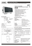
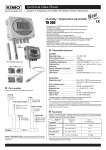
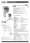
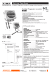
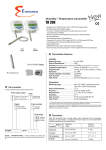
Technical Data Sheet
Pressure • Temperature • Humidity • Air Velocity • Airflow • Sound level
New
Humidistats
HST
standard
IP30
HST
HST
remote
IP65
HST
duct
mount IP 65
Part number
Standard
Duct mount
Remote
Example : HST-A
Model : humidistats HST with a duct mount probe.
Standard
Features of the transmitter
Humidity
±2% of reading ±0,6°C in the range -20 to +5°C
Response time ...................................1/e (63%) 15 s
Resolution ..........................................0,1°C
Type of fluid........................................air and neutral gases
42 mm
100 mm
Measuring range ................................0 to 100 %RH
Unit of measurement..........................% RH
Accuracy *...........................................±2% of reading ±2%RH
in the range of 10 to 90%RH
Response time....................................1/e (63%) 4 s
Resolution...........................................0,1%RH
Type of fluid ........................................air and neutral gases
Temperature
Measuring range...................................0 to +50°C (standard model)
-20 to +80°C (duct mount and remote sensor)
Unit of measurement .........................°C, °F
Accuracy * ..........................................±1% of reading ±0,4°C in the range +5 to+80°C
-
HST
Measuring ranges from 0 to 100 %RH and 0 to +50°C, -20 to +80°C
RCR relay 3A/230Vac. Power supply 24Vac/Vdc
Visual alarm, red LED in front
IP 65 and IP 30 ABS housing, with display
Alternating display of humidity and temperature
Quick and easy mounting with the “1/4 turn” system with wall-mount plate
Working principle : the measurement of temperature and humidity is made
by only one digital component CMOS (complementary metal-oxyde
semiconductor) including a capacitive element and a thermistor.
This technology guarantees an excellent stability in the long term, along
with a great accuracy of the measurement.
To order, just add the code to complete the part number :
Probe
M
A
D
•
•
•
•
•
•
30 mm
110 mm
Features of the housing
Ø13 mm
Duct mount
100 mm
Ø13 mm
42 mm
83 mm
125 mm
Housing ...............................................ABS
Fire-proof class...................................HB as per UL94
Dimensions .........................................see drawing beside
Protection ..........................................IP 30 (standard model)
IP 65 (duct mount and remote sensor)
Display.................................................5-digit LCD. Dimensions 50 x 15 mm
..............................................................Alternating display of humidity and temperature.
Height of the digits .............................10 mm
Cable grip ............................................for cables Ø 7 mm max.
Weight..................................................145 g
Technical specifications
Ø13 mm
Remote
42 mm
140 mm
110 mm
100 mm
Ø13 mm
Output ............................................1 RCR relay 3A/230 Vac
Relay and alarm status .................red LED in front
Set point .........................................2 configurable set points (°C and %RH)
Power supply .................................24 Vac/Vdc ±10%
Consumption.................................2 VA
Electro-magnetical compatibility.......EN 61326
Electrical connection ...................Screw terminal block for cables Ø1.5mm² max.
Connection to PC........................... Kimo RS 232 cable
Working temperature(housing)......0 to +50°C
Working temperature (probe).........0 to+50°C (standard model)
-20 to +80°C (duct mount and remote sensor)
Storage temperature .....................-10 to +70°C
Environment ..................................air and neutral gases
*All the accuracies indicated in this technical datasheet were stated in laboratory conditions, and can be guaranted for
measurements carried out in the same conditions, or carried out with calibration compensation.
Connection
Set point
setting button
f
e
Relay
d
NC..................Normally closed
COM ..............Common
NO .................Normally open
a
DIP switch
Connection to PC
via LCC 100 software
b
Power supply
Vdc .........direct voltage
GND .......ground
Or
a
Relay
terminal block
b
b
Vac .........alternative voltage (phase)
Vac .........alternative voltage (neutral)
c
Cable grip : to insert the cable, it is required to
slightly cut the rubber.
Power supply
terminal block
c
Cable grip
Electrical connections - as per norm NFC15-100
!
This connection must be made by a qualified technician. To make the connection, the transmitter must not be energized.
Or
NC
Relay
terminal
block
Vac ~
Vac ~
COM
NO
Power supply Vdc +
terminal block
Or
GND -
-
+
~
~
Power supply
24 Vac
Class II
Vac
Vac
Power supply
24 Vdc
Neutral Phase
Power supply
24 Vac
Configuration
Configuration of measuring units, set points can be carried out different ways : DIP switch, push-button and/or software
(connections e , f and d on the drawing “connection”).
Configuration of measuring units by DIP switch
To configure the transmitter, please unscrew the 2 screws from the housing,
and then open it.
Identification of the DIP switches
on the electronic board
Electronic board
d DIP switch
1
2
3
4
DIP
switch 1
On-off switch
}
1
2 3 4
DIP
switch 2 Inactive
Setting of units
To configure the transmitter, it must not be
energized. Then, you can make the settings
required, thanks to the DIP switches (as shown
on the drawing beside).
When the transmitter is configured, you can
power it up.
! Caution !
Please follow carefully the combinations beside with the
DIP switch.
If the combination is wrongly done, the following message will
appear on the display of the transmitter “CONF ERROR”.
In that case, you will have to unplug the transmitter, replace the
DIP switches correctly, and then power the transmitter up.
2
• Setting of units
Configurations
To set the measuring unit, please put the on-off switches
3 and 4 as shown beside.
Combinations
°C
1
2
3
4
°F
1
2
3
4
Set points configuration with the push-button
Set point
configuration
button
Electronic
board
Power the transmitter up : it will then display its current configuration.
To modify the configuration, please proceed as follows :
Remove the 2 screws from the housing and open it.
The settings are done with the button located on the electronic board
(see photo beside).
Principle :
- By pressing on this button for more than 3 seconds, you can validate the setting and go to the next setting.
- By pressing quickly on this button, you can increment a value and scroll down the different options or values.
This button enables :
1- to activate/deactivate an alarm (set point)
2- to program the action of the alarm (rising/falling/regulation action)
3- to set the set point value
4- to set the time-delay (temporisation)
AL.O
AL.OFF
0000.0
00.SEC
To set the different options :
1- Activating/deactivating the alarm :
Co F. CONF will be displayed, AL.O
AL.OFF or
After pressing the set point configuration button for more than 3 seconds,
then AL.ON
AL.OFF (depending on the last configuration of the transmitter).
AL.O
AL.OFF (alarm off).
Afterwards, by briefly pressing on this button, you can switch between AL.ON
(alarm on) and AL.OFF
AL.OFF , then you will exit the configuration mode and
To validate your choice, press again for 3 seconds. If you chose AL.OFF
AL.O
switch back to the measurement mode. If you chose AL.OFF
, you will move to the next parameter.
2- Programming the action of the alarm (rising/falling/regulation action) :
Rising action (1 set point) : the alarm will activate when the measure exceeds the set point and will stop when the
measure goes below the set point.
Falling action (1 set point) : the alarm will activate when the measure goes below the set point and will stop when the
measure goes above the set point.
Regulation mode (2 set points) : the set point values will determine the action type. Two possibilities are available:
set point 1 > set point 2
Measurement
set point 2 > set point 1
Measurement
set point 1
set point 2
Alarme set
set point 2
<T>
<T>
<T>
Measure > set point 1 ®
Alarm activation
Measure < set point 2 ®
Alarm stop
set point 2 £
Measure £
set point 1 ®
No change
Time
<T> Time-delay
set point 1
<T>
<T>
<T>
Time
Measure < set point 1 ®
Alarm activation
Measure > set point 2 ®
Alarm stop
set point 1 £
Measure £
set point 2 ®
No change
Press the button for 3 seconds to confirm your choice. You will then move on to the last parameter.
3- Programming the set point value :
The set point is a limit which, when being reached and/or exceeded, activates the relay and the visual red LED alarm.
The first digit will start to blink, by briefly pressing on the button, you can choose if the set point will be either positive (0) or
negative (-). Then press the button during 3 seconds to confirm your choice. The second digit will start to blink. Press the
button briefly to change the value. Then press the button during 3 seconds to confirm your choice. Repeat this sequence until
you have reached the last digit and then confirm the set point. If you selected regulation mode
, you will program the
second set point.
4- Setting of the time-delay (dead band temporisation 60 sec max) :
When the set point is reached and/or exceeded, the time-delay will wait the specified time before energizing the relay, if the
set point is still reached and/or exceeded.
When the first digit starts blinking, press briefly on the button to change the value. Then press the button during 3 seconds to
confirm your choice. Repeat the process until all digits have the desired value and press the button for 3 seconds to confirm 3
your choice.
The programming is now done and the display switches back to the measurement mode.
3
Initialization of the transmitter
When the transmitter is powered up, it initializes and displays the digits 0.0.0.0.0 , and then its configuration including :
- 1 - the measuring range
- 3 - action of the alarm (rising, falling or regulation action)
- 2 - the status of the alarm
- 4 - the set point
- 5 - time-delay (dead band temporisation)
1- The measuring range
L
The following message is displayed :
. This is the low value of the measuring range, and its digit value : ex : - 5.0.0 .
. .0.0 .
The following message is displayed : H.
. This is the high value of the measuring range and its digit value : ex : 10
The arrow displayed (at the bottom or on the right of the screen) is relative to the unit of measurement : ex : from -500 to 1000 Pa.
4- The set point (alarm on)
This message is displayed : ex : 2.5.0 , which means that the alarm
will be activated as soon as the measurement exceeds this value.
If you chose regulation mode
, the second set point will appear.
2 - The status of the alarm
. .ff
. .
When the alarm is off, the following message is displayed : al.o
.
When the alarm is on, the following message is displayed : al.o
.
• When the alarm is off, the transmitter displays
which
confirms
,
the end of initialization and that you can start the measurements .
• When the alarm is on, the transmitter displays the parameters relative to
the relay (set point, program of the alarm, time-delay).
5 - The time-delay (alarm on)
This message is displayed : i.s.e.c .
The temporisation is in seconds (from 0 to 60 sec.).
3 - Action of the alarm (rising or falling action)
If the relay is programmed in regulation mode, the following message is displayed
.
Configuration via software
1
2
3
4
(with the optional LCC100 software)
An easy and friendly way to configure !
You can configure the measuring units, the set point the time-delay.....
For all the parameters (humidity and temperature)
1
2 3 4
Switch 2
Inactive
Switch 1
• In order to balance an eventual drift of the transmitter, you can add an offset to the value displayed by the HST :
=> example : the HST indicates 48%RH, the standard reference indicates 45%RH
=> via the LCC100, you can add an offset of “ -3” to the value.
To access the configuration via software, you must first position the DIP switches, as per the following picture (shown
beside), and then connect the cable to the transmitter (see “connection” drawing).
Please refer to the user manual of the LCC 100 to make the configuration.
!
Caution !
The configuration can be made either via switch, or via software (you can not combine both solutions).
Mounting
A
40 mm
Ø 8 mm
Ø 4,5 mm
7 mm
Maintenance
Please avoid any aggressive solvent.
Please protect the transmitter and its probes from any cleaning product
containing formol, that may be used for cleaning rooms or ducts.
Optional accessories
Options
Power supply class 2, input 230 Vac,
output 24 Vac, ref.KIAL-100A
Configuration software LCC 100 supplied
with connection RS 232 cable
www.kimo.fr
EXPORT DEPARTMENT
Tel : + 33. 1. 60. 06. 69. 25 - Fax : + 33. 1. 60. 06. 69. 29
e-mail : [email protected]
Stainless steel sliding connection
PC connection gland
ABS clamp with connection gland
Stainless steel clamp
Wall-mounting plate for remote humidity probe
Distributed by :
68 mm
A
ABS
plate
50 mm
73 mm
Installation : mount the ABS plate on the wall (this plate is supplied with the
transmitter). Drilling : Ø 6 mm, with the screws and pins supplied with the
transmitter. Insert the transmitter into the plate (see points A of the drawing
shown beside), by tilting it at 30°. Rotate the housing in clockwise direction
until you hear a “click” which confirms that the transmitter is correctly
installed.
For the model with remote sensor,an additional drilling of Ø14 mm must be
done before mounting the plate.
,
After having displayed the configuration, the transmitter displays
which confirms that the nitialization is finished and you can start
the measurements.
.
Ref. FT ang - HST - 10/06 C - We reserve the right to modify the characteristics of our products without notice.
If the relay is programmed in rising action, the following message is displayed :
If the relay is programmed in falling action, the following message is displayed :
This message is displayed : ex : 2.5.0 , which means that the alarm