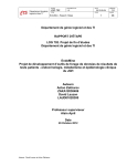
1
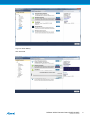
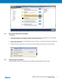
USER GUIDE
REB215-XPRO Extension Board
Introduction
®
This user guide facilitates how to getting started with the Atmel REB215-XPRO
extension board.
The extension board is targeted for evaluating the features and performance of
the Atmel AT86RF215 radio transceiver.
42398A-MCU-03/2015
Table of Contents
Introduction .................................................................................... 1
1. Getting Started ........................................................................ 3
1.1.
1.2.
1.3.
Features ..............................................................................
Design Documentation and Related Links ..................................
Board Assembly ....................................................................
1.3.1.
Connect to a Xplained Pro Board .................................
1.3.2.
In Customer Development Assembly .............................
3
3
3
3
3
2. Performance Analyzer ............................................................. 4
2.1.
2.2.
2.3.
2.4.
Introduction ..........................................................................
Program Installation ...............................................................
Using the Performance Analyzer ..............................................
Typical Board Assembly .........................................................
4
4
7
7
3. Xplained Pro ............................................................................ 9
3.1.
3.2.
Hardware Identification System ................................................ 9
Standard Headers and Connectors ........................................... 9
3.2.1.
Xplained Pro Standard Extension Header ...................... 9
4. Hardware User Guide ........................................................... 11
4.1.
4.2.
4.3.
4.4.
Board Overview .................................................................. 11
Headers and Connectors ...................................................... 11
4.2.1.
J100 Xplained Pro Extension Connector ...................... 11
4.2.2.
J104 & J105 ........................................................... 12
4.2.3.
Serial I/Q Data Interface (J101, J102, J103) .................. 12
4.2.4.
Current Monitoring (J1) ............................................. 13
Board GUI .......................................................................... 13
4.3.1.
LEDs ..................................................................... 13
4.3.2.
Button ................................................................... 13
4.3.3.
SMA Connectors ..................................................... 13
U2 Serial EEPROM ............................................................. 13
5. Persistent Memory ................................................................ 14
6. Agency Certifications ............................................................ 15
6.1.
6.2.
6.3.
6.4.
United State (FCC) ..............................................................
European Union (ETSI) ........................................................
Canada (IC) .......................................................................
Using Limited Modular Certified Products .................................
15
15
16
16
7. Document Revision History ................................................... 18
REB215-XPRO Extension Board [USER GUIDE]
42398A-MCU-03/2015
2
1.
Getting Started
1.1
Features
The REB215 extension board is a template design for the AT86RF215.
1.2
Design Documentation and Related Links
1
The most recent and relevant documents and software for the REB215-Xpro extension board .
1.3
Board Assembly
The extension board provides wireless communication to an Xplained PRO board or to your own prototype for
software development and hardware verification.
1.3.1
Connect to a Xplained Pro Board
The extension board can be connected to any Xplained PRO main board using the extension header.
1.3.2
In Customer Development Assembly
The extension board can be wired into the customer prototype assembly by using an on-board connectors, all
relevant signals are available at on-board connectors.
1
http://www.atmel.com/tools/atreb215-xpro.aspx
REB215-XPRO Extension Board [USER GUIDE]
42398A-MCU-03/2015
3
2.
Performance Analyzer
2.1
Introduction
The Performance Analyzer Firmware with the GUI in Atmel Studio Wireless Composer Extension provides
basic functional RF tests.
A quick start guide and general help is provided in Wireless Composer once started.
2.2
Program Installation
How to install Wireless Composer application, follow the steps:
1
1.
Install Atmel Studio .
2.
After installing the application, launch Atmel Studio.
Navigate to Tools > Extension Manager > Select Extension Manager to install Wireless Composer
Select Wireless and Wireless Composer.
1
http://www.atmel.com/tools/atmelstudio.aspx
REB215-XPRO Extension Board [USER GUIDE]
42398A-MCU-03/2015
4
Log on to Atmel Gallery.
Click download.
REB215-XPRO Extension Board [USER GUIDE]
42398A-MCU-03/2015
5
Restart Atmel Studio, allow help to make changes and the Performance Analyzer GUI is available in the
Tools menu.
3.
If Xplained Pro board is not pre-programmed - program the board with the Performance Analyzer Firmware
available in the "Wireless Performance Analyzer Firmware extension" or from source code provided in ASF
by using the EDBG from Atmel studio.
REB215-XPRO Extension Board [USER GUIDE]
42398A-MCU-03/2015
6
2.3
Using the Performance Analyzer
To get started.
2.4
1.
Connect the Wireless board assembly, with the Performance Analyzer FW programmed, to the PC USB
connector and power on, a COM port should now be available for the kit.
2.
Power on any other wireless node assemblies of similar frequency, running the Performance Analyzer FW,
and use it as a reference.
3.
Start Performance Analyzer GUI, connect to the kit via the COM port and follow the quick start guide.
Typical Board Assembly
The Atmel SAM4L Xplained Pro Evaluation Kit with REB215-XPRO Wireless Extension board.
REB215-XPRO Extension Board [USER GUIDE]
42398A-MCU-03/2015
7
REB215-XPRO Extension Board [USER GUIDE]
42398A-MCU-03/2015
8
3.
Xplained Pro
Xplained Pro is an evaluation platform that provides the complete Atmel microcontroller experience. The
platform consists of a series of Microcontroller (MCU) boards and extension boards that are integrated with
Atmel Studio, have Atmel Software Framework (ASF) drivers and demo code, support data streaming and
more. Xplained Pro MCU boards support a wide range of Xplained Pro extension boards that are connected
through a set of standardized headers and connectors. Each extension board has an identification (ID) chip
to uniquely identify which boards are mounted on a Xplained Pro MCU board. This information is used to
present relevant user guides, application notes, datasheets, and example code through Atmel Studio. Available
1
Xplained Pro MCU and extension boards can be purchased in the Atmel Web Store .
3.1
Hardware Identification System
All Xplained Pro compatible extension boards have an Atmel ATSHA204 CryptoAuthentication™ chip mounted.
This chip contains information that identifies the extension with its name and some extra data. When an
Xplained Pro extension board is connected to an Xplained Pro MCU board the information is read and sent
to Atmel Studio. The Atmel Kits extension, installed with Atmel Studio, will give relevant information, code
examples and links to relevant documents. Table 3-1, “Xplained Pro ID Chip Content” on page 9 shows the
data fields stored in the ID chip with example content.
Table 3-1. Xplained Pro ID Chip Content
Data Field
Data Type
Example Content
Manufacturer
ASCII string
Atmel’\0’
Product Name
ASCII string
Segment LCD1 Xplained Pro’\0’
Product Revision
ASCII string
02’\0’
Product Serial Number
ASCII string
1774020200000010’\0’
Minimum Voltage [mV]
uint16_t
3000
Maximum Voltage [mV]
uint16_t
3600
Maximum Current [mA]
uint16_t
30
3.2
Standard Headers and Connectors
3.2.1
Xplained Pro Standard Extension Header
All Xplained Pro kits have one or more dual row, 20-pin, 100mil extension headers. Xplained Pro MCU boards
have male headers while Xplained Pro extensions have their female counterparts. Note that all pins are not
always connected. However, all the connected pins follow the defined pin-out described in Table 3-2, “Xplained
Pro Extension Header” on page 9. The extension headers can be used to connect a wide variety of
Xplained Pro extensions to Xplained Pro MCU boards and to access the pins of the target MCU on Xplained
Pro MCU board directly.
Table 3-2. Xplained Pro Extension Header
1
Pin Number
Name
Description
1
ID
Communication line to the ID chip on extension board.
2
GND
Ground.
3
ADC(+)
Analog to digital converter, alternatively positive part of
differential ADC.
4
ADC(-)
Analog to digital converter, alternatively negative part of
differential ADC.
5
GPIO1
General purpose I/O.
6
GPIO2
General purpose I/O.
7
PWM(+)
Pulse width modulation, alternatively positive part of
differential PWM.
8
PWM(-)
Pulse width modulation, alternatively positive part of
differential PWM.
http://store.atmel.com/CBC.aspx?q=c:100113
REB215-XPRO Extension Board [USER GUIDE]
42398A-MCU-03/2015
9
Pin Number
Name
Description
9
IRQ/GPIO
Interrupt request line and/or general purpose I/O.
10
SPI_SS_B/GPIO
Slave select for SPI and/or general purpose I/O.
11
TWI_SDA
Data line for two-wire interface. Always implemented, bus
type.
12
TWI_SCL
Clock line for two-wire interface. Always implemented, bus
type.
13
USART_RX
Receiver line of Universal Synchronous and Asynchronous
serial Receiver and Transmitter.
14
USART_TX
Transmitter line of Universal Synchronous and
Asynchronous serial Receiver and Transmitter.
15
SPI_SS_A
Slave select for SPI. Should be unique if possible.
16
SPI_MOSI
Master out slave in line of Serial peripheral interface. Always
implemented, bus type.
17
SPI_MISO
Master in slave out line of Serial peripheral interface. Always
implemented, bus type.
18
SPI_SCK
Clock for Serial peripheral interface. Always implemented,
bus type.
19
GND
Ground.
20
VCC
Power for extension board.
REB215-XPRO Extension Board [USER GUIDE]
42398A-MCU-03/2015
10
4.
Hardware User Guide
4.1
Board Overview
Figure 4-1. Board overview
4.2
Headers and Connectors
The extension board connectors.
4.2.1
J100 Xplained Pro Extension Connector
The Xplained Pro extension connectors, used to connect the extension board to the Xplained Pro board.
Table 4-1. J100 Xplained Pro Extension Header
RF215
Pin
Name
1
ID
Communication line to the ID chip on the
extension board.
2
GND
Ground.
3
ADC(+)
4
ADC(-)
5
GPIO1
LED D2 Yellow for user function.
6
GPIO2
LED D1 Green for user function.
7
PWM(+)
8
PWM(-)
9
IRQ/GPIO
10
SPI_SS_B/
GPIO
11
TWI_SDA
Data line for the two wire interface to
AT24MAC602 serial EEPROM.
12
TWI_SCL
Clock line for the two wire interface to
AT24MAC602 serial EEPROM.
13
USART_RX
14
USART_TX
15
SPI_SS_A
42
SELN
Slave select for SPI. Should be unique if
possible.
16
SPI_MOSI
43
MOSI
Master out slave in line of Serial peripheral
interface. Always implemented, bus type.
Pin
Name
Description
13
RSTN
RESET to RF215.
40
IRQ
Interrupt request line to uC on Xplained Pro
board.
REB215-XPRO Extension Board [USER GUIDE]
42398A-MCU-03/2015
11
4.2.2
Pin
Name
17
RF215
Description
Pin
Name
SPI_MISO
44
MISO
Master in slave out line of Serial peripheral
interface. Always implemented, bus type.
18
SPI_SCK
41
SCLK
Clock for Serial peripheral interface. Always
implemented, bus type.
19
GND
Ground.
20
VCC
Power for extension board.
J104 & J105
J104 and J05 provide to control an external RF analog frontend device, external LNA, PA.
Table 4-2. J104
Pin
RF215 signal
Function
1
FEB24
External Frontend Control for 2.4GHz.
2
FEA24
External Frontend Control for 2.4GHz.
Table 4-3. J105
4.2.3
Pin
RF215 signal
Function
1
FEB09
External Frontend Control for Sub-1GHz.
J105-2
FEA09
External Frontend Control for Sub-1GHz.
Serial I/Q Data Interface (J101, J102, J103)
Low voltage differential signalling (LVDS) interface is used for the data transfer between the AT86RF215 and
an external baseband processor.
Table 4-4. J101- I/Q Data Receiver 2.4GHz
Pin
RF215 signal
1
Function
Ground
2
RXDP24
B+ (Receive)
3
RXDN24
B- (Receive)
4
Ground
5
RXCLKP
A+ (Receive)
6
RXCLKN
A- (Receive)
7
Ground
Table 4-5. J102- I/Q Data Receiver Sub GHz
Pin
RF215 signal
1
Function
Ground
2
RXDP09
B+ (Receive)
3
RXDN09
B- (Receive)
4
Ground
5
A+ (Receive)
6
A- (Receive)
7
Ground
Table 4-6. J103- I/Q Data Transmitter
Pin
RF215 signal
1
2
Function
Ground
TXDP
B+ (Receive)
REB215-XPRO Extension Board [USER GUIDE]
42398A-MCU-03/2015
12
Pin
RF215 signal
Function
3
TXDN
B- (Receive)
4
Ground
5
TXCLKP
A+ (Receive)
6
TXCLKN
A- (Receive)
7
4.2.4
Ground
Current Monitoring (J1)
J1 enables current monitoring using an external multimeter.
Connect multimeter between J1-1 and J1-2 and measure current used.
Warning
When not monitoring current the strap need to be inserted in order to provide power to the board.
Table 4-7. J1 Current measurement
Pin
Function
J1-1
3.3V pin on the AT86RF215
J1-2
3.3V on extension board
4.3
Board GUI
4.3.1
LEDs
There are two LEDs available for use by application SW.
Table 4-8. LEDs
4.3.2
LED
Function
D1 - Green
User defined function
D2 - Yellow
User defined function
Button
There is a button to reset the RF215 device.
Table 4-9. Buttons
4.3.3
Button
RF215 signal
Function
SW1
RSTN
Reset, press to reset
SMA Connectors
There are two SMA connectors - one 2.4GHz transmit and receive and one for Sub-1GHz transmit and
receiver.
Table 4-10. SMA connectors
4.4
Connector
Function
SMA-1
RF input/output for Sub-1GHz Transceiver.
SMA-2
RF input/output for 2.4GHz Transceiver.
U2 Serial EEPROM
The REB215 contains a serial EEPROM, AT24MAC602 and factory programmed MAC addresses available
through the I2C interface of J100.
The memory organisation is as documented in “Persistent Memory” on page 14 . The structure is located
from EEPROM address 0x00, device address ‘1010’.
REB215-XPRO Extension Board [USER GUIDE]
42398A-MCU-03/2015
13
5.
Persistent Memory
A persistent memory space is allocated to store product specific information. The persistent memory is
organized as follows:
Table 5-1. Persistent Memory
Data
Data Type
Size
Structure Revision
uint 16
2 bytes
MAC address
uint 64
Board information – PCBA Name
Board information – PCBA Serial number
8 bytes
1
30 bytes
1
10 bytes
1
ASCII string
ASCII string
Board information – PCBA Atmel Part Number
ASCII string
8 bytes
Board information – PCBA Revision
uint 8
1 byte
Reserved
3 bytes
XTAL Calibration Value
uint 8
1 byte
Reserved
7 bytes
Reserved
4 bytes
CRC
Notes:
uint 16
2 bytes
1
'\0' terminated ASCII string.
The MAC address stored inside the MCU is a uniquely assigned ID for each kit and is owned by Atmel. User
applications can use this unique MAC ID to address the kit.
REB215-XPRO Extension Board [USER GUIDE]
42398A-MCU-03/2015
14
6.
Agency Certifications
6.1
United State (FCC)
This equipment complies with Part 15 of the FCC rules and regulations. To fulfill FCC Certification
requirements, an OEM manufacturer must comply with the following regulations:
1.
Important
The ATREB215-XPRO limited modular transmitter must be labelled with its own FCC ID number, and, if
the FCC ID is not visible when the module is installed inside another device, then the outside of the device
into which the module is installed must also display a label referring to the enclosed module. This exterior
label can use wording such as the following:
Contains FCC ID : VW4A091982. This equipment complies with Part 15 of the FCC Rules.
Operation is subject to the following two conditions:
(1) this device may not cause harmful interference, and
(2) this device must accept any interference received, including interference that may cause
undesired operation (FCC 15.19)
(3) this certificate is valid only while transmit at 2.4GHz ISM band.
Provide SMA connector to connect external antenna for mobile transmitter must provide a separation distance
of at least 20 cm from all persons and must not be co-located or operating in conjunction with any other
antenna or transmitter. Installers must be provided with antenna installation instructions and transmitter
operating conditions for satisfying RF exposure compliance. This device is approved as a mobile device with
respect to RF exposure compliance, and may only be marketed to OEM installers. Use in portable exposure
conditions (FCC 2.1093) requires separate equipment authorization.
Important
Modifications not expressly approved by this company could void the user's authority to operate
this equipment (FCC section 15.21).
Important
This equipment has been tested and found to comply with the limits for a Class A digital device,
pursuant to Part 15 of the FCC Rules. These limits are designed to provide reasonable protection
against harmful interference when the equipment is operated in a commercial environment.
This equipment generates, uses, and can radiate radio frequency energy and, if not installed
and used in accordance with the instruction manual, may cause harmful interference to radio
communications. Operation of this equipment in a residential area is likely to cause harmful
interference in which case the user will be required to correct the interference at his own expense
(FCC section 15.105).
ATREB215-XPRO is limited modular approved and requires separate approval for this module when used on
an application board.
Cet appareil est conforme à la section 15 des réglementations de la FCC. Le fonctionnement de l’appareil est
sujetaux deux conditions suivantes:
(1) cet appareil ne doit pas provoquer d’interférences néfastes, et
(2) cet appareil doit tolérer les interférences reçues, y compris celles qui risquent de provoquer un
fonctionnement indésirable
(3) ce certificat est valable uniquement en transmission à bande ISM 2.4 GHz.
6.2
European Union (ETSI)
The ATREB215-XPRO Module has been certified for use in European Union countries at 2.4GHz ISM Band. If
these modules are incorporated into a product, the manufacturer must ensure compliance of the final product to
the European harmonized EMC and low voltage/safety standards. A Declaration of Conformity must be issued
for each of these standards and kept on file as described in Annex II of the R&TTE Directive.
REB215-XPRO Extension Board [USER GUIDE]
42398A-MCU-03/2015
15
Furthermore, the manufacturer must maintain a copy of the modules' documentation and ensure the final
product does not exceed the specified power ratings, antenna specifications, and/or installation requirements
as specified in the user manual. If any of these specifications are exceeded in the final product, a submission
must be made to a notified body for compliance testing to all required standards.
Important
The 'CE' marking must be affixed to a visible location on the OEM product. The CE mark shall
consist of the initials "CE" taking the following form:
The CE marking must have a height of at least 5mm except where this is not possible on account
of the nature of the apparatus. The CE marking must be affixed visibly, legibly, and indelibly. More
detailed information about CE marking requirements you can find at "DIRECTIVE 1999/5/EC OF
THE EUROPEAN PARLIAMENT AND OF THE COUNCIL" on 9 March 1999 at section 12.
6.3
Canada (IC)
The ATREB215-XPRO Module complies with Industry Canada specifications RSS-210 and RSS – GenIC.
ID for ATREB215-XPRO is 11019A-091982
ATREB215-XPRO is limited modular approved and requires separate approval for this module when used on
an application board.
User manuals for licence-exempt radio apparatus shall contain the following or equivalent notice in a
conspicuous location in the user manual or alternatively on the device or both.
This device complies with Industry Canada licence-exempt RSS standard(s). Operation is subject to the
following two conditions:
(1) this device may not cause interference, and
(2) this device must accept any interference, including interference that may cause undesired operation of the
device.
(3) this certificate is valid only while transmit at 2.4GHz ISM band.
Le présent appareil est conforme aux CNR d'Industrie Canada applicables aux appareils radioexempts de
licence. L'exploitation est autorisée aux deux conditions suivantes:
(1) l'appareil ne doit pas produire de brouillage, et
(2) l'utilisateur de l'appareil doit accepter tout brouillage radioélectrique subi, même si le brouillage est
susceptible d'en compromettre le fonctionnement.
(3) ce certificat est valable uniquement en transmission à bande ISM 2,4 GHz.
Under Industry Canada regulations, this radio transmitter may only operate using an antenna of a type
and maximum (or lesser) gain approved for the transmitter by Industry Canada. To reduce potential radio
interference to other users, the antenna type and its gain should be so chosen that the equivalent isotropically
radiated power (e.i.r.p.) is not more than that necessary for successful communication
Conformément à la réglementation d'Industrie Canada, le présent émetteur radio peut fonctionner avec une
antenne d'un type et d'un gain maximal (ou inférieur) approuvé pour l'émetteur par Industrie Canada. Dans
le but de réduire les risques de brouillage radioélectrique à l'intention des autres utilisateurs, il faut choisir le
type d'antenne et son gain de sorte que la puissance isotrope rayonnée équivalente (p.i.r.e.) ne dépasse pas
l'intensité nécessaire à l'établissement d'une communication satisfaisante.
6.4
Using Limited Modular Certified Products
The ATREB215-XPRO Module is certified under part 15 of FCC rules. The Modular certification
category of this module is “Limited Modular”. The end product (The ATREB215-XPRO kit will be
used by professional users under lab environment) using these modules hence has to undergo compliance
testing and receive a new FCC ID for the final product carrying these modules. Certification of the final product
lies solely with the type of design of the final product.
REB215-XPRO Extension Board [USER GUIDE]
42398A-MCU-03/2015
16
Warning
The Original Equipment Manufacturer (OEM) must ensure that the OEM modular transmitter must
be labeled with its own FCC ID number. This includes a clearly visible label on the outside of the
final product enclosure that displays the contents shown below. If the FCC ID is not visible when
the equipment is installed inside another device, then the outside of the device into which the
equipment is installed must also display a label referring to the enclosed equipment.
Important
This equipment complies with Part 15 of the FCC Rules. Operation is subject to the following
two conditions: (1) this device may not cause harmful interference, and (2) this device must
accept any interference received, including interference that may cause undesired operation
(FCC 15.19). The internal / external antenna(s) used for this mobile transmitter must provide a
separation distance of at least 20cm from all persons and must not be co-located or operating
in conjunction with any other antenna or transmitter. Installers must be provided with antenna
installation instructions and transmitter operating conditions for satisfying RF exposure
compliance. This device is approved as a mobile device with respect to RF exposure compliance,
and may only be marketed to OEM installers. Use in portable exposure conditions (FCC 2.1093)
requires separate equipment authorization.
Important
Modifications not expressly approved by this company could void the user's authority to operate
this equipment (FCC section 15.21).
Important
This equipment has been tested and found to comply with the limits for a Class A digital device,
pursuant to Part 15 of the FCC Rules. These limits are designed to provide reasonable protection
against harmful interference when the equipment is operated in a commercial environment.
This equipment generates, uses, and can radiate radio frequency energy and, if not installed
and used in accordance with the instruction manual, may cause harmful interference to radio
communications. Operation of this equipment in a residential area is likely to cause harmful
interference in which case the user will be required to correct the interference at his own expense
(FCC section 15.105).
REB215-XPRO Extension Board [USER GUIDE]
42398A-MCU-03/2015
17
7.
Document Revision History
Document
revision
Date
Comment
42398A
01/2015
Initial document release
REB215-XPRO Extension Board [USER GUIDE]
42398A-MCU-03/2015
18
Atmel Corporation
1600 Technology Drive, San Jose, CA 95110 USA
T: (+1)(408) 441.0311
F: (+1)(408) 436.4200
|
www.atmel.com
© 2015 Atmel Corporation. / Rev.: 42398A-MCU-03/2015
®
®
Atmel , Atmel logo and combinations thereof, Enabling Unlimited Possibilities , and others are registered trademarks or trademarks of Atmel Corporation in U.S. and
other countries. Other terms and product names may be trademarks of others.
DISCLAIMER: The information in this document is provided in connection with Atmel products. No license, express or implied, by estoppel or otherwise, to any intellectual property right is granted
by this document or in connection with the sale of Atmel products. EXCEPT AS SET FORTH IN THE ATMEL TERMS AND CONDITIONS OF SALES LOCATED ON THE ATMEL WEBSITE,
ATMEL ASSUMES NO LIABILITY WHATSOEVER AND DISCLAIMS ANY EXPRESS, IMPLIED OR STATUTORY WARRANTY RELATING TO ITS PRODUCTS INCLUDING, BUT NOT LIMITED
TO, THE IMPLIED WARRANTY OF MERCHANTABILITY, FITNESS FOR A PARTICULAR PURPOSE, OR NON-INFRINGEMENT. IN NO EVENT SHALL ATMEL BE LIABLE FOR ANY DIRECT,
INDIRECT, CONSEQUENTIAL, PUNITIVE, SPECIAL OR INCIDENTAL DAMAGES (INCLUDING, WITHOUT LIMITATION, DAMAGES FOR LOSS AND PROFITS, BUSINESS INTERRUPTION,
OR LOSS OF INFORMATION) ARISING OUT OF THE USE OR INABILITY TO USE THIS DOCUMENT, EVEN IF ATMEL HAS BEEN ADVISED OF THE POSSIBILITY OF SUCH DAMAGES.
Atmel makes no representations or warranties with respect to the accuracy or completeness of the contents of this document and reserves the right to make changes to specifications and products
descriptions at any time without notice. Atmel does not make any commitment to update the information contained herein. Unless specifically provided otherwise, Atmel products are not suitable
for, and shall not be used in, automotive applications. Atmel products are not intended, authorized, or warranted for use as components in applications intended to support or sustain life.
SAFETY-CRITICAL, MILITARY, AND AUTOMOTIVE APPLICATIONS DISCLAIMER: Atmel products are not designed for and will not be used in connection with any applications where the failure
of such products would reasonably be expected to result in significant personal injury or death (“Safety-Critical Applications”) without an Atmel officer's specific written consent. Safety-Critical
Applications include, without limitation, life support devices and systems, equipment or systems for the operation of nuclear facilities and weapons systems. Atmel products are not designed
nor intended for use in military or aerospace applications or environments unless specifically designated by Atmel as military- grade. Atmel products are not designed nor intended for use in
automotive applications unless specifically designated by Atmel as automotive-grade.