1
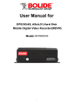
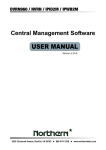
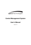
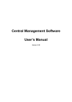
1 User Manual CONTENTS Important Safeguards .............................................................................................................................................................. 1 Chapter 1 Features and Functions ....................................................................................................................................... 2 1.1 Video / Audio .......................................................................................................................................................... 2 1.2 Power supply .......................................................................................................................................................... 2 1.3 Record Mode .......................................................................................................................................................... 2 1.4 Data storage and backup ......................................................................................................................................... 2 1.5 Anti-shock and anti-vibration structure design ....................................................................................................... 2 1.6 Other ....................................................................................................................................................................... 2 Chapter 2 Appearance ............................................................................................................................................................. 3 2.1 Front Panel .............................................................................................................................................................. 3 2.2 Rear Panel ............................................................................................................................................................... 4 2.3 External Cable and Cord ......................................................................................................................................... 4 2.3.1 Power Cord ............................................................................................................................................... 4 2.3.2 A/V Cable................................................................................................................................................... 5 2.3.3 I/O cable .................................................................................................................................................... 6 2.3.4 Alarm I/O.................................................................................................................................................... 7 2.3.5 Speed sensor ............................................................................................................................................ 7 Chapter3 Connecting DVR ......................................................................................................................................................... 8 3.1 The device installation ............................................................................................................................................ 8 3.2 Removeable HDD installation ................................................................................................................................ 9 3.3 Connecting Power Supply .................................................................................................................................... 10 3.4 Connecting Camera and Monitor .......................................................................................................................... 10 3.5 Connecting GPS Antenna (Optional) .................................................................................................................... 10 3.6 Connecting 3G Mould Antenna (Optional)........................................................................................................... 10 3.7 Getting Started ...................................................................................................................................................... 10 Chapter 4 Starting the system ....................................................................................................................................................11 4.1 System Initialization ............................................................................................................................................. 11 4.2 Main Interface....................................................................................................................................................... 11 Chapter 5 DVR Menu.............................................................................................................................................................. 12 5.1 Context-Sensitive Menu ....................................................................................................................................... 12 5.2 Main Menu Preview ............................................................................................................................................. 12 5.3 Main Menu ........................................................................................................................................................... 13 5.3.1 Camera Set ............................................................................................................................................. 13 5.3.2 Record Set .............................................................................................................................................. 13 5.3.3 Network Setup ........................................................................................................................................ 14 User Manual 5.3.4 Video Search .......................................................................................................................................... 15 5.3.5 Device Management .............................................................................................................................. 16 5.3.5.1 HDD Management .......................................................................................................................... 16 5.3.5.2 Alarm Setup .................................................................................................................................... 17 5.3.5.3 Motion Detection ............................................................................................................................ 18 5.3.5.4 Vehicle Setup .................................................................................................................................. 18 5.3.5.5 PTZ Setup ....................................................................................................................................... 18 5.3.6 System Setup ......................................................................................................................................... 19 5.3.6.1 Time Setup ...................................................................................................................................... 19 5.3.6.2 Password Setup ............................................................................................................................... 19 5.3.6.3 Video Setup ..................................................................................................................................... 20 5.3.6.4 System Language ............................................................................................................................ 20 5.3.6.5 System Information......................................................................................................................... 20 5.3.6.6 System Maintain ............................................................................................................................. 20 5.4 Menu Lock ............................................................................................................................................................ 21 5.5 Video Search ......................................................................................................................................................... 21 5.6 PTZ Control .......................................................................................................................................................... 21 5.7 Start Record .......................................................................................................................................................... 21 5.8 Stop Record .......................................................................................................................................................... 21 Chapter 6 EXT2 Drive .............................................................................................................................................................. 22 6.1 System requirement .............................................................................................................................................. 22 6.2 EXT2 Setup .......................................................................................................................................................... 22 6.3 Record export software ......................................................................................................................................... 23 Chapter 7 Net Viewer Program .............................................................................................................................................. 25 7.1 How to install Net Viewer program ...................................................................................................................... 25 7.2 Off-line working ................................................................................................................................................... 25 Chapter 8 Specifications .......................................................................................................................................................... 28 8.1 Troubleshooting .................................................................................................................................................... 28 8.2 Accessories(Optional) ..................................................................................................................................... 30 User Manual Important Safeguards 1. This equipment should be installed with care. Quick stops and excessive force may cause the equipment to damage or overturn. 2. Never push objects of any kind through openings of this equipment and / or spill liquid of any kind on the equipment as they may touch dangerous voltage points or short out parts that could result in a fire or electric shock. 3. Do not attempt to service this equipment yourself. Refer all serving to qualified service personnel. 4. Do not install near any heat sources, dusty and intense magnetic field. 5. Do not use this equipment near water or in contact with water. 6. Unplug this equipment and refer all servicing to qualified service personnel under the following condition: When the equipment exhibits a distinct change in performance, or When liquid is spilled or objects have fallen into the equipment. 7. Protect the power cord from being walked on or pinched particularly at plugs, convenience receptacles and the point where they exit from the equipment. 8. Operator or installer must remove power, BNC, alarm and other connections before moving the equipment. 9. The equipment should be installed at someplace where passenger or driver can not be easy to damage device, camera, alarm and cord and other accessory. 10. This equipment should be operated only from the type of power source indicated on the marking label. If you are not sure of the type of power, please consult your equipment dealer. 1 User Manual Chapter 1 Features and Functions 1.1 Video / Audio ● H.264 video compression format, and supports D1, HD1 and CIF recording format. ●ADPCM audio compression format. 1.2 Power supply ● Support wide range of power supply, DC 9V~32V.; ● When connecting power in to a opposite end, system will activate auto-protection function to avoid the DVR and power supply damage. ● Provide stable power supply (12V) for each camera and monitor to prevent the equipment from voltage surge damage; ● Support DVR auto switch on/off and delay on/off function when car ignition is on/off 1.3 Record Mode ● DVR auto switch-on when car ignition is on, Scheduled record. ● Alarm can activate record function on the sleep mode. ●Support record on schedule when car ignition is on ●Support record on 4-CH alarm and DVR auto switch on while opening the car door. ●Support Motion detection record 1.4 Data storage and backup ● Retractable HDD box easy to install, system support a internal 2.5” SATA HDD. ● With USB2.0 port, and support backup record and update software via U flash disk or removable hard disk. ● Support Retractable HDD directly connect to PC for HDD data export, and playback via Netviewer. 1.5 Anti-shock and anti-vibration structure design ● Stable aluminum structure, ● Dual shock absorption design. 1.6 Other ●Graphics operation interface and embedded Linux 2.6 Live operation system; ● Support real-time quadplex operation: Live, Record, Playback and Backup. ● transmit video images to integrated surveillance platform via wireless network; ● Adjustable pack time for recorded file; ●Support IR remote control ●Support self-recovery function 2 User Manual Chapter 2 Appearance 2.1 Front Panel 1 3 4 5 6 1. 2. 3. 4. 2 7 Retractable HDD Box Retractable HDD Box Key / Power on/off USB 2.0 Port Indicator a. PWR Indicator: light on when power is on b. HDD Indicator: light on when HDD is available; light flash when HDD is writing data. c. REC Indicator: light on when recording is in progress d. SD Card Indicator: light on when SD card is reading/writing data e. VLOSS Indicator: light on when video loss is triggered. f. GPS Indicator: light on when installing GPS mould and have no received GPS signal and light flash when received GPS signal g. ALM Indicator: light on when any alarm is triggered. h. Net Indicator: light on when wireless Net is installed and on the status of working i. ERR Indicator: light on when error occurs j. HEAT Indicator: light on when heat mould is working (Optional) 5. IR Receiver 6. UIM Card Port: it is available only when the corresponding Net mould is installed. 7. SD Card Port MCU port: used to upgrade MCU of main board DEBUG Port: used to debug the main unit. 3 User Manual 2.2 Rear Panel 1 2 3 6 4 5 7 8 1 Power Supply Jack 5 WIFI Antenna Port 2 Ethernet Port 6 IR-Ext input 3 GPS Antenna Port 7 A/V Jack 4 Cellular Antenna Port 8 Sensor I/O Port 2.3 External Cable and Cord 2.3.1 Power Cord BATT Pin (Red): Power input (connected to car battery+) GND Pin (Black): Power GND (connected to car battery -) ACC Pin (Yellow): Ignition signal input (connected to car power level) The 6-pin plug will be connected to power supply jack of rear panel. Red and black wires connected to car battery + and – respectively, yellow wire to ignition wire. Reminder: 1)Make sure the power supply is between 9V and 32V to avoid the device damage due to higher voltage. 2)It is very import for you to make the wires insolated. 3)Yellow wire must be connected to ignition wire, otherwise, the device will not support delay power off function and you will miss all the video record. 4 User Manual 2.3.2 A/V Cable 1. Audio output (white BNC port) 2. Video output (Black BNC port) 3. CH4 Audio input (White BNC port) 4. CH4 Video input (Black BNC port) 5. CH3 Audio input (White BNC port) 6. CH3 Video input (Black BNC port) 7. CH2 Audio input (White BNC port) 8. CH2 Video input (Black BNC port) 9. CH1 Audio input (White BNC port) 10. CH1 Video input (Black BNC port) 11-12. Monitor+12 V power supply output (Red = Positive pole (+); Black = Negative pole (-)) 13-14.CH4 Camera+12V power supply output (Red=Positive pole (+); Black = Negative pole (-)) 15-16.CH3 Camera+12V power supply output (Red=Positive pole (+);Black = Negative pole (-)); 17-18 CH2 Camera + 12V power supply output (Red=Positive pole (+);Black = Negative pole (-)) 19-20 CH2 Camera + 12V power supply output (Red=Positive pole (+);Black = Negative pole (-)) 5 User Manual 2.3.3 I/O cable I/O cable port definition Port Name Description 485 Port RS485 8 Pin: RS485A / 15 Pin: RS485B Alarm input SENSOR1~4 4-CH alarm input Alarm input SENSOR5~8 4-CH alarm input, can act as emergency button. Alarm output ALARM0~1 2-CH alarm output Speed SPEED Speed sensor, connect to speed pulse Sensor Note: SENSOR1-8 is off or connected to GND, they are acted as low level. 6 User Manual 2.3.4 Alarm I/O The device connected to eight groups of alarm input and two groups of alarm output. When brake plate is stepped on illustrated in below Picture, mobile DVR can detect high level. Alarm output belongs to level output and driving capacity is 200 MA. If driving power is too strong, the relay is required. Please refer to the below connection configuration. 2.3.5 Speed sensor 1. Connect speed sensor input of Camera to pulse output of car sensor 2. If speed meter have pulse signal output, the speed sensor input of camera can directly connected to the ouput port of speed meter. If speed meter has no pulse signal output, that means you need to connect pulse signal output of speed sensor to the speed meter input. 3. Camera will receive pulse signal from speed sensor through Menu setting. 4. How to calculate pulse count per kilometer. Generally the wheel turn a circle, sensor speed will generate eight or sixteen pulses. However, it is difficult to calculate the pulse counts by hand in the practical application. We calculate the value by driving one kilometer. 7 User Manual 2.4 Remote Controller Key title 1-4 0、 、5-9 Key Function Channel select CH1~CH4; numeric key numeric key ALL Multiple CH display Menu Enter Main Menu / Exit ▲ Up direction arrow ▼ Down direction arrow ◄/ SEL Left/right direction arrow, Decrease/increase parameter value Select/Edit key Rewind key Search / Play key Fast Forward Key ● Rec. Key Pause Key ■ Stop Key Audio Testing Mute Testing Chapter3 Connecting MDVR 3.1 The device installation Installation mode for the device includes horizontal installation and rack installation. 1. Horizontal installation: Place the equipment on a stable installation surface horizontally, and then tighten it to the surface through four screws. 2. Rack installation: When limited space lead the equipment to not install horizontally, user can adapt rack installation to mount on the side and wall of car. Depart the device from anti-vibration rack before installing, And then please follow the below steps to install the device: 1. Loosen three screws on the front panel 8 User Manual 2. Take the device away from the anti-vibration rack. 3. Install anti-vibration rack to vehicle with screws. 4. Fix the device back the anti-vibration rack with previous three screws. 5. Finish the device installation. 3.2 Removeable HDD installation Please follow the below steps to install the HDD: 1. Take out removable HDD from the HDD box; 2. Loosen the screw and remove PCB board; 3. Remove the upper cover of HDD box; 4. Put the HDD on the anti-vibration rack and connect SATA port of data cable to HDD; 5. Fix the HDD to the HDD box with screws; 6. Install the upper cover back HDD box with screws; 7. Tighten the PCB board back HDD box with screws; 8. Finish the installation processing. 9 User Manual 3.3 Connecting Power Supply The 6-pin plug will be connected to power supply jack of rear panel. Red and black wires connected to car battery + and – respectively, yellow wire to ignition wire. Reminder: 1. MDVR use DC power supply, please connect it properly; 2. Working voltage range for MDVR is from 9V to 32V. Too high or low voltage make DVR not work normally. 3. Power cable must be enough thick so that it can bear 5A current. 3.4 Connecting Camera and Monitor Connect respectively camera and monitor to the corresponding port on the rear panel shown as section 2.2-Rear Panel. 3.5 Connecting GPS Antenna (Optional) Connect GPS Antenna to the GPS port on the rear panel shown as section 2.2-Rear Panel. Please make sure the front of GPS Antenna have no any blockages to avoid affect its signal receive and transmittal 3.6 Connecting 3G Mould Antenna (Optional) Connect 3G Mould Antenna to the Cellular port on the rear panel shown as section 2.2-Rear Panel. Please make sure the front of 3G Mould Antenna has no any blockages to avoid affect its signal receive and transmittal. 3.7 Getting Started After connecting all the DVR accessories well, you can start DVR using key. 10 User Manual Chapter 4 Starting the system 4.1 System Initialization Connect the power cable of DVR to power supply and press the [Power] button, you will see the initialization screen shown as below 4-1. Picture 4-1 4.2 Main Interface After finishing the initialization processing, system will enter into Main interface screen. Picture 4-2 is the main interface defaulted by system, which is showing no video input status. Once there are video inputs, the interface will display live images from the cameras. Picture 4-2 In main interface mode, if you click 1, 2, 3 or 4 on the Remote Controller, the CH1,2,3 or 4 will be maximized to full screen, by clicking All or 5 again, the display will be returned back to 4-split mode. Clicking [SEL] button on the Remote Controller will pop up Context Sensitive Menu; by clicking [Up/Down] button, you can select menu items; when clicking [SEL/MENU] button again, you will exit the Context-Sensitive menu. Note: If DVR is not connected to Hard Driver, “H” Character will appear in the screen, MDVR will automatically restart after two minutes under the default mode. If you want to close the [Auto restart after two minutes] function, please refer to Section 5.2.5.1 – HD management. 11 User Manual Chapter 5 MDVR Menu 5.1 Context-Sensitive Menu On the Main Interface mode, Press [SEL] key on the Remote Controller to pop up a Context Sensitive Menu. Now you could perform parameter setting and control for Main Menu, Menu Lock, Video Search, Start Record, Stop Record and PIP Mode etc. Picture5-1 5.2 Main Menu Preview Camera Record Network Rec. Search HDD Manage Alarm Setting Main Menu Device Management Motion Detect Vehicle function PTZ Setting Exit Time Setting User password System Video Setting Language Select System Information System Maintenance 12 User Manual 5.3 Main Menu In Main Interface mode, click right key of mouse to pop up Context Sensitive Menu, and then highlight and select [Main menu] item to enter into Main menu. Now user can freely set parameters for [Camera], [Record], [Network], [Search], [Device] and [System] as per user’s needs. Picture5-2 If system interface is lock, please firstly input password to unlock before entering into [Main Menu]. Details please refer to section 5.4– Menu Lock. 5.3.1 Camera Set Go to [Main MenuCamera] to set up the title and Position of each channel (Shown as Picture 5-3). You can also adjust image brightness, saturation, and contrast and hue settings of each channel after entering into [Color] menu and set up whether each channel can be previewed or not under Live display and/or Record mode. Please note that the title of each channel support up to eight characters. Picture5-3 Display time while in live view: allows you setup display time in the live mode. Display time while recording: the option is set to ON, the display time while recording will appear in the screen when play backing record; set to Off, the display time while recording disappear in the screen. Below is the Color Menu where you can adjust image brightness, saturation, contrast and hue parameters of each channel.(shown as picture 5-4). Friendly Reminder: 1、The modifications will be available only when clicking [APPLY] button on the bottom of the sub-menu windows and being prompted to save and then clicking [ok] button. Picture5-4 2、If you want to cancel the modification, click [Exit] button to exit the menu. 3、When clicking [DEFAULT] button, all system values will be reset to default value. 4、System default value indicates the value pre-set at the factory. 5.3.2 Record Set Click [Main MenuRecord Setup] option to enter into the interface shown as Picture 5-5. The [Record Setup] menu allows you set up recording status (on/off) of each channel, it also allows you setup recording image resolution and quality, and turns audio on/off. Picture5-5 13 User Manual The [Record Setup] menu allows you set up recording status (on/off) of each channel, it also allows you setup recording image resolution and quality, and turn audio on/off. Channel: :Once a channel is set to “on” the channel can record, and is set to “off” the video from the channel will not be recorded Resolution: include three options – D1, HD1 and CIF. Quality:give you three options – Best, Good and Normal – to choose the quality of your recorded images. Audio: When Audio is set to “On”, system will also record audio from the channels and will have audio output on playback mode; if it is set to “off” you can not record audio and will have no audio output available on playback mode. Rec. Mode: allow you select record mode (Always and scheduled record) Pack Time: :allow you select pack time for recorded file(15, 30, 45 and 60 min) To record 24 hours a day set the [Rec Mode] to Always. To record on motion or on schedule, select the “Schedule” option from pull-down menu, you can find a new schedule open shown as Picture 5-6. It will include 24 columns from 0~23 each representing a house of the day and 7 rows for each day of the week. Each box represents an hour in the week. After entering into [Schedule] option, you can select your desired channel(s) (<All>, <CH1>,<CH2>,<CH3> and <CH4>) from the pull-down menu. To setup weekly schedules, tick-select the check-box of the recording status you want (Alarm, General, or No Record) and then click on each box in the schedule time line. Picture5-6 You can use the [From – To] pull-down menus and Copy button to copy settings from one day to another day or all days. RED = ALARM GREEN = NORMAL WHITE = NO RECORD. 5.3.3 Network Setup Click [Main MenuNetwork] to enter into below window, and select Network type (such as Static, CDMA2000 and WCDMA) and set Media port and Web port as per user’s network environment. And then user can visit and operate her DVR remotely. Note: Generally user no need to modify network type. We have defualted to specified mode as per different model, such as D5604 defaulted to “Static”, D5604GE to “CDMA2000” and D5604GW to “WCDMA” Picture5-7 On the [WCDMA/CDMA2000] mode, APN, dial code, user name and password are provided by ISP, and DNS is fixed. Device name:indicate CMS display mark, herein set by yourself. MTDS Server IP:indicate media server address (also IP address of CMS server. MTDS Server Port: indicate media port Frame rate: allow you select 3fps, 5fps, 8fps, 10fps and 12fps. Bit rate: allow you select 16kbps, 32kbps and 64kbps. Auto connect: When set to “On” system will auto-connect to network after disconnecting. Picture5-8 14 User Manual All the parameters you set are available only when you click [Ok] and after system is restarted. Enter into the [Network set] interface again and [State] column will display the characters “Connecting” shown as Picture 5-9. The 3G dialing will be successful till one IP code appear on the [State] column. Picture 5-9 When selecting [Static] mode, you will directly input IP address, subnet mask,Gateway and media/web port etc. Note: On the [Static] mode, you could visit the MDVR remotely only when the MDVR is connected to cable network. Picture 5-10 5.3.4 Video Search Click [Main MenuVideo Search],or click [▶]button on the remote controller to enter into below window shown as Picture 5-11. Time Search: In the Video Search screen, user can search for a specific date and time for a recording and view it in Playback mode. This is useful for hunting a specific recording of an incident if you know the date and time it occurred. The DVR supports 4-CH playback simultaneously. Picture5-11 Date search: In the Video Search screen, user can search for all the recordings in a specific date. To execute a video search, highlight and select the date numeric field, system will start to playback from the first recoding of the specific date. File list: :Click [File list] button to enter into the [File List] screen, all the recording events will be found and listed in chronological order. You can playback a desired recording file. Group Backup: :Once you tick-select [Group Backup] option, system will automatically backup the recordings of other channel at the same time quantum when backing up one channel’s recordings. You can use the Playback Controls on the remote control to operate the Fast Forward (X2, X4 and X8), Slow play (1/2, 1/4 and 1/8 speed), Play, Pause/Frame, Rewind(X2, X4 and X8). When ending playback, DVR will return back to previous menu. File List In the [Video Search] screen, click [File List] option to enter into the below window illustrated in picture 5-12. Select a desired date/time and click [Search] button, and the video recording for the time quantum will appear in the screen. And you also can filter the recordings you want to view by the Channel or recording mode based on date/time search. First: go to the first page on the list. When you view other pages, clicking [First] button brings you back to Page one. Picture5-12 15 User Manual Prev: go to the previous ones of current page. Clicking [Pre] button will take you back the previous ones of current page (except the first page). Next: go to the next ones of current page. Clicking the [Next] button will take you to the next ones of current page (except the last page). Last: go to the last page. Clicking the [last] button will make you enter into last page quickly. All: allows you select all the recording events on the current page. Inverse: allows you select other recording events on the current page except those you have selected currently In the [File List] mode, if you wish to backup recordings, please tick-select the BAK check-boxes which correspond to the recordings and click [Backup] button Picture5-13 When backup processing ends, system will prompt you “Backup success!” shown as Picture 5-14 Note: 1、 Backup file will be saved as H264 format; you can convert it to AVI format using the Multimedia Player program that comes with the DVR or through the net-viewer program, so you can use any player which supports AVI format. Picture5-14 2、 Please make sure you have connected backup device well before backing-up. 5.3.5 Device Management [Device management] object includes HDD, Alarm, Motion, Vehicle and PTZ.Click [Main MenuDevice Management] to enter into the interface shown as Picture 5-15. Picture5-15 5.3.5.1 HDD Management In the [Device Management] screen, click [SEL] to enter into the below window shown as Picture 5-16. HDD Status (status of the currently installed hard drive) –If the hard is not installed properly you will see a message saying NO DISK FOUND. Total space-Total size of the hard drive currently installed. Free space-Total free space available on the hard drive installed. Useable Rec. Time-Free space currently available in hours Picture5-16 HDD Alarm – If set to “Reboot”, the DVR will auto reboot after two minutes when system have detected current HDD is not properly installed or not formatted; if set to IGNORE, the DVR will cancel the 16 User Manual auto-reboot function even if system has detected NO DISK FOUND. Overwrite-When set to ENABLE the DVR will record over the oldest files on the hard drive. This is the default setting. And probably the most useful, as the DVR will record the events as they happen. However, it does mean that you’ll get import events off the DVR before they’re overwritten. If [Overwrite] is set to DISABLE the DVR will stop record once HDD is full. Whilst you won’t lose old footage, you run the risk of missing new events as they happen. Be sure you want to do this before selecting it. Period – You can set the Overwrite period accordingly when OVERWRITE set to ENABLE. HDD Format – Formatting the HDD will erase all the data (i.e. footage) which is stored on it, and re-create the FAT (file allocation table). USB Format - if you have a USB flash drive connected to the DVR, you can format that, too. This is also erase all the data on the drive. To format the HDD or USB, click the [HDD/USB Format] button respectively and click [OK] button shown as left Picture 5-17. Picture5-17 Unlike a VCR which records to a tape, your DVR records footage to the internal hard drive. Therefore, it’s an important first step when configuring your DVR to make sure that the hard drive (HDD) options are correctly set. 5.3.5.2 Alarm Setup Click [Main MenuDevice ManagementAlarm Setup] option and then enter into the below interface shown as Picture 5-18 Now you can perform the alarm settings for all the alarm modes. Click pull-down menu beside [I/O status] option and select the I/O Channel (1-3 or 4-6) as per your actual requirement. Picture5-18 I/O STATUS:Options include High, Low and off. When set to “Low”, I/O status Alarm will be triggered once sensor level is high, on the contrary, when set to “High”, sensor level is low; when set to “Off” there are no alarm triggered. HDD Loss: When the option is set to ON, buzzer will release the alarm sound and “H” mark will appear on the screen once HDD loss or HDD not available; when set to OFF, “H” character still appear on the screen but have no alarm sound heard. HDD space: When the option is set to ON, the alarm will be triggered and release the alarm sound when HDD space is not enough; or set to OFF, have no alarm sound heard. Video Loss: When the option is set to ON, Live image will disappear on the screen and system will release the alarm sound once video signal lost; when set to OFF, Live image will also disappear on the screen but have no alarm sound heard. Alarm Type: allow you select according alarm type Alarm Manage: allow you set how to deal with alarms, including output 1 (off, 10s, 20s, 40s and 60s), output 2 (off, 10s, 20s, 40s and 60s), buzzer (off, 10s, 20s, 40s and 60s) and Duration (30s, 1min, 2min and 5min). 17 User Manual Alarm Type Video Loss Function Sends alarm when DVR can’t receive video signal (such as camera damage, cable broken or damaged or power supply malfunction). Motion When an object moves into motion detection area, alarm will be triggered. You can Detection adjust sensitivity level to suit the needs of your actual application environment. I/O Status HDD loss System can convert alarm signal triggered by external sensor into signal identified by system. When Hard Drive is not detected (HDD damage, power supply malfunction), or HDD auto-overwrite is off, and free space is not enough, an alarm will be triggered. List 5-1 5.3.5.3 Motion Detection Picture5-19 You can set up motion detection in a specific area for one camera. Click [Main MenuDevice ManagementMotion Detection] to enter into the below interface shown as Picture 5-19. Channel Status: Video motion detection can be turned on or off for each camera. SENSITIVITY: This option allows you to set sensitivity level of motion detection from 1 to 4 with 4 being the most sensitive. MD Area: This option allows you setup the MD area for the channel you wish to be sensitive to motion. The channel will be separated into a 13X10 grids. When any object moves into the motion detection area, and the area where the object is located is displayed in red and motion detection will be triggered. In the semi-transparent area the motion detection is not activated. Picture5-20 5.3.5.4 Vehicle Setup Record LP: allows you set if the license plate number display on the recorded data or not. Preview LP: allows you set if the license plate number appear on Live screen or not. Record GPS: allows you set if the GPS info display on the recorded data or not. Preview GPS: allows you set if the GPS info appears on Live screen or not. License Plate: you can set the car license plate here and the model supports the plate with Chinese character. Speed Measurement From: allow you get speed measurement source from GPS signal or Sensor signal Delay power off: you can set how long DVR is delayed power off after car ignition is off. Options include <off, 1min, 5min, 10min, 20min, 30min, 40min, 50 min and 60min>. Picture 5-21 5.3.5.5 PTZ Setup Picture 5-22 Note: If user want to perform speed measurement by sensor, please connect one wiring in green provided to speed sensor firstly When car starts to move, enter into [Parameter setting] option and click [Start] button to start speed measurement, and click [Stop] button till car have been driving for one km, and then click [Save]button to save and exit the [parameter setting] menu. 18 User Manual Picture5-23 5.3.6 System Setup Enter into [Main menuDevice PTZ Setup] to select the channel you wish to control and set PTZ protocol (Pelco-D or Pelco-P), Baud Rate fixed (9600), Data bit (8), Stop bit (1), Parity Check (None) and Address Code respectively. Please make sure the above mentioned channel settings must match with the settings of the PTZ camera. For PTZ camera connection method, please refer to Rear Panel configuration. You can set Date/Time, User permission, Video, Language, System info and System Maintenance. Picture5-24 5.3.6.1 Time Setup In the [System Setup] screen, highlight and click [Date/Time] option to enter into the below window. Picture5-23 1. You can check and setup current date/time and time related properties, also modify system display time and date/time display format and setup DST status and mode etc. 2. Click [APPLY] button to save and exit the above setting. Picture5-25 5.3.6.2 Password Setup In the [System Setup] screen, highlight and click [Password] icon to enter into [Password setup] interface. 1. Set [device ID] and [Password Enable] option; 2. Click [Apply] button to save and exit current setting. Picture5-26 When enabling password to [On] first time, you can set [User Password] and [Admin Password] respectively. Password is consist of numeric character 0~9 with a specific length -6 bit. Friendly Reminder: User only has a permission to access [Video Search] menu. But Administrator has full authority over Main Menu operations. Picture5-27 19 User Manual 5.3.6.3 Video Setup Click [Main MenuSystem infoVideo Setup] to enter into the below interface shown as Picture 5-28. Herein user can set video system (PAL, NTSC); and volume setup as well. Note: the above setting is available after system restart. Click [Volume setup] button to enter into the below picture 5-29. Picture5-28 Click [Save] button after adjusting volume value. Picture5-29 5.3.6.4 System Language 1. Click [Main MenuSystem SetupSystem Language] to enter into the interface shown as Picture 5-30 and select your desired system language. 2. Click [Apply] button to save the above setting and exit the interface. Picture5-30 5.3.6.5 System Information Click [Main MenuSystem SetupSystem information] and then enter into below interface. Now user can check the current Device Type, software version and MAC address. Picture5-31 5.3.6.6 System Maintain To recovery system ex-factory default settings, update system software (firmware) and set system auto-maintenance, please enter into [Main MenuSystem SetupSystem Maintain] option to perform the above-mentioned setting. Auto Maintain: The [Auto Maintain] option is defaulted to “On” and set system auto reboot every day 00:00 and you can also set system auto reboot regularly as per user’s need. System Update: 1、You can use a USB memory for updating; 2、Do not take out the USB memory during the update. 3、When the updating is done, system will automatically restart 4、Please manually recovery ex-factory default after system rebooting. Picture5-32 Load Default: If [Load Default] is selected, you can initialize the system to the ex-factory default Reboot: :If [Reboot] is selected, system will auto reboot manually. 20 User Manual 5.4 Menu Lock Considering a system safety feature you can click [SEL] button on the remote controller to lock system interface when leaving the DVR. Note: The [Menu Lock] function will be available only when user have set user password. Detail please refer to the section 5.3.6.2 Picture5-34 Picture5-35 Picture 5-36 Picture5-33 If you want to login to the DVR again, you would input device code and password to unlock the interface shown as Picture 5-34. 5.5 Video Search Pop up the Context sensitive Menu to quickly enter into [Video Search] Menu. We have introduced how to search and playback video recording in previous section. Details please refer to section 5.3.4 – Video Search. 5.6 PTZ Control We introduced setting PTZ parameters previously in chapter 5.3.5.5. Here we will discuss how to operate PTZ controls. Pop up the Context sensitive Menu to highlight and enter into [PTZ control] menu (shown as Picture 5-32). Now user can control the camera with Pan, Tilt and Zoom capabilities. Click [Zoom-/+] button to zoom in / out the image; Click [Focus -/+] button to focus the image; Click [Iris -/+] button adjust iris to open or close. 5.7 Start Record Pop up Context sensitive Menu to enter into the [Start Record] option. Now you can start manual record function, or you also can click [Rec.] button on the Front panel or Remote controller to activate manual record. 5.8 Stop Record To stop record quickly, please pop up Context sensitive Menu to highlight and enter into [Stop Record] option or click [Stop] button 21 User Manual Chapter 6 EXT2 Drive You must firstly install EXT2 setup before you backup the removable HDD via USB cable or playback HDD data via Net-viewer on PC. 6.1 System requirement Compatible system: Windows xp/vista/win7 Basic hardware configuration: CPU: Pentium 4 processor (2.0GHz or above) / Memory: 1GB or above 6.2 EXT2 Setup It is recommended that you close all other application before the setup. Please follow up the below steps for installation: 1. Enter into the [HDD Tool] file, 2. and then double-click to run the Ext2setup.exe file, and this will install ext2 on your computer Picture 6-1 3. Click [Next] button to continue Picture 6-2 4. Click [Install] to continue with the installation 22 User Manual Picture 6-3 5. After finishing installation, you need to restart the computer. Please click [OK] button to restart the computer. Note: If you can’t normally install the EXTSetup.exe on Vista or Win7 system, please right-click the program to enter into its [Options] menu shown as Picture 6-4 Tick-select the [Compatibility mode] option and click [Apply] and [Confirm] button. Picture 6-4 Then install the program again. Note: If you still not identify the EXT2 system, please install “Bak 1-Ext2Fsd” program from the provided software CD (attached installation instruction on the software CD). 6.3 Record export software Due to using special file system, we can’t read the index documents with *.nvr format and must export the file via special export software. Before exporting, please connect HDD box to PC via USB cable and system will auto-install the export software. After finishing the installation, enter into [My computer] to find one new local disk (X), that means system have identify and load the HDD. 23 User Manual 1. Run the NvrExport.exe in the “Export_tool” file 2. If you want to export all the directory, please tick-select [Directory] option, and export all the files, tick select [File] option shown as Below. When user need to export one day’s record, please select [Directory] option, and export some hours’ record, please select [File] option. 3. After selecting expot type, click[ ] button on the right of [Source file] column, after enter into sub-window, select the file you want to export; 4. Select the targeted route you desire to save from [Destination] column; 5. And then click [ ] button to start exporting the record file. Note: a) The processing bar point again single file, If you have selected multiple files or all the directory, the processing bar will appear in the screen frequently. b) If you want to stop the export processing, please click [ c) The exported file will be converted to the files with *.264 format and user can playback these files via netviewer. 24 ] button. User Manual Chapter 7 Net Viewer Program 7.1 How to install Net Viewer program (1) (2) (3) (4) (5) Insert the software CD into your CD-ROM drive; Open the CD file; Double-click the setup file to run the installation program; Follow up the instruction to finish the installation step by step. Finish the installation processing; you will see the interface shown as Picture 7-1. 7.2 Off-line working Click the [Off-line] button on the right-upper corner of the screen shown as Picture 7-1 Picture 7-1 Enter into the [Off-line] interface shown as Picture7-2.Now you are allowed to playback the backup file Picture 7-2 Click [Add] button on the right-down corner to pop up the window shown as Picture 7-3. Picture 7-3 25 User Manual Enter into and select the file you want to playback shown as Picture 7-4. Picture 7-4 Highlight and open the file you desire to playback shown as Picture 7-5 Picture 7-5 Now the record file has been added to the interface shown as Picture 7-6. Picture 7-6 Also allow you select all the backup files and add them to the play interface shown as Picture 7-7 & Picture 7-8. Picture 7-8 Picture 7-7 26 User Manual On the playback mode, select one record file and click [Play] button to playback the backup record shown as Picture 7-9. Now you can control its processing through the play control-bar on the bottom of the screen. Slide the volume control bar to adjust the volume. Select one record file and click [Delete] button to delete the file. Picture 7-9 Click the […] button to enter into origin file and target file’s route respectively Click the [264 to AVI] button to enter into the interface shown as Picture 7-10. Picture 7-11 Picture 7-10 Click the [Convert] button to convert *.264 to AVI format shown as Picture 7-12 Picture 7-12 27 User Manual Chapter 8 Specifications DEVICE PARAMETER Video System Compression Format Video Input /Output Audio Input /Output Display Resolution Frame rate SPECIFICATION NTSC / PAL(Optional) Video: H.264 ; Audio: 8kHz*16bit ADPCM 4-CH Input / 1-CH output 4-CH Input / 1-CH output D1:704×576(PAL) Single CH PAL:25 fps ,NTSC:30 fps Record Resolution Record frame rate Image Quality HDD Record Mode PAL: CIF(352*288) HD1(704*288) NTSC:CIF(352*240) HD1(704*240) Playback Alarm I/O Alarm Mode USB Port Ethernet Interface Wireless Network GPS IR Remote Control Power Supply Power Consumption D1 (704*576) D1 (704*480) PAL:25fps@D1/50fps@HD1/100fps@CIF NTSC:30fps@D1/60fps@HD1/120fps@CIF Best / Good / Normal Support 2.5” SATA HDD Record power on while car ignition is on、Scheduled record, Manual record, Motion detection and sensor triggered Record Pack Time Backup 704×480 (NTSC) 15/30/45/60 Min(settable) Support connect PC to HDD box via USB cable to export record datas and support U flash disk and removable HDD for backup Playback, F. forward, Rewind, Slow play frame by frame. 4-CH alarm input / 2-CH alarm output Motion detection, Sensor Triggered, Video Loss, HDD full and HDD error Support removable HDD and U flash disk for backup and U flash disk update Support RJ45 Ethernet interface Support wireless video/Audio transmission via 3G network (Optional) Support embedding latitude/longitude and speed info to video stream (Optional) Operational Temperature Operational Humidity Dimension(mm) Support IR remote control Wide range of Power Supply,DC 9V-32V Less than 10W (exclude HDD) -10℃~+40℃ 10%~90% 223(L)X 209(W)X 75.4(H) 8.1 Troubleshooting 1. 2. 3. Q: What can I do if the system does not detect the HDD? A: Check if the power supply system is properly connected and data cord and power cables are securely connected. Q: We have changed the password but do not remember the new password, how can we access the system? A: If you forget system password, enter 0800808 to reset the password Q: We are not getting any video signal on the DVR, what is wrong? 28 User Manual A: Check camera video cable and connections; or check monitor video cable and connections; or confirm that the camera has the power and / or check camera lens setting. 4. Q: Why some channels display just a blank screen even if they receive video sources? A: Check if the camera is connected to the system properly displays the image; check if the camera is properly supplied with power. 5. Q: Can the DVR have problems if it gets too hot, how can I prevent this? A: The DVR has a fan to help it dissipate heat while it is running. Please place the DVR in a place where there is good air circulation and away from heat sources to increase stability and life of the DVR. 6. Q: “Record” Can not work normally, how to deal with? A: Check if the current screen is in Play mode, pressing [Stop] button to exit the Play mode and then you can enter into the [Record] function. 7. Q: Why the Remote Controller can’t work normally? A: Check if the battery is power off; or check if the Remote Controller is broken. 8. Q: Can we records whilst playing-back? A: Yeah, you can do it. The system support you records whilst playing-back. 9. Q: Can we erase some recorded file from DVR. A: Considering the safety factor, you can’t delete the recorded file directly from the device. When you actually erase all the recorded files, please select HDD format function 10. Q: Why does the Buzzer keep sounding? A: Please check if motion detection is on and the system has detected motion, make sure the HDD is being detected and has sufficient space available; check if video has lost etc. 11. Q: Why can’t stop [Stop] function? A: Pressing [Stop] button only can stop manual record. If you want to stop Scheduled record, please revise to [No Record] during this period. 29 User Manual 8.2 Accessories( (Optional) ) Remote Controller Software CD Alarm I/O Cable Power Cord A/V Cable User Manual Two Keys GPS Mould Antenna(Optional) EVDO Mould Antenna(Optional) Triple-headed USB data cable 30 User Manual The material in this document is the intellectual property of our department . No part of this manual may be reproduced, copied, translated, transmitted, or published in any form or by any means without our department prior written permission. Our products are under continual improvement and we reserve the right to make changes without notice. But no guarantee is given as to the correctness of its contents. We do not undertake any responsibility for the harms cause by using our product. The model of the products in the user's manual only for recognition, but these names also perhaps are belong to other company's registered trademark or the copyright. The product picture may differ from the actual product, only for your reference. The accessories will probably be different according to the different selling areas. For details of accessories, please refer to your local distributor. Cop yright res erve d ٛ ٛ ٛ ٛ ٛ 31