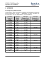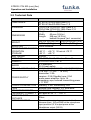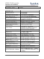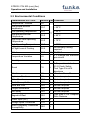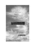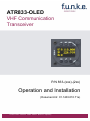
1
k.e.
ATR833-OLED
VHF Communication
Transceiver
P/N 833-(xxx)-(2xx)
Operation and Installation
(Dokument-Nr. 01.1403.010.71e)
f.u.n.k.e. means – fabrication · utilities · network · know-how · engineering
ATR833 / P/N 833-(xxx)-(2xx)
Operation and Installation
Change History
Description of Change
Revision Date
1.00
13.01.2011 FAV – First Release – 2-Knob-HMI
2.00
31.05.2011
2.01
22.06.2012
2.02
10.06.2013
3.00
22.01.2014
3.01
24.11.2014
New cable harness
New remote control, beginning with SW V6.4
New cable harness
Extended control menue Sw V7.0
Information about dual-watch-operation
Change of company name to
f.u.n.k.e. AVIONICS GmbH
Information about antenna cable chapter4.8
Inserted changed setting of Sideton volume
from SW V7.3 in chapter 2.4.6
List of the Service Bulletins (SB)
Services bulletins are to be inserted in the manual and to be put down
in this table.
SB Number
Rev.
No.
Issue Date Entry Date Name
Part Number
Survey of Variants
Description
P/N 833-(200)-(200)
New Generation – 2-knob-HMI
P/N 833-(201)-(200)
Extended control menue SW V7.0
P/N 833-(301)-(210)
P/N 833-(302)-(210)
New housing variant (weight reduction) and
new SW V7.2
Modified INT-display and new sidetone
volume control from SW V7.3
Document-No.: 01.1403.010.71e / Revision: 3.01
2
ATR833 / P/N 833-(xxx)-(2xx)
Operation and Installation
CONTENTS
1
1.1
1.2
1.3
1.4
2
GENERAL ............................................................................................................................................... 5
SYMBOLS ................................................................................................................................................... 5
ABBREVIATIONS .......................................................................................................................................... 5
CUSTOMER SUPPORT ................................................................................................................................... 6
FEATURES .................................................................................................................................................. 6
OPERATION ........................................................................................................................................... 7
CONTROLS ................................................................................................................................................. 7
ON/OFF ................................................................................................................................................... 9
DISPLAY..................................................................................................................................................... 9
BASIC SETTINGS ........................................................................................................................................ 11
2.4.1
VOL - Volume ............................................................................................................................. 12
2.4.2
SQL - Squelch ............................................................................................................................. 12
2.4.3
DIM – Display Brightness........................................................................................................... 13
2.4.4
VOX – Voice Detection (Speech Threshold for Voice Activated Intercom) ................................. 13
2.4.5
DWM – Dual Watch Volume Reduction .................................................................................... 14
2.4.6
INT - Intercom-Volume .............................................................................................................. 14
2.4.7
EXT - Volume of the External Audio Input ................................................................................. 15
2.5
FREQUENCY SETTING.................................................................................................................................. 16
2.5.1
Automatic 8.33 / 25 kHz Channel Width Selection .................................................................... 16
2.5.2
Manual Frequency Input ........................................................................................................... 16
2.5.3
Recall a Frequency from the User Memory ............................................................................... 17
2.5.4
Recall a Frequency from the List of the 10 Last Used ................................................................ 18
2.5.5
Store a Frequency into the User Memory .................................................................................. 18
2.6
DUAL WATCH OPERATION .......................................................................................................................... 20
2.7
TRANSMISSION ......................................................................................................................................... 22
2.8
RECEPTION............................................................................................................................................... 22
2.1
2.2
2.3
2.4
3
CONFIGURATION ................................................................................................................................. 23
SPC – CHANNEL SPACING ........................................................................................................................... 23
DPY – ENERGY SAVING MODE (AUT. DISPLAY DARKENING) .............................................................................. 24
PTT-BUTTON SELECTION ............................................................................................................................ 25
EXT – EXTERNAL AUDIO INPUT’S BEHAVIOR ................................................................................................... 26
MICROPHONE INPUT SENSITIVITY ................................................................................................................. 27
3.5.1
MLS – Standard Microphone Pilot/Left ..................................................................................... 27
3.5.2
MLD – Dynamic Microphone Pilot/Left ..................................................................................... 27
3.5.3
MRS – Standard Microphone Copilot/Right .............................................................................. 27
3.5.4
MRD – Dynamic Microphone Copilot/Right .............................................................................. 27
3.6
TST – TEST MODE .................................................................................................................................... 29
3.7
MASTER RESET ......................................................................................................................................... 29
3.1
3.2
3.3
3.4
3.5
4
4.1
4.2
4.3
4.4
4.5
4.6
3
INSTALLATION ..................................................................................................................................... 30
ADVICES AND TIPS ..................................................................................................................................... 30
TELECOMMUNICATION DATA ....................................................................................................................... 30
SCOPE OF DELIVERY .................................................................................................................................... 30
UNPACKING AND INSPECTING THE EQUIPMENT ............................................................................................... 31
MOUNTING .............................................................................................................................................. 31
EQUIPMENT CONNECTIONS ......................................................................................................................... 32
4.6.1
Microphone-Connection ............................................................................................................ 32
4.6.2
Headset-Connection .................................................................................................................. 33
4.6.3
Audio-Input................................................................................................................................ 33
4.6.4
Remote Control Panel................................................................................................................ 33
Document-No.: 01.1403.010.71e / Revision: 3.01
ATR833 / P/N 833-(xxx)-(2xx)
Operation and Installation
4.7
WIRING ................................................................................................................................................... 34
4.7.1
Conductor Cross Section ............................................................................................................ 34
4.7.2
Connector – Pin Allocation ........................................................................................................ 34
4.7.3
Wiring with Cable Harness BSKS833S/BSKS833D ...................................................................... 36
4.8
ANTENNA ................................................................................................................................................ 38
4.8.1
Antenna Selection...................................................................................................................... 38
4.8.2
Antenna Cable ........................................................................................................................... 38
4.8.3
Installation Recommendation ................................................................................................... 38
4.9
MICROPHONE / INTERCOM SETTINGS ............................................................................................................ 39
4.10
POST-INSTALLATION CHECK ................................................................................................................... 39
4.11
DRAWINGS ......................................................................................................................................... 40
4.11.1
Dimensions ................................................................................................................................ 40
4.11.2
Mounting Advices ...................................................................................................................... 40
5
5.1
5.2
5.3
APPENDIX ............................................................................................................................................ 42
FREQUENCY/CHANNEL-PLAN....................................................................................................................... 42
TECHNICAL DATA ...................................................................................................................................... 43
ENVIRONMENTAL CONDITIONS..................................................................................................................... 45
Document-No.: 01.1403.010.71e / Revision: 3.01
4
ATR833 / P/N 833-(xxx)-(2xx)
Operation and Installation
1 GENERAL
This manual contains information about the physical, mechanical and
electrical characteristics, as well as information about installation and
operation of the aeronautical VHF voice radio ATR833.
1.1 Symbols
Advices whose non-observance can cause radiation
damage to the human body or ignition of combustible
materials.
Advices whose non-observance can cause damage to the
device or other parts of the equipment.
Information
1.2 Abbreviations
Abb.
DIM
EXT
INT
MIC
PTT
SEL
SQ
VOL
VOX
5
Name/subject
Dimming
External audio input
Intercom
Microphone
Push-To-Talk
Selection
Squelch
Volume
Voice activation
Definition
Display Brightness
Volume of external audio signal
Volume of board-internal intercom
Key to activate radio transmission
Noise suppression radio reception
Volume of radio reception
Volume threshold for voice-activated
intercom
Document-No.: 01.1403.010.71e / Revision: 3.01
ATR833 / P/N 833-(xxx)-(2xx)
Operation and Installation
1.3 Customer Support
In order to facilitate a rapid return of shipments in case of repairs, please
follow the instructions of the input guide “Reshipment RMA” provided at
the Service-Area within the f.u.n.k.e. AVIONICS GmbH web portal
www.funkeavionics.de
Any suggestions for improvement of our manuals are
welcome. Contact: [email protected]
Information on software updates is available at f.u.n.k.e.
AVIONICS GmbH.
1.4 Features
• VHF communication transceiver with 6W output power in 57 mm
format
• Frequency range 118,000 to 136,975 MHz
• Automatic selection of 8,33/25 kHz channel spacing
• 4 microphone inputs (2 x standard, 2 x dynamic)
• Voice controlled intercom for up to 4 microphones, can be
deactivated for use with external intercom
• Dual-watch technology, simultaneous monitoring of two
frequencies
• Auxiliary audio input
• Memory for up to 100 user-definable named frequencies
• User-defined frequency list exportable/importable to/from PC (via
RS232) - PC software available at www.funkeavionics.de
• Easy recall of the 10 last used frequencies
• OLED display for best readability under all conditions
• Configurable energy saving
To avoid unintentional permanent transmission, the
transmitter automatically stops transmission after two
Minutes of uninterrupted operation.
Document-No.: 01.1403.010.71e / Revision: 3.01
6
ATR833 / P/N 833-(xxx)-(2xx)
Operation and Installation
2 OPERATION
2.1 Controls
Use together to adjust volume, squelch or other setting
SET
Short press:
Choose item to be adjusted
with
Very long press:
Access configuration menu
VOL/SEL
Rotary knob
Adjust value or select item given within
the display's lower left corner:
Chosen with SET :
adjust VOLume, squelch, etc.
Chosen with MEM :
SELect item from list of frequencies
ON/OFF
MEM
(Radio must
be on)
Short press:
Access user
frequency memory /
list of last used
frequencies
Long press:
In MEM only: store
frequency/name
DW
Activate /
Deactivate
dual watch
reception of
standby
frequency
CHANGE
Swap active
and standby
frequency
CURSOR
Short press:
Set underline to select
which value to be
changed with
Long press:
In MEM only: add name
to memory item
FREQ
Rotary knob
Change underlined
value
Use together to change standby frequency
7
Document-No.: 01.1403.010.71e / Revision: 3.01
ATR833 / P/N 833-(xxx)-(2xx)
Operation and Installation
I/O
ON/OFF
Switch On press button for approx. 0.5 s
Switch Off press button for approx. 2 s
DW
DUAL
WATCH
Activates/deactivates the mode for mutual
reception
of
standby
frequency
(display shows DW instead of SBY)
SET
1. Choose item VOL, SQ, VOX, DIM etc.
(each adjusted by
)
press button shortly
2. Shortcut to volume setting
press button for at least 1.5 seconds
3. Enter configuration menu
press button for at least 5 seconds
SET
►
CURSOR
1. Move underline within standby frequency,
to be adjusted by
press button shortly
2. Add name to frequency within memory
press button for at least 1.5 seconds
▲▼
CHANGE
Swap active and standby frequency
1. Access user defined frequency list (MEM
list).
press button shortly once
MEM
MEM
2. Access list of 10 last used frequencies
(LST list)
press button shortly twice
3. Store active frequency to selected memory
(only for MEM list)
press button for at least 1.5 seconds
1. Adjust volume or other item selected by
VOL / SEL
SET (VOL, SQ, VOX, DIM etc.)
Rotary
2. Select frequency from user memory or list
Knob
of last used frequencies
FREQ
Rotary
Knob
Change
the
underlined
(i.e. adjust standby frequency,
character when entering name)
Document-No.: 01.1403.010.71e / Revision: 3.01
value
or input
8
ATR833 / P/N 833-(xxx)-(2xx)
Operation and Installation
2.2 ON/OFF
Turn the device on with I/O
ON:
I/O press button for 0.5 s
OFF:
I/O press button for 2 s
After turning-on the display shows the software version as follows:
ATR833
v7.0
(Example)
Device Name
ATR833
Software-Version
e.g. v7.0
The Start Screen indicates device type and software version. After that
screen the device changes into normal operation (direct input mode).
The radio starts with the same frequencies and settings from before
being switched off.
2.3 Display
Use of active frequency:
TX = transmitting
RX = receiving
Te = timeout (solve and push
PTT to re-enable transmissions)
Fixed label for
active frequency
Label for standby
frequency:
DW = dual watch active
SBY = no dual watch
Item chosen by
SET , or when
accessing
frequency list:
Adjust value or
select number
with
9
Cursor marking:
Set position with ► , adjust
value with
ACT RX 118.000
SBY RX 124.910
VOL 03 ABCDEFGH BAT
Use of standby
frequency:
RX = receiving
in dual watch
mode
Active
frequency
Standby
frequency
Low Battery warning
User-defined name, when
selecting frequency from
user memory
Document-No.: 01.1403.010.71e / Revision: 3.01
ATR833 / P/N 833-(xxx)-(2xx)
Operation and Installation
Display
Meaning
ACT
Fixed label for active
frequency
SBY
Label for standby frequency, Dual watch mode allows
when no dual watch activated intermittent monitoring of
standby frequency activity
DW
Label for standby frequency,
when dual watch mode
activated
Dual watch mode allows
intermittent monitoring of
standby frequency activity
118.000
Active Frequency
Frequency used for
transmissions and
receptions
124.910
Standby frequency
May be monitored in dual
watch mode
RX
Receiving on this frequency
Usually on active
frequency; can also happen
on standby frequency when
dual watch activated
TX
Transmitting on active
frequency
PTT pressed
Te
Transmission ended
automatically after 2 minutes
continuous transmission
Press PTT shortly to
re-enabel transmissions
VOL 03
Volume level for receiving
SQL 03
Squelch level
DIM 07
Display brightness
VOX 05
Vox level
Speech level that activates
the intercom
DWM -2
Dual watch mute
Reduction in volume for
dual-watch-reception on
standby frequency
INT 04
Intercom volume
Document-No.: 01.1403.010.71e / Revision: 3.01
Remark
Radio signal strength
threshold required for
reception; suppresses
noise and weak/distant
transmitter
10
ATR833 / P/N 833-(xxx)-(2xx)
Operation and Installation
Display
EXT 02
Meaning
Volume of external audiosignals
Remark
Set to 00, if no external
device attached, to prevent
noise pickup
MEM 00
Item from user memory
Substitutes standby
frequency; can have name,
if provided by user. Active
frequency can be stored
into this entry with long
press on MEM
LST 00
Item from list of last used
frequencies
Substitutes standby
frequency
ABCDEFG
User-provided name for
frequency within user
memory
Displayed while selecting
from user memory, when
the user has provided a
name for this specific
memory entry
BAT
Very low supply voltage
Transmission only with
reduced power possible
(decreased radio range!)
F1 … F7
Internal failure
Device must be sent back
to the manufacturer
2.4 Basic Settings
To choose between the following settings, use the SET button:
0.
1.
2.
3.
4.
5.
6.
….
VOL ...... Volume (chosen by default)
SQL ...... Squelch
DIM ....... Display Brightness
VOX ...... Speech level required to activate the intercom
DWM ..... Dual watch mute
INT ........ Intercom volume
EXT ....... Volume of external audio signals
back to Volume
The return to the default display (VOL) is carried out by a long press of
SET or happens automatically after 12 seconds of inactivity)
The chosen setting can be adjusted by the
11
rotary knob.
Document-No.: 01.1403.010.71e / Revision: 3.01
ATR833 / P/N 833-(xxx)-(2xx)
Operation and Installation
2.4.1 VOL - Volume
Can be reached by a long press of the SET button, but is also
automatically chosen by the radio after 12 seconds of user inactivity.
Adjusts the volume of received radio signals by turning the
knob. The higher the value, the louder the reception of radio signals.
ACT
123.450
SBY
118.910
VOL 03
Range: 01 – 16
The VOL setting controls the volume of received radio
signals only, not the volume of the intercom or the external
audio input – these are set separately with INT and EXT .
2.4.2 SQL - Squelch
By shortly pressing the SET key once, with the help of the
rotary knob the squelch level can be adjusted. (Note: This is not related
in any way to the intercom functionality.)
This is a threshold that has to be exceeded by radio signal levels from
other transmitters, in order to activate the reception circuitry. The higher
the number, the stronger the radio signals have to be in order to be
received.
ACT
123.450
SBY
118.910
SQL 07
Range: 01 - 10
The setting for the squelch depends on different factors. For motor
aircrafts an initial higher setting is typically appropriate, gliders may use a
lower value. A lower number means higher input sensitivity. This allows
reception of weaker signals (radio stations at higher distance), but can
also result in pickup of own-aircraft radio interference sources (engine,
strobe lights).
Document-No.: 01.1403.010.71e / Revision: 3.01
12
ATR833 / P/N 833-(xxx)-(2xx)
Operation and Installation
The default Squelch setting is 05. At higher values, weak
signals could be suppressed.
2.4.3 DIM – Display Brightness
By shortly pressing the SET key twice, with help from the
rotary knob the display’s illumination can be adjusted.
123.450
ACT
SBY
118.910
DIM 08
Range: 01 – 10
2.4.4 VOX – Voice Detection (Speech Threshold for Voice
Activated Intercom)
By shortly pressing the SET key three times, with the help of the
rotary knob, the threshold volume VOX for intercom voice
detection can be adjusted. (Note: This is not related in any way to radio
reception or squelch.)
VOX defines the crew’s speech volume that is required to activate the
intercom functionality. The higher the value, the louder you need to
speak in order to activate the intercom.
Exception: VOX 01 corresponds to “always on”
The internal filter circuitry has the ability to distinguish between engine
noise and speech.
ACT
123.450
SBY
118.910
VOX 05
Range: 01 – 10
In case of very noisy backgrounds or use of uncompensated
microphones, the automatic VOX functionality may not work satisfyingly.
In these cases, it is possible to deactivate the VOX automatism with VOX
01, and to use an external intercom-switch.
13
Document-No.: 01.1403.010.71e / Revision: 3.01
ATR833 / P/N 833-(xxx)-(2xx)
Operation and Installation
2.4.5 DWM – Dual Watch Volume Reduction
By shortly pressing the SET key four times, with help from the
rotary knob the lowering of the volume level (“mute”) for
receptions on the standby frequency (when having dual watch active)
can be controlled. This allows acoustic distinction between both
frequencies.
For further information about the dual watch mode see 2.6.
123.450
ACT
SBY
118.910
DWM -2
Range: -8 – 00
-8 is highest muting (dual watch reception at much lower volume)
00 is no muting (dual watch reception at same volume)
2.4.6 INT - Intercom-Volume
The intercom functionality is the onboard crew-internal communication
for multiseater aircraft.
By shortly pressing the SET key five times, the intercom volume level
can be controlled by the
rotary knob. The higher the value, the
higher the intercom volume.
A change in the intercom volume level also changes the volume of the
sidetone. The sidetone is an audible feedback of the own voice to the
headset, i.e. you hear yourself speak. This feature supports a natural
speech behaviour.
The intercom can be activated in two ways:
• Automatically, i.e. whenever someone speaks into a microphone
(i.e. voice activated intercom = VOX, see 2.4.4).
• Manually, i.e. by use of an external intercom switch (cable overview
see 4.7.3.1).
ACT
123.450
SBY
118.910
INT 03
Range: 01 – 10
Document-No.: 01.1403.010.71e / Revision: 3.01
14
ATR833 / P/N 833-(xxx)-(2xx)
Operation and Installation
2.4.7 EXT - Volume of the External Audio Input
By shortly pressing the SET key six times, with help from the
rotary knob, the volume from the connected external audio signals
(Warning tones, music, etc…) can be set.
The higher the value, the higher the volume of the external audio signal.
A value of 00 deactivates the external audio input.
ACT
123.450
SBY
118.910
EXT 03
Range: 00 - 10
When no other device is connected to the external audio
input, the input should be muted by selecting 00, in order to
prevent noise by pickup of on-board interferences.
The priority of the external audio input in comparison to radio
receptions can be configured, see 3.4.
15
Document-No.: 01.1403.010.71e / Revision: 3.01
ATR833 / P/N 833-(xxx)-(2xx)
Operation and Installation
2.5 Frequency Setting
Frequency setting is always done by the two steps of
1. entering a new standby frequency to the desired value, and then
2. interchanging the new standby frequency and the previous active
frequency by using ▲▼ .
Entering a new standby frequency can be done by
a) manual input,
b) recall of previously stored frequencies from the user memory, or
c) recall from the list of the last 10 used frequencies.
2.5.1 Automatic 8.33 / 25 kHz Channel Width Selection
Whether a frequency is used with channel width 8.33 kHz or 25 kHz, is
automatically determined by the value of the frequency entered, and
requires no additional user activity.
The numbering scheme that is used for distinction of the two channel
widths is internationally standardised by the ICAO, and consistently used
in official documents (like e.g. VFR navigation charts) as well as in the
voice phraseology used by ATC radio communication.
Channels used with 25 kHz width are entered in multiples of 25kHz:
123.500, 123.525, 123.550, 123.575, 123.600 etc. These are compatible
with the old 25kHz-only radios. To use the same frequencies with
8.33kHz width, the frequency values entered are increased by 5kHz:
123.505, 123.530, 123.555, 123.580, 123.605 etc.
For more detailed information please refer to chapter 5.1 – but as said
above, for correct channel width selection this knowledge is not required.
2.5.2 Manual Frequency Input
The standby frequency is input by
• selecting with the ► button which part of the frequency to
change, and
• changing the selected part with the
rotary knob.
The selected part of the frequency is marked with the underline.
▲▼ interchanges the newly set standby frequency and the former active
frequency.
Document-No.: 01.1403.010.71e / Revision: 3.01
16
ATR833 / P/N 833-(xxx)-(2xx)
Operation and Installation
In order to speed up the entering of new frequencies, it is
possible to configure the radio to allow entering of those
frequencies only that are used with 25 kHz channel width.
Please refer to chapter 3.1 for information on this
configuration.
However, when choosing this option, please keep in mind to
re-enable 8.33 kHz channel selection before flying into areas
where 8.33 kHz channels are used.
When having the channel selection configured for 8.33 kHz steps (see
3.1), the frequency is input in three steps:
123.450
→ 123.450 → 123.450
When having the channel selection configured for allowing 25 kHz
channels only (see 3.1), the frequency is input in two steps:
123.450
↔ 123.450
2.5.3 Recall a Frequency from the User Memory
To access the user memory frequency list, press MEM once, and select
one of the 100 memory entries with the
turn knob.
The selected memory entry substitutes the former standby frequency.
In the lower row of the display, the number of the memory entry selected
is indicated by [MEM xx] (with xx = 00 … 99); if a name has been
provided by the user for this memory entry, it is displayed next to the
memory entry number.
ACT
123.450
SBY
121.270
MEM 17 HAMBURG
Entry number (Range: 00 – 99)
▲▼ interchanges the newly set standby frequency and the former active
frequency, and leaves the memory list menu.
If no input is done for 12 Seconds, the device returns to the standard
view, too.
17
Document-No.: 01.1403.010.71e / Revision: 3.01
ATR833 / P/N 833-(xxx)-(2xx)
Operation and Installation
2.5.4 Recall a Frequency from the List of the 10 Last Used
The radio automatically keeps track of the last 10 used active
frequencies. To access this list, press MEM twice, and select one of the
10 list entries with the
turn knob. The selected memory entry
substitutes the former standby frequency.
The number of the selected list entry is given in the display’s lower row.
ACT
123.450
SBY
118.700
LST 01
Entry number (Range: 00 – 10)
List entry „00“ contains the last standby frequency from the
MEM menu.
Key ▲▼ interchanges the newly set standby frequency and the former
active frequency, and leaves the last used list menu.
If no input is done for 12 Seconds, the device returns to the standard
view.
2.5.5 Store a Frequency into the User Memory
The active frequency can be stored into any entry of the user memory.
This is achieved by a long press on MEM when having the user
memory entry to be overwritten selected.
The following example stores the frequency 124.350 MHz of KONSTANZ
into the user memory entry 07:
Document-No.: 01.1403.010.71e / Revision: 3.01
18
ATR833 / P/N 833-(xxx)-(2xx)
Operation and Installation
• Display (Example)
Step
1. Have frequency to be stored set
as active frequency
ACT
124.350
SBY
135.700
VOL 03
2. Enter memory list:
Press MEM once shortly in order to
access the user memory. (This
overwrites the former standby
frequency.)
3. Select the memory position to be used
with
4. Overwrite the selected memory entry
with a long press of MEM .
ACT
124.350
SBY
122.000
MEM 00 KEMPTEN
ACT
124.350
SBY
121.270
MEM 07 HAMBURG
124.350
ACT
SBY
124.350
MEM 07
You can now leave the user memory access by pressing MEM twice or
by waiting for the timeout.
Alternatively, you can add a name of up to 8 characters to the
selected memory entry:
While having the memory entry
selected, i.e. coming from step 4 above
when adding the name to the new
stored frequency, or else coming from
step 3 above when adding the name to
an existing memory entry:
ACT
124.350
SBY
124.350
MEM 07
5. Place the cursor into the name field
with a long press of ►
19
Document-No.: 01.1403.010.71e / Revision: 3.01
ATR833 / P/N 833-(xxx)-(2xx)
Operation and Installation
6. Enter the name
124.350
• by changing the selected character with ACT
124.350
, and advancing the selection with SBY
► , just as when manually entering a
MEM 07 KONSTANZ
standby frequency.
7. Store the name
• either with a long press of MEM ,
• or with a long press of ► .
ACT
124.350
SBY
124.350
MEM 07 KONSTANZ
You can now leave the user memory access by pressing MEM twice or
by waiting for the timeout (12 seconds).
2.6 Dual Watch Operation
The ATR833 comprises one receiver, therefore DUAL-Watch
(simultaneously monitoring two frequencies) is implemented by
alternating automatically between the active and the standby frequency.
With dual watch mode active, basically the standby frequency is tuned in,
shortly interrupted in regular intervals by tuning in the active frequency
for a fraction of a second.
Every then detected radio signal on the active frequency has priority, and
pauses the dual watch monitoring of the standby frequency, as long as
the reception/transmission continues on the active frequency.
Transmissions are always done one the active frequency.
The dual watch mode is activated by pressing DW , and indicated by a
changing the “SBY” label for the standby frequency to “DW”.
ACT
123.450
DW
135.700
VOL 05
The dual watch mode is deactivated by pressing DW again, and by any
operations changing either of the frequencies.
Document-No.: 01.1403.010.71e / Revision: 3.01
20
ATR833 / P/N 833-(xxx)-(2xx)
Operation and Installation
SQL has to be set to 02 at least, as without proper squelch
functionality the radio would not be able to detect whether on
the active frequency a reception takes place.
In order to have an audible distinction between receptions on the active
and the standby frequency, it is possible to receive the receptions from
the standby frequency with a lower volume. Please refer to chapter 2.4.5
for information onto this feature “dual watch volume reduction”.
Quick approach:
• Select or enter a standby frequency which shall be additionally
monitored.
• Set SQL with the SET key and the
of at least 02.
rotary knob to a value
• Activate dual watch with DW (DW is shown)
• As soon as no reception is determined on the active frequency, the
mutual monitoring between active and standby frequency starts.
• In order to deactivate dual watch: press DW once more or change
the frequency.
Don’t forget to interchange the active and standby
frequencies, before answering a call on the standby
frequency.
Using dual-watch requires switching between the active and
the standby frequency. Therefore it may happen that calls
on the active frequency cannot be monitored completely. As
the result we recommend not to use dual-watch in airspaces
where listening watch is required.
21
Document-No.: 01.1403.010.71e / Revision: 3.01
ATR833 / P/N 833-(xxx)-(2xx)
Operation and Installation
2.7 Transmission
By pushing the PTT button, the device starts transmission on the active
frequency. The operation of the transmission is indicated by “TX” in front
of the frequency used.
ACT TX 123.450
SBY
135.700
VOL 05
In order to avoid unintended transmissions, e.g. when having the PTT
button stuck (“stuck mic”), the transmitter automatically stops after two
minutes of transmission, and „TX“ is substituted by „Te“.
In order to re-enable transmission in this case, release PTT and push it
again.
When having more than one PTT button and microphone
equipped, it can be configured (chapter 3.3) to use only one
PTT button for transmissions.
2.8 Reception
When receiving, a „RX“ is shown in front of the active frequency. When
having dual watch active (see 2.6) this can be on the standby frequency,
too.
ACT RX 123.450
SBY
135.700
VOL 05
Document-No.: 01.1403.010.71e / Revision: 3.01
ACT
123.450
DW RX 135.700
VOL 05
22
ATR833 / P/N 833-(xxx)-(2xx)
Operation and Installation
3 CONFIGURATION
A very long press of SET (5 seconds) accesses the configuration
menu. The configuration menu is used for fundamental settings.
To choose between the following settings, use the SET button:
1. SPC ..... Channel spacing
2. DPY ..... Automatic display darkening
3. PTT ...... PTT key selection
4. EXT...... Behavior of the external audio input
5. MLS ..... Sensitivity of the left standard microphone input
6. MLD ..... Sensitivity of the left dynamic microphone input
7. MRS ..... Sensitivity of the right standard microphone input
8. MRD .... Sensitivity of the right dynamic microphone input
9. TST ...... Activation/deactivation of the test mode (for maintenance)
….Leaving configuration menu / back to VOL
(can also be reached by long press of SET )
The chosen setting can be adjusted by the
rotary knob.
3.1 SPC – Channel Spacing
With this setting, the ATR833 can be configured to constrain frequency
selection to 25 kHz channels only. This can be used to speed up the
manual frequency input in areas where no 8.33 kHz channel spacing is
used.
See chapter 2.5.2 on further information on manual frequency input.
ACT
123.450
SBY
118.910
SPC 8.33 kHz
With the
rotary knob the following options can be selected:
8.33 kHz
Allows input of both 8.33 kHz and 25 kHz channels
25 kHz
Allows input of 25 kHz channels only.
A short press of SET switches to the next configuration item, a long
press of SET exits the configuration menu.
23
Document-No.: 01.1403.010.71e / Revision: 3.01
ATR833 / P/N 833-(xxx)-(2xx)
Operation and Installation
This configuration item is not used for determining whether a
specific frequency is used with 8.33 kHz or 25 kHz channel
width, as this is done by the ATR833 automatically
depending onto the frequency value entered.
For more details see chapters 2.5.1 and 5.1.
Please keep in mind to enable 8.33 kHz channel selection
before flying into areas where 8.33 kHz channels are used.
3.2 DPY – Energy Saving Mode (Aut. Display Darkening)
In order to save energy – and to extend the lifetime of the OLED display
– an automatic display darkening can be configured.
ACT
123.450
SBY
118.910
DPY always on
With the
rotary knob the following options can be selected:
always on
No display darkening at all
xx min off
Automatic darkening after xx minutes of user
inactivity (xx = range 1–30)
Reactivation of the darkened display is done by press of any key (except
key I/O ) or turn of any knob (the action of the key pressed is performed
when pressing the key again after the display turned on) or when
transmitting.
A short press of SET switches to the next configuration item, a long
press of SET exits the configuration menu.
Document-No.: 01.1403.010.71e / Revision: 3.01
24
ATR833 / P/N 833-(xxx)-(2xx)
Operation and Installation
This feature should only be used when
• it can be foreseen that no frequency changes will be
required (i.e. when using only limited airspace near one
airport, e.g. for circuit pattern training flights), and
• the crew is familiar with the energy saving mode.
In all other cases this feature shall be deactivated, in order to
prevent the usage of wrong frequencies and to avoid
confusion of pilots not aware of the energy saving mode.
3.3 PTT-Button Selection
In case of using two external PTT buttons, this configuration item can be
used to deactivate one PTT button – and the associated microphone(s) –
from enabling transmission.
123.450
ACT
SBY
118.910
PTT all mics
With the
rotary knob the following options can be selected:
all mics
Both PTT buttons and all microphones are used for
transmissions, no matter what PTT button was
pressed
single mic
According to the PTT button pressed, the associated
microphone is activated
left only
Only the left PTT button and the left microphone(s) are
used for transmissions
right only
Only the right PTT button and the right microphone(s)
are used for transmissions
The intercom functionality is not affected by this setting.
A short press of SET switches to the next configuration item, a long
press of SET exits the configuration menu.
25
Document-No.: 01.1403.010.71e / Revision: 3.01
ATR833 / P/N 833-(xxx)-(2xx)
Operation and Installation
When deactivating one PTT button and microphone for
transmissions, e.g. in order to keep passengers from
interfering with ATC communication, don’t forget to reactivate
the copilot’s PTT after end of the flight.
3.4 EXT – External Audio Input’s Behavior
The external audio input can be used to feed a monaural audio signal to
the amplifier for the headsets/speaker.
An external audio signal can be used for different purposes. E.g. it is
possible to check the audio signal of a VOR receiver, to attach a traffic
sensor with acoustic output, or to use the external audio input for
(monaural) music input.
ACT
123.450
SBY
118.910
EXT auto off
With the
As these signals have different priorities in
comparison to radio receptions, the
priority of the external audio input can be
configured.
rotary knob the following options can be selected:
always on
The external audio input is always on, even during
radio receptions and transmit mode. Use this setting
only for very high priority acoustic warnings, e.g.
collision warning beep tones.
auto off
The external audio input is automatically deactivated
during transmit mode, or when no external audio
activity is sensed.
not RXTX
The external audio input is automatically deactivated
during radio receptions or transmit mode. This
setting does not use the external audio activity
sensing, and therefore can introduce noise when no
signal source is connected.
Use this setting only when auto off does not react fast
enough for very short external audio signals!
Document-No.: 01.1403.010.71e / Revision: 3.01
26
ATR833 / P/N 833-(xxx)-(2xx)
Operation and Installation
A short press of SET switches to the next configuration item, a long
press of SET exits the configuration menu.
3.5 Microphone Input Sensitivity
The microphone input sensitivity is part of the configuration menu; the
access to it is described in the beginning of section 3.
3.5.1 MLS – Standard Microphone Pilot/Left
3.5.2 MLD – Dynamic Microphone Pilot/Left
3.5.3 MRS – Standard Microphone Copilot/Right
3.5.4 MRD – Dynamic Microphone Copilot/Right
Every microphone input’s sensitivity can be individually
configured, in order to achieve equal volume with all
microphones.
ACT
123.450
SBY
118.910
MLS 04
ACT
123.450
SBY
118.910
MRS 04
ACT
123.450
SBY
118.910
MLD 04
ACT
123.450
SBY
118.910
MRD 04
27
Document-No.: 01.1403.010.71e / Revision: 3.01
ATR833 / P/N 833-(xxx)-(2xx)
Operation and Installation
The following microphone inputs are available at the ATR833:
Microphone Input
Left
Right
standard (headset)
MLS
MRS
dynamic (glider’s gooseneck
microphone)
MLD
MRD
With VOX set to 5 previously, select the microphone to adjust with
SET .
For each microphone input – if applicable: with running engine – speak
with normal volume into the selected microphone, and use the
rotary knob to adjust the sensitivity, so that the bar reaches the
middle of the scale, as depictured above.
Per microphone input a maximum of two parallel installed microphones
may be connected. (see 4.6.1).
A short press of SET switches to the next configuration item, a long
press of SET exits the configuration menu.
For correct microphone sensitivity configuration, VOX must be
set to 5 previously (for VOX-settings refer to section 0).
Don’t care for volume of the headset’s/speakers output during
this configuration, as this is set separately by INT.
Document-No.: 01.1403.010.71e / Revision: 3.01
28
ATR833 / P/N 833-(xxx)-(2xx)
Operation and Installation
3.6 TST – Test Mode
The last option in the setup mode is the test mode. The test mode is
used by maintenance personnel only for factory-internal calibrations.
ACT
123.450
SBY
118.910
TST mode off
The test mode is activated/deactivated with
.
With active test mode, in normal operation of the radio the lower display
line contains some internal parameters, as shown below:
ACT
123.450
SBY
118.910
VOL 03 H423 V56 E22
Any press of SET exits the configuration menu.
3.7 Master Reset
To reset all configurations back to factory settings, hold both the MEM
and ► buttons pressed while switching the radio on with I/O .
Activation of the master reset is done with DW . After performing the
reset, the confirmation „successfully“ is displayed, and the radio
automatically restarts.
To leave the menu without performing a master reset, press the key ► .
29
Document-No.: 01.1403.010.71e / Revision: 3.01
ATR833 / P/N 833-(xxx)-(2xx)
Operation and Installation
4 INSTALLATION
4.1 Advices and Tips
The following suggestions should be considered before installing
The assigned installation company could perform wiring. For diagrams
refer to section 4.7 Wiring.
4.2 Telecommunication Data
The following data may be required when applying for the aircraft radio
station license:
Manufacturer:
f.u.n.k.e. AVIONICS GmbH
Type Designation:
ATR833
EASA Number:
EASA.21O.0193
Transmitter Power Output:
6W
Frequency:
118,000 – 136,975 MHz
6k00A3E for 25khz channel spacing
Emission Designator:
5k00A3E for 8,33kHz channel spacing
4.3 Scope of delivery
Part Number
Description
ATR833
ATR833 – VHF communication transceiver
ZUB4
2 mounting screws and 2 hollow screws for
ATR833 – for panels up to 3 mm.
SSATR2
Connector
(Only if no cable set was ordered)
01.1403.010.71e
User Manual „Operation and Installation“
EASA Form 1
Document-No.: 01.1403.010.71e / Revision: 3.01
30
ATR833 / P/N 833-(xxx)-(2xx)
Operation and Installation
4.4 Unpacking and Inspecting the Equipment
Carefully unpack the equipment. Damages due to transportation must be
reported to the shipping company immediately. Save the shipping
container and all packing materials to substantiate your claim
For storage or reshipment the original packaging should be
used.
4.5 Mounting
• In cooperation with a maintenance shop, location and kind of the
installation are specified. The maintenance shop can supply all
cables. Suitable sets of cables are available from f.u.n.k.e.
AVIONICS GmbH.
• Select a position away from heat sources. Care for adequate
convection cooling.
• Leave sufficient space for the installation of cables and connectors.
• Avoid sharp bends and wiring close to control cables.
• Leave sufficient lead length for inspection or repair of the wiring of
the connector.
• Bend the harness at the rear connectors to inhibit water droplets
(formed due to condensation) from collecting in the connector.
• Remove rotary knobs (2 pieces) before mounting:
o Lift-off faceplate with an appropriate tool
o Loosen screw and remove rotary knob
o Insert cap correctly orientated!
• The equipment is fixed front-laterally with two 6mm hollow screws
and two 4x8mm screws in a 57 mm cut-out.
• For mounting details/drawing refer to chapter 4.11.2 Mounting
Advices.
31
Document-No.: 01.1403.010.71e / Revision: 3.01
ATR833 / P/N 833-(xxx)-(2xx)
Operation and Installation
4.6 Equipment Connections
One 25 pin D-SUB miniature connector includes all electrical
connections, except for the antenna.
The (+UB)-wire has to protected by circuit breaker (4 Amp.
slow-blow)!
4.6.1 Microphone-Connection
Microphone Input
Left
Right
Standard (headset)
MLS
MRS
Dynamic (glider’s gooseneck
microphone)
MLD
MRD
The inputs for standard microphones are appropriate for input voltages of
50 mVpp to 2 Vpp. These inputs have a bias voltage of 8 V at 330 ohms.
Sensitivity is adjustable in the configuration menu (see 3.5).
The inputs for dynamic microphones are appropriate for input voltages of
5 mVpp to 10 mVpp. These inputs have no bias.
In general standard microphones (headsets) MLS/MRS and dynamic
microphones (hand/gooseneck) MLD/MRD can be used simultaneously.
In motor gliders, when the engine is running, the dynamic microphones
should be turned off (switch MLD/MRD inputs to GND), in order to avoid
the transmission of the engine’s noise.
If no dynamic microphone is installed, the input sensitivity for MLD/MRD
shall be set to 1 (see 3.5).
Per input, up to two microphones can be connected in parallel.
Unused microphone inputs should be short-circuited.
Document-No.: 01.1403.010.71e / Revision: 3.01
32
ATR833 / P/N 833-(xxx)-(2xx)
Operation and Installation
4.6.2 Headset-Connection
Headphones may be connected parallel, as long as the total impedance
doesn’t fall below 8 Ohm.
4.6.3 Audio-Input
The external audio input can be used for the input of warn tones or music
etc. In order to avoid disturbances while this input is not used, the
respective wire needs to be short-circuited.
With cable sets available from f.u.n.k.e. AVIONICS GmbH the external
audio-input is already short-circuited by a blind plug. This blind plug can
be easily removed in order to use the external audio input.
If the external input is not used, it needs to be short-circuited
with GND, in order to avoid the pickup of electrical noise.
4.6.4 Remote Control Panel
In tandem-seated aircrafts it is possible to control the ATR833 by a
remote control panel (ATR600RT Remote Control Unit).
The choice of the remote control depends onto the software
version of the ATR833:
Version up to SW V6.3 are remote controlled by the
ATR600RT with 4-knob interface.
Versions starting from SW V6.4 on are remote controlled by
the ATR600RT with 2-knob interface.
If you use a ATR600RT with 4-knob-interface, please
indicate in case of repairs and software updates that no
SW version larger than V6.3 may be installed!
33
Document-No.: 01.1403.010.71e / Revision: 3.01
ATR833 / P/N 833-(xxx)-(2xx)
Operation and Installation
4.7 Wiring
4.7.1 Conductor Cross Section
Power Supply (Power, GND):
AWG18 (0.96 mm²)
Signals:
AWG22 (0.38 mm²)
The conductors used must be approved for aircraft installation.
4.7.2 Connector – Pin Allocation
SSATR2
25-pin connector at
the ATR833
View from
aircraft’s side
Pin
1
2
3
4
5
Names
LSP(+)
HEAD(+)
HEAD(−)
EXT-NF
MIC-R-DYN
6
MIC-L-GND
7
INTERCOM
MLS−
MLD−
ICS
8
MIC-L-DYN
MLD+
LSP+
HSP+
HSP−
MRD+
Functionality
Output external Loudspeaker Positive
Output Headset-Speaker Positive
Output Headset-Speaker Negative
Input external Audio-Signal
Input dynamic Microphone
(Glider/Gooseneck) Copilot/Right
Ground for Microphones Pilot/Left
Intercom Activation Switch (connect to
ground for activation of intercom)
Input dynamic Microphone
(Glider/Gooseneck) Pilot/Left
Document-No.: 01.1403.010.71e / Revision: 3.01
34
ATR833 / P/N 833-(xxx)-(2xx)
Operation and Installation
9
10
11
12
13
14
DATA-RX
15
PTT-L
16
LSP(−)
17
PTT-R
18
MIC-R-STD
19
MIC-L-STD
20
AUTO-ON
21
22
23
DATA-GND
DATA-TX
LCD-LIGHT
24
SW-12VOUT
GND
25
35
+12V-PWR
+12V-PWR
GND
MIC-R-GND
+UB
+UB
GND
MRS−
MRD−
PTTL+
RS232 RX (for Remote Control)
do not connect
Input Power Supply +12V
Input Power Supply +12V
Ground Side of Power Supply
Ground Microphones Copilot/Right
Push-to-Talk Pilot/Left
(connect to ground for transmitting)
LSP−
Output external Loudspeaker Negative
(Not identical to ground!)
PTTR+ Push-to-Talk Copilot/Right
(connect to ground for transmitting)
MRS+ Input standard Microphone (in headset)
Copilot/Right
MLS+ Input standard Microphone (in headset)
Pilot/Left
AMON Avionic-Master-On
(in aircraft with avionic master switch:
may be connected to input power supply
+12V to override on/off key)
RS232 GND (for Remote Control)
RS232 TX (for Remote Control)
LIGHT Input LCD Illumination
(in aircraft with 12V lighting bus: connect
there. In all other cases: connect to input
power supply +12V)
Output power supply (max 200mA for
Remote Control)
GND
Ground Side of Power Supply
Document-No.: 01.1403.010.71e / Revision: 3.01
ATR833 / P/N 833-(xxx)-(2xx)
Operation and Installation
4.7.3 Wiring with Cable Harness BSKS833S/BSKS833D
4.7.3.1 Overview
Document-No.: 01.1403.010.71e / Revision: 3.01
36
ATR833 / P/N 833-(xxx)-(2xx)
Operation and Installation
4.7.3.2 Connector RMT for Remote Control
This connector contains the serial interface and the power supplies for
the remote control unit. MSTR = Master Radio
Connector for the
Remote Control
in the cable harness
BSKS833S/D
View from
aircraft’s side
4.7.3.3 Connector EXT-NF for Monaural Audio Input
This connector is used for the input of monaural audio signals. He can be
used e.g. for acoustic traffic warnings, for radio navigation receiver’s
acoustic identifiers, or for input of music into the headsets.
The priority of radio reception in relation to this input can be configured
as described in section 3.4.
4.7.3.4 Auto-ON
Connector pin 20 determines the radio’s behaviour when applying power:
To activate the radio in aircraft with a dedicated avionic master switch by
this master (i.e. by applying power to the radio), connect pin 20 to the
avionic master additionally to pins 11 and 12; in this case, the radio’s
on/off-key has no functionality.
In aircraft without a dedicated avionic master, pin 20 is left open; in these
case, the radio’s on/off-key is used.
37
Document-No.: 01.1403.010.71e / Revision: 3.01
ATR833 / P/N 833-(xxx)-(2xx)
Operation and Installation
4.8 Antenna
4.8.1 Antenna Selection
• A VHF-COM-Antenna with an impedance of 50 Ohm is required.
• Choose an antenna type approved for the aircraft and the mounting
location.
• The antenna should be located far away from ELT-antennas and
other VHF antennas.
• Specified features depend on proper installation of the antenna.
4.8.2 Antenna Cable
The antenna is connected by a 50 Ohm coaxial cable. The
connection to the radio requires a male BNC connector.
The cable length, the attenuation of the selected cable and
the quality of the connections has a direct effect on the
transmitted power at the antenna. For support please
contact your maintenance organization.
4.8.3 Installation Recommendation
• Take note of the antenna manufacturer’s instructions.
• The metallic contact between airplane surface and antenna-GND
must be very good. On non-metallic airplanes a metal foil (min. 80 cm
x 80 cm) shall be used as electrical counterweight on the inside of the
belly.
• To avoid a mutual interference of the radios, the antenna isolation
between a voice transmission and a navigation antenna as well as
between double COM antennas should be as large as possible. A
distance of 2 meters usually is sufficient.
Document-No.: 01.1403.010.71e / Revision: 3.01
38
ATR833 / P/N 833-(xxx)-(2xx)
Operation and Installation
• Assemble the antenna in vertical position so on or under the belly that
it is as far distant as possible from all protruding parts (propeller,
chassis, vertical stabilizer)
• For glider installation the internal antenna installed by the
manufacturer should be used.
• The SWR shall not exceed 3:1.
The HF antenna wire must not be included in any other
cable sets, for example power supply or microphone. It
must also not be placed together with other antenna
wires, for example NAV or Transponder.
4.9 Microphone / Intercom settings
The settings of MIC and VOX values are essential for Intercom. The
respective configuration options are described in sections 3.5
(MIC=Microphone level) and 2.4.4 (VOX=threshold level)
If the VOX automatism is deactivated with VOX=01 intercom is activated
using the intercom switch (not PTT), which connects PIN 7 (intercom) of
the equipment connector to GND.
For operation with VOX activated PIN 7 has to be connected to GND
permanently.
Transmission merely operates when PTT is pressed.
The suppression of background noise is only possible using differential
microphones, as they are usual with modern headsets. Normal electret
microphones are not suitable.
4.10 Post-Installation Check
A certified maintenance shop must verify proper operation of
the VHF Transceiver System.
39
Document-No.: 01.1403.010.71e / Revision: 3.01
ATR833 / P/N 833-(xxx)-(2xx)
Operation and Installation
When installation is completed all steering and control functions of the
aircraft are to be examined, in order to exclude disturbances by the
wiring.
The SWR shall not exceed 3:1.
Furthermore a test flight is recommended, in order to guarantee the
proper in-flight operation of the radio:
• In a flight altitude of at least 2000 ft contact a ground station in a
distance of at least 50 km (30 nautical miles).
• Pay attention to unusual electrical interference.
• If possible, perform the radio test on frequencies within the upper
and lower VHF communication frequency range
4.11 Drawings
65 mm
4.11.1 Dimensions
65 mm
168 mm
20 mm
18 mm
4.11.2 Mounting Advices
For mounting in panel with a thickness of 3-5 mm longer screws are available (OrderNo. ZUB5).
Document-No.: 01.1403.010.71e / Revision: 3.01
40
ATR833 / P/N 833-(xxx)-(2xx)
Operation and Installation
Connector Area
Panel Cut-out
47,0 mm
57,5 mm
Fixing clips (springs)
left / right
2x
2x
4,5 mm
6,5 mm
47,0 mm
No screws may be turned in more than max. 15mm into
the device – even if no hard limit is noticeable!
The D-Sub-Connector (plug) has to be clamped with
both spring locks. It is recommended to additionally
secure them with a cable tie.
41
Document-No.: 01.1403.010.71e / Revision: 3.01
ATR833 / P/N 833-(xxx)-(2xx)
Operation and Installation
5 APPENDIX
5.1 Frequency/Channel-Plan
In the following table examples for operating and displayed frequencies
in the range between 118.000 ... 118.100 MHz are given. This table can
be continued to 136.975 MHz following the same scheme.
Operating
Frequency
(MHz)
Channel
Width
(kHz)
Displayed
Frequency in
8.33/25 kHz Mode
Displayed
Frequency in
25 kHz Mode
118.0000
25
118.000
118.000
118.0000
8.33
118.005
118.0083
8.33
118.010
118.0166
8.33
118.015
118.0250
25
118.025
118.0250
8.33
118.030
118.0333
8.33
118.035
118.0416
8.33
118.040
118.0500
25
118.050
118.0500
8.33
118.055
118.0583
8.33
118.060
118.0666
8.33
118.065
118.0750
25
118.075
118.0750
8.33
118.080
118.0833
8.33
118.085
118.0916
8.33
118.090
118.1000
25
118.100
118.1000
8.33
118.105
etc.
etc.
etc.
Document-No.: 01.1403.010.71e / Revision: 3.01
118.025
118.050
118.075
118.100
etc.
42
ATR833 / P/N 833-(xxx)-(2xx)
Operation and Installation
5.2 Technical Data
GENERAL
COMPLIANCE
STANDARD
DIMENSIONS
WEIGHT
MOUNTING
TEMPERATURE RANGES
OPERATION
STORAGE
MAX. HEIGHT
VIBRATION
HUMIDITY
SHOCK
RTCA DO-160D ENV.CAT.
POWER SUPPLY
POWER CONSUMPTION
FUSE
FREQUENCY RANGE
FREQUENCY STABILITY
COMPASS-SAFE
DISTANCE
INTERCOM-INPUT
43
ETSO-2C37e,ED-23B Class 4, 6
ETSO-2C38e,ED-23B Class C, E
TSO-C37d, RTCA DO-186A Class 4, 6
TSO-C38d, RTCA DO-186A Class C, E
Height:
65 mm (2.56 in)
Width:
65 mm (2.56 in)
Length:
248 mm (9.76 in)
behind the panel (incl. connector)
from P/N 833-(200)-(200)
from P/N 833-(301)-(210)
1,32 lbs (0,6 kg)
Panel Mounted
1,15 lbs (0,52 kg)
-20 °C ... +55 °C, 30 min at +70 °C
-55 °C . . +85 °C
50000ft
DO-160D, Cat. S, Vibration Curve M
RTCA DO-160D, Cat. A
6 G operation
20 G crash safety
[C1Z]CAA[SM]XXXXXXZBAAA[YY]M[B3F3]XXA
13.8 VDC (11 VDC ... 18 VDC)
transmitter: 2.5A
receiver: 0.2A (Standby),max. 0.5A
audio power amplifier: up to 1A
emergency ops, reduced transmitting power
< 11 VDC
Standby: 2.8W, transmitting 35W
external fuse required: 4 A, slow-blow
118.000 MHz .. 136.975 MHz
±30 ppm at -20 °C .. + 55 °C
30cm
The microphone inputs are connected to the
Intercom input. 100 mVRMS at the microphone
input produce 0,5 W output power at the
Headphone output (300 Ω).
Document-No.: 01.1403.010.71e / Revision: 3.01
ATR833 / P/N 833-(xxx)-(2xx)
Operation and Installation
NF (AUDIO) - INPUT
1V/600Ω
TRANSMITTER
POWER OUTPUT
HARMONIC DISTORTION
SIDETONE OUTPUT
MICROPHONE INPUTS
HARMONIC CONTENT
MODULATIONFIDELITY
CARRIER NOISE LEVEL
UNWANTED FREQUENCYMODULATION
DUTY CYCLE
6 W (nominal)
4 W (minimal)
< 10 % bei 70 % modulation
>0.5W into 300Ω (per headphone)
2 x standard (50mV…2V) into 100Ω
2 x dynamic microphone
>60dBc
deviation <6dB (350…2500Hz)
>35dB at 70% modulation
<1kHz at m=70% / 1kHz
2 minutes on, 4 minutes off;
automatic turn-off after 2 minutes of
continuous transmit operation
RECEIVER
SENSITIVITY
BANDWIDTH / 25 KHZ
BANDWIDTH / 8.33 KHZ
SELECTIVITY
(channel spacing 25 KHZ)
SELECTIVITY
(channel spacing 8.33 KHZ)
SPEAKER-OUTPUT
AGC CHARACTERISTICS
SQUELCH
SPURIOUS RESPONSES
DISTORTION (350…2500Hz)
-105 dBm (>6dB S+N/N,
m = 30 % /1 kHz)
-6-dB-bandwidth > ±8.0 kHz
-6-dB- bandwidth > ±2.78 kHz
-40-dB- bandwidth < ±17.0 kHz
-60-dB- bandwidth < ±22.0 kHz
-60-dB- bandwidth < ±7.37 kHz
≥4 W into 4 Ω (speaker output)
AF output deviation < 6 dB
from 10 µV to 10 mV
Automatic Squelch (adjustable)
> 80 dB
<25% at rated power (85% / -33dBm)
<10% at 10dB below rated power (70%
/ -33dBm)
Document-No.: 01.1403.010.71e / Revision: 3.01
44
ATR833 / P/N 833-(xxx)-(2xx)
Operation and Installation
5.3 Environmental Conditions
Characteristic DO–160D
Temperature / Altitude
Low ground survival
temperature
Low operating temperature
High ground survival
Temperature
High Short-time Operating
Temperature
High Operating Temperature
Section Cat Condition
4.0
In-Flight Loss of Cooling
4.5.4
Altitude
4.6.1
Temperature Variation
5.0
Humidity
6.0
Shock
7.0
Vibration
Explosion Proofness
Water Proofness
Fluids Susceptibilities
Sand and Dust
Fungus Resistance
Salt Spray
8.0
9.0
10.0
11.0
12.0
13.0
14.0
Magnetic Effect
15.0
Power Input (DC)
Voltage Spike Conducted
Audio Frequency Conducted
Susceptibility
16.0
17.0
+ 55°C
No auxiliary cooling
Z
required
C1 35 000 ft
2°C change rate minimum
C
per minute
A
6 G operational shocks
20 G Crash Safety
A
Test Type R in all 6
directions
S
Vibration Curve M
X
No test required
X
No test required
X
No test required
X
No test required
X
No test required
X
No test required
Less than 0,3 m Compass
Z
Safe Distance
B
A
18.0
A
45
4.5.1
– 55°C
4.5.1
– 20°C
4.5.2
C1
4.5.2
4.5.3
+ 85°C
+ 70°C
Document-No.: 01.1403.010.71e / Revision: 3.01
ATR833 / P/N 833-(xxx)-(2xx)
Operation and Installation
Characteristic DO–160D
Induced Signal Susceptibility
Radio Frequency
Susceptibility
Emission of RF Energy
Lightning Induced Transient
Susceptibility
Lightning Direct Effects
Icing
Electrostatic Discharge (ESD)
Section Cat Condition
19.0
A
20.0
YY
21.0
M
B3
F3
X
No test required
X
No test required
A
22.0
23.0
24.0
25.0
Document-No.: 01.1403.010.71e / Revision: 3.01
46
ATR833 / P/N 833-(xxx)-(2xx)
Operation and Installation
Notes:
47
Document-No.: 01.1403.010.71e / Revision: 3.01
k.e.
f.u.n.k.e. AVIONICS GmbH
Heinz-Strachowitz-Str. 4
DE-86807 Buchloe
Germany
phone.: +49-8241 80066 0
fax.: +49-8241 80066 99
E-mail:
[email protected]
www.funkeavionics.de
f.u.n.k.e. means – fabrication · utilities · network · know-how · engineering