1
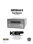
SUPERtrol II
RS-485 Option with
Modbus RTU Protocol
KESSLER-ELLIS PRODUCTS
10 Industrial Way East
Eatontown, NJ 07724
800-631-2165 • 732-935-1320
Fax: 732-935-9344
http://www.kep.com
99640 05/01/12
Introducing SUPERtrol II with RS-485 & Modbus RTU Protocol
When the SUPERtrol II is equipped with the RS-485 communication option, the protocol it uses is the Modbus RTU protocol. This protocol defines a message structure that hosts and clients will recognize and use
on the RS-485 network over which they communicate. It describes the process a master device (PC compatible) uses to request access to another device (SUPERtrol II), how it will respond to requests from the
other devices, and how errors will be detected and reported. It establishes a common format for the layout
and contents of message fields.
During communications on a Modbus RTU network, the protocol determines how each SUPERtrol II will
know its device address, recognize a message addressed to it, determine the kind of action to be taken,
and extract any data or other information contained in the message. If a reply is required, the SUPERtrol II
will construct the reply message and send it using Modbus RTU protocol.
RTU Mode
The SUPERtrol II with RS-485 communications option supports the Modbus RTU (Remote Terminal Unit)
mode only. The Modbus ASCII mode is not supported. The main advantage of the RTU mode is that its
greater character density allows better data throughput than ASCII for the same baud rate. The Modbus
RTU uses a Master-Slave Query-Response Cycle in which the SUPERtrol II is the slave device.
Control Functions
The SUPERtrol II with RS-485 communications option supports the following function codes:
CODE
01
03
05
06
15
16
NAME
Read Coil Status
Read Holding Register
Force Single Coil
Preset Single Register
Force Multiple Coil
DESCRIPTION
Read a single coil
Read a range of holding registers
Forces a single coil (0x reference) to either ON or OFF
Presets a value into a single holding register (4x reference)
Forces each coil (0x reference) in a sequence of coils to either ON
or OFF
Preset Multiple RegistersPresets values into a sequence of holding registers (4x reference)
1
SUPERtrol II RS-485 Port Pinout (recommended mating connector: DB-9M)
1 Ground
2 Ground
3 Ground
RS-232
4 TX/RX (+)
5 TX/RX (-)
1 2 3 4 5 6
6 Do Not Use
7 Terminating Resistor (180 Ω)
8 TX/RX (+) (spare internally connected to 4)
9 TX/RX (-) (spare internally connected to 5)
5 4 3 2 1
9 8 7 6
5 4 3 2 1
9 8 7 6
Phone Line for
Internal Modem
Option
RS-485
1 2
5 4 3 2 1
9 8 7 6
7 8 9 10 11 12 13 14 15 16 17 18 19 20 21 22 23 24
SUPERtrol II RS-485 Port Pinout (Terminal Block Option)
1 Common
2 TX/RX (+)
3 TX/RX (-)
4 Terminating Resistor (180Ω)
RS-232
Phone Line for
Internal Modem
Option
1 2
1 2 3 4
RS-485
5 4 3 2 1
9 8 7 6
1 2 3 4 5 6 7 8 9 10 11 12 13 14 15 16 17 18 19 20 21 22 23 24
Installation Overview
A two wire RS-485 may be multidropped up to 4000 ft. and up to 32 units may be chained together. A RS485 to RS-232 interface adapter is required at the PC. An optically isolated type is recommended. Suitable
wiring should be selected based on anticipated electrical interference. Terminators should be used to help
improve the quality of electronic signals sent over the RS-485 wires. The RS-485 chain should be terminated at the beginning (RS-485 adaptor) and at the last device in the RS-485 chain and nowhere else. On the
SUPERtrol II this is accomplished by connecting a jumper from the terminal labeled Terminating Resistor
(180 Ω) to the terminal labeled TX/RX(+) at the RS-485 port. If lightning protection is required, a suitable
surge protector should be used.
For additional information, refer to the technical requirements of EIA-485, interface adaptor user manual
and the communication software user manual
SUPERtrol II Communication Setup Menu
The setup menu allows Modbus RTU Protocol communications parameters of: Device ID, Baud Rate, and
Parity to be selected to match the parameters of your RS-485 network. Each SUPERtrol II must have it’s
own Device ID and the same Baud Rate and Parity setting.
2
17
18
19
20
21
22
DC (+)
DC (-)
POWER IN
COM RLY3
COM RLY2
NO RLY3
NEMA
12,
1313
Terminal
Designations
NEMA
12.
Terminal
Diagram:
3
Specify Power Input When Ordering.
23 AC LINE
24 AC LINE
NO RLY2
NC RLY2
COM RLY2
TX/RX(+)
Terminating Resistor
(180 ohms)
TX/RX(–)
Common
1
2
3
4
TIP
RING
Not Used
Not Used
Not Used
Not Used
TX
RX
COM
BIAS
DCD
MP (+8 VDC)
1
2
3
4
5
6
1
2
3
4
5
6
RS-485
NO RLY1
COM RLY1
NO RLY2
RS-232
NO RLY1
COM RLY1
NC RLY1
17
18
19
20
21
22
FLOW
IN
TEMPERATURE
IN
Iin (+)
Vin (+)*
Iin (+)
DC OUTPUT
PRESSURE
RTD EXCIT (+)
(TEMP 2)
RTD SENS (+)
IN
Iin (+)
RTD SENS (-)
PULSE OUTPUT (+)
PULSE OUTPUT (-)
ANALOG OUTPUT 1 (+)
ANALOG OUTPUT 2 (+)
ANALOG OUTPUT COMMON (-)
DC OUTPUT
PULSE IN
---------COMMON
RTD EXCIT (+)
RTD SENS (+)
RTD SENS (-)
1
2
3
4
5
6
7
8
9
10
11
12
13
14
15
16
Terminal Layout for Wall Mount Option:
NEMA
12, 13
Layout Layout
NEMA
12.Terminal
13 Terminal
Phone
RATE
147.43 GPM
TOTAL 267395.749 GAL
TOTAL
1
RATE
2
PRE 1
3
TEMP
4
GRAND
6
SCROLL
7
PRE 2
8
DENS
9
PRINT
5
0
TIME
RS-232
RS-485
Phone
1 2 3 4 5 6
1 2 3 4
1 2 3 4 5 6
–
CLEAR
MENU
HELP
•
ENTER
DC Power
3 Relay Option Option
1 2 3 4 5 6 7 8 9 10 11 12 13 14 15 16 17 18 19 20 21 22 23 24
Register & Coil Usage
Register Usage (each register is 2 bytes)
SUPERtrol II Data
Heat Flow
Mass Flow
STD Volume Flow
Volume Flow
Temperature 1
Temperature 2
Delta Temperature
Process Pressure
Diff. Pressure
Density
Specific Enthalpy
Heat Total
Mass Total
STDVolumeTotal
Volume Total
Heat Grand Total
Mass Grand Total
STDVolumeGrandTotal
Volume Grand Total
Alarm Point 1
Alarm Point 2
Alarm Point 3
Year
Month
Day
Hours
Min
Sec
Peak Demand
Demand Last
Viscosity
Abs. Viscosity
Reserved
Power Lost Hour
Power Lost Min.
Reserved
Reserved
Reserved
Reserved
Reserved
Reserved
Reserved
Time base
Heat Flow Units
Mass Flow Units
STD Flow Units
Vol. Flow Units
Temperature Units
Pressure Units
Density Units
Heat Total Units
Mass Total Units
NOTE: The Float data type follows the IEEE format for a 32 bit float.
Register
Reg 40001 & 40002
Reg 40003 & 40004
Reg 40005 & 40006
Reg 40007 & 40008
Reg 40009 & 40010
Reg 40011 & 40012
Reg 40013 & 40014
Reg 40015 & 40016
Reg 40017 & 40018
Reg 40019 & 40020
Reg 40021 & 40022
Reg 40023 & 40024
Reg 40025 & 40026
Reg 40027 & 40028
Reg 40029 & 40030
Reg 40031 & 40032
Reg 40033 & 40034
Reg 40035 & 40036
Reg 40037 & 40038
Reg 40039 & 40040
Reg 40041 & 40042
Reg 40043 & 40044
Reg 40045
Reg 40046
Reg 40047
Reg 40048
Reg 40049
Reg 40050
Reg 40051 & 40052
Reg 40053 & 40054
Reg 40055 & 40056
Reg 40057 & 40058
Reg 40059 & 40060
Reg 40061
Reg 40062
Reg 40063 & 40064
Reg 40065 & 40066
Reg 40067 & 40068
Reg 40069 & 40070
Reg 40071 & 40072
Reg 40073 & 40074
Reg 40075 & 40076
Reg 40077
Reg 40078
Reg 40079
Reg 40080
Reg 40081
Reg 40082
Reg 40083
Reg 40084
Reg 40085
Reg 40086
4
Data Type
Float
Float
Float
Float
Float
Float
Float
Float
Float
Float
Float
Float
Float
Float
Float
Float
Float
Float
Float
Float
Float
Float
Integer
Integer
Integer
Integer
Integer
Integer
Float
Float
Float
Float
Float
Integer
Integer
Float
Float
Float
Float
Float
Float
Float
Integer
Integer
Integer
Integer
Integer
Integer
Integer
Integer
Integer
Integer
Register & Coil Usage (continued)
Register Usage (each register is 2 bytes)
SUPERtrol II Data
STD Total Units
Vol. Total Units
Definition of Barrel
Specific Enthalpy Units
Length Units
Calibration trail Configuration trail
Tag Number
Peak Year Peak Month
Peak Day
Peak Hours
Peak Min
Unused
Unused Unused
Unused
Unused
Unused
Unused
Unused
Unused
Unused
Unused
Unused
Unused
Register
Reg 40087
Reg 40088
Reg 40089
Reg 40090
Reg 40091
Reg 40092
Reg 40093
Reg 40094
Reg 40095
Reg 40096
Reg 40097
Reg 40098
Reg 40099
Reg 40100
Reg 40101 & 40102
Reg 40103 & 40104
Reg 40105 & 40106
Reg 40107 & 40108
Reg 40109 & 40110
Reg 40111 & 40112
Reg 40113 & 40114
Reg 40115 & 40116
Reg 40117 & 40118
Reg 40119 & 40120
Reg 40121 & 40122 Reg 40123 & 40124
Data Type
Integer
Integer
Integer
Integer
Integer
Integer
Integer
Integer
Integer
Integer
Integer
Integer
Integer
Integer
Float
Float
Float
Float
Float
Float
Float
Float
Float
Float
Float
Float
Coil
Coil 00001
Coil 00002
Coil 00003
Coil 00004
Coil 00005
Coil 00006
Coil 00007
Coil 00008
Coil 00009
Coil 00010
Coil 00011
Coil 00012
Coil 00013
Coil 00014
Coil 00015
Coil 00016
Coil 00017
Coil 00018
Coil 00019
Coil 00020
Coil 00021
Coil 00022
Data Type
bit
bit
bit
bit
bit
bit
bit
bit
bit
bit
bit
bit
bit
bit
bit
bit
bit
bit
bit
bit
bit
bit
COIL USAGE (each coil is 1 bit)
SUPERtrol II Data
System Alarm Power Failure
System Alarm Watchdog
System Alarm Communication Error
System Alarm Calibration Error
System Alarm Print Buffer Full
System Alarm Totalizer Error
Sensor/Process Alarm Wet Steam Alarm
Sensor/Process Alarm Off Fluid Table
Sensor/Process Alarm Flow In Over Range
Sensor/Process Alarm Input 1 Over Range
Sensor/Process Alarm Input 2 Over Range
Sensor/Process Alarm Flow Loop Broken
Sensor/Process Alarm Loop 1 Broken
Sensor/Process Alarm Loop 2 Broken
Sensor/Process Alarm RTD 1 Open
Sensor/Process Alarm RTD 1 Short
Sensor/Process Alarm RTD 2 Open
Sensor/Process Alarm RTD 2 Short
Sensor/Process Alarm Pulse Out Overrun
Sensor/Process Alarm Iout 1 Out Of Range
Sensor/Process Alarm Iout 2 Out Of Range
Sensor/Process Alarm Relay 1 Hi Alarm
5
Register & Coil Usage (continued)
COIL USAGE (each coil is 1 bit)
SUPERtrol II Data
Sensor/Process Alarm Relay 1 Lo Alarm
Sensor/Process Alarm Relay 2 Hi Alarm
Sensor/Process Alarm Relay 2 Lo Alarm
Sensor/Process Alarm Relay 3 Hi Alarm
Sensor/Process Alarm Relay 3 Lo Alarm
Service Test 24Vdc Out Error
Service Test Pulse In Error
Service Test Input 1 Vin Error
Service Test Input 1 Iin Error
Service Test Input 2 Iin Error
Service Test Input 2 RTD Error
Service Test Input 3 Iin Error
Service Test Input 3 RTD Error
Service Test Pulse Out Error
Service Test Iout 1 Error
Service Test Iout 2 Error
Service Test Relay 1 Error
Service Test Relay 2 Error
Service Test RS-232 Error
Self Test A/D Malfunction
Self Test Program Error
Self Test Setup Data Lost
Self Test Time Clock Lost
Self Test Display Malfunction
Self Test Ram Malfunction
Language Select
Reset Totalizers
Reset All Error Codes
Reset Alarm 1
Reset Alarm 2
Reset Alarm 3
Print Transaction Document
Reset Peak Demand
Reset Accumulated Power Loss
Aux. Status Input
Reserved
Reserved
Reserved
Reserved
Reserved
Flowmeter Location
Unused
Coil
Coil 00023
Coil 00024
Coil 00025
Coil 00026
Coil 00027
Coil 00028
Coil 00029
Coil 00030
Coil 00031
Coil 00032
Coil 00033
Coil 00034
Coil 00035
Coil 00036
Coil 00037
Coil 00038
Coil 00039
Coil 00040
Coil 00041
Coil 00042
Coil 00043
Coil 00044
Coil 00045
Coil 00046
Coil 00047
Coil 00048
Coil 00049
Coil 00050
Coil 00051
Coil 00052
Coil 00053
Coil 00054
Coil 00055
Coil 00056
Coil 00057
Coil 00058
Coil 00059
Coil 00060
Coil 00061
Coil 00062
Coil 00063
Coil 00064
6
Data Type
bit
bit
bit
bit
bit
bit
bit
bit
bit
bit
bit
bit
bit
bit
bit
bit
bit
bit
bit
bit
bit
bit
bit
bit
bit
bit Write
bit Write with Caution
bit Write
bit Write
bit Write
bit Write
bit Write
bit Write
bit Write
bit
bit
bit
bit
bit
bit
bit
bit