1
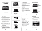
Usage of SV 102 and SV 102A
Noise Dosimeters with
SV 25S Microphone
in Real Ear Technique (MIRE)
Short User Guide
Warsaw, March 2011
SV 25S Short User Guide
Please read the whole user guide before
assembling the SV 25S microphone kit
IT IS VERY IMPORTANT.
Table of Contents:
1. Introduction ........................................................................................ 3
2. Elements of the SV 25S set…….…………………………….………….4
3. Assembling of the SV 25S microphone .............................................. 5
4. Calibration of SV 25S microphone…. ................................................. 8
5. Using SV 25S microphone…. ............................................................. 9
2
SV 25S Short User Guide
1. Introduction.
Microphone In Real Ear (MIRE) is a technique for assessing the noise sources
placed in a short distance to a human ear.
SV 25S microphone measures
sound pressure level in the ear
canal by means of the probe which
is placed at the entry to the ear
canal. The length of the probe is
16mm to ensure the maximum
comfort and protect from contact
with the eardrum.
To prevent any damage of the
eardrum or skin and ensure the
hygienic comfort, the probe tube is
covered by disposable silica pipe.
SV 25S is dedicated to be used with SV 102 and SV 102A Noise Dosimeters.
For usage of SV 25S microphone the appropriate digital correction filter is required.
For this reason, the SV 25S cannot be used with any other SLM than SV 102 or
SV 102A.
Microphone must be connected to the SV 102 (or SV 102A) instrument in the first
turn! After this step instrument can be switched on.
SV 102 instrument automatically detects type of microphones connected and
activates the appropriate compensation filters.
Because historically SV 25S microphone was used with different length probes
ensure that the appropriate probe length is selected in the instrument’s menu.
Depending on this setting the adequate compensation filter is activated!
In order to choose the appropriate compensation
filter, user has to select the PROBES length in
the menu SETUP\MIRE and press the <ENTER>.
Instrument
detects
SV 25S
automatically
signalizing it in menu SETUP\MIRE as ON/OFF
3
SV 25S Short User Guide
2. Elements of the complete set: SV 25S and SA131 calibration
adapter.
SV 25S complete set consists of following elements:
A. Microphone housing (2 pieces – one spare part)
B. O-ring (2 pieces- one spare part)
C. Silica pipe for the yellow probe (SA125 16mm), in standard there is one pack
containing 45 pieces
D. Yellow probe (SA25S 16mm), in standard 2 pieces are delivered (one spare
part)
E. Calibration adapter SA131 (optional)
F. Over-ear microphone
4
SV 25S Short User Guide
3. Assembling of the SV 25S microphone.
Microphone SV 25S is not a ready-to-use product. This fact is caused by necessity of
adopting the microphone to the individual ear features of person who is going to wear
the microphone.
To assemble the SV 25S microphone user must follow four steps:
Step one: dismount the microphone housing (element A) from the over-ear
microphone (K).
Step two: place the microphone probe (D/F) on the connector making sure that one
o-ring (B) is placed between probe and connector. In a new set the o-ring is already
mounted on the connector.
O-ring is installed
on the probe
connector
5
SV 25S Short User Guide
Use the spare o-ring only in case the original one is not placed on the connector:
Step three: mount the microphone housing (A) on the probe putting the probe
through the hole on the top of element A.
6
SV 25S Short User Guide
Step four: connect the ending of
the over-ear microphone to the side hole of
element A.
7
SV 25S Short User Guide
4. Calibration of the SV 25S microphone with SV30/SV31 acoustic
calibrator.
SA 131 adapter is required to calibrate SV 25S with ½” acoustic calibrator. Place the
SV 25S probe inside the calibration adapter and then put them inside the acoustic
calibrator.
IMPORTANT NOTE!!
Sound pressure generated by calibrators other than SV 30A & SV 31 at the SV 25S microphone
may vary from the nominal level of the calibrator because of different air volume comparing to
classic 1/2” microphones.
Therefore a correction is necessary for some calibrators:
SV 30A correction is not necessary (0.0dB)
SV 31 correction is not necessary (0.0dB)
SV 32 correction factor equals to (-0.15dB)
Correction factor must be added to the nominal level of the calibrator indicated in calibration
certificate of the calibrator.
Example:
Suppose SV 32 calibration level is 94.1dB.
The calibration level that suppose to be typed in during calibration of SV102 is 93.95dB
Calibration procedure of the instrument is described in
Chapter 5 of SV 102 User Manual
8
SV 25S Short User Guide
5. Using the SV25S microphone.
Before placing the SV 25S microphone in the ear
remember to put the silica pipe on the probe.
Color and length of silica pipe should match the probe’s.
When calibration process is finished SV 25S is ready to use. Pictures show the
correct placing of the microphone on the human’s ear:
Take caution whenever the microphone is placed inside the human ear. Correct
position for probe placement is the entry of the ear channel not inside of it!
Otherwise sudden movements of the user or unexpected blows around ear area
may cause serious injuries if enough carefulness is not kept.
9