1
6700/8700 TRAINING - LEVEL III
March 10th 1997
Rev. 1.0
*60
75$,1,1*/(9(/,,,
1
High Tech. Centre - Flensburg
European Cellular Subscriber Division
Author: Michael Hansen / Technical Support
6700/8700 TRAINING - LEVEL III
March 10th 1997
Rev. 1.0
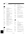
1 GENERAL
3
1.1 HW / SW
3
1.2 IC‘s
3
1.3 Frequency‘s
3
2 POINTS TO NOTE
4
2.1 Backhousing
4
2.2 Fronthousing
4
2.3 Main PCB
4
3 TOP XX FAILURE
5
3.1 Main PCB
5
3.2 Display PCB 6700
5
3.3 Display PCB 8700
5
2
High Tech. Centre - Flensburg
European Cellular Subscriber Division
Author: Michael Hansen / Technical Support
6700/8700 TRAINING - LEVEL III
1
March 10th 1997
Rev. 1.0
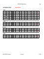
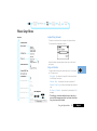
GENERAL
1.1 HW / SW
Prod.
SW / HW
Version
Part.No
6700
3.6 / 1.3
78.63.23
SUF3997C
8700
3.6 /1.3
74.05.22
SUF3839G
1.2 IC‘s
Prefix / Name
Version
Note
Part.No
U703 / BIC
4.01
incl. AD / DA converter
5109743E13
U801 / SPC
11.80
AT&T
5199285C01
U501 / Modem
35.xx / 40.xx
5109632D42 / D49
U701 / Proc.
68338
5113802M40
U201 / GIF_SYN
--.--
IF / GUSS in one hsng.
5109632D64
U702 / SW
xxxx
with / without
boot sector
5199245C30 / A01
U900 / GCAP
--.--
0109632D73
1.3 Frequency‘s
Location
Frequency ( CH62 )
TX
902.4 MHz
RX
947.4 MHz
Ref. Osc.
Note
13.0 MHz
Main VCO
794.4 MHz
TX Offset L-Osc.
216.0 MHz
Internal GIF_SYN - 108 MHz
RX L-Osc.
306.0 MHz
Internal GIF_SYN - 153 MHz
3
High Tech. Centre - Flensburg
European Cellular Subscriber Division
Author: Michael Hansen / Technical Support
6700/8700 TRAINING - LEVEL III
March 10th 1997
Rev. 1.0
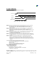
2 Points to Note
2.1 Backhousing
Be sure that the pad against vibration from T900 is mounted.
2.2 Fronthousing
Be sure that the GND pads are in the right position. ( especially close to the antenna ).
Sometimes they are not in right position and make shortages to the antenna switch. (No TX )
Sometimes the vibra is not in the right position. (it makes some noise to the housing )
If the housing got twisted sometimes the loudspeaker makes bad noise.
Be sure that the alert has the right polarisation.
2.3 Main PCB
The first revision of 8700 were built with two types of displays C04 / C05. Both types
have there own programming in the EE prom of the main board. If you want to use another
type of display you have to send the main PCB to the responsible national HUB support or to
the HTC for reprogramming the EE-Prom.
Follow DB034 to do the GCAP-Fix. (( only up to and incl. print rev. r09 )( Four changes on
main PCB 6700 /8700 and two changes on the display board 6700),( only up to and incl.
print rev. r09 )) additional you have to remove C905 up to and incl. print rev. R13.
If you remove or replace a shield be sure that the shield is mounted in the right direction.
4
High Tech. Centre - Flensburg
European Cellular Subscriber Division
Author: Michael Hansen / Technical Support
6700/8700 TRAINING - LEVEL III
March 10th 1997
Rev. 1.0
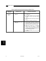
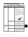
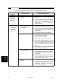
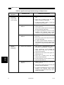
3 Top XX Failure
3.1 Main PCB
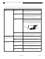
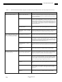
Bad RX / TX.
>>>
caused by a shortage between L304 and
the shielding ( first shield on the RF
side close to the antenna A1 ) done by
replacing the shield by service or
mounting by production.
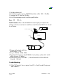
The radio turns off after seconds.
>>>
Y 201 is defective.
If you replace the crystal to another
type [ e.g. J04
, to J07 ]
you have to change also the
capacitor C203.
>>>
>>>
Y201 4809813J04 - C203 2113740F41
Y201 4809813J07 - C203 2113740F49
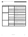
The radio doesn’t turn on.
>>>
GCAP defective caused by not done fix.
------------------------------------------
>>>
VR 604 is defective. Often together
with the GCAP.
The radio turns off after seconds or
minutes.
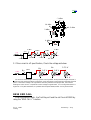
>>>
in the first revision C831, C901,C906
and C916 (orange cap.) are sometimes
placed in the wrong direction.
No automatically audio switching in
DHFA to HF mode.
>>>
In print revision r03 up to and include
r05 is a wire fix in the DSC_EN_B line
with sometimes bad soldering.
T900 mechanical defective.
3.2 Display PCB 6700
Failures are unknown.
3.3 Display PCB 8700
Failures are unknown.
5
High Tech. Centre - Flensburg
European Cellular Subscriber Division
Author: Michael Hansen / Technical Support
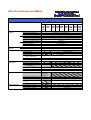
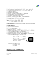
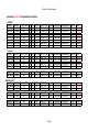
MicroTac Accessories Matrix
Compatibily Matrix
MicroTAC
Part Numbers to order
5200/
7200
GSM
900
Normal
Batteries
7500
GSM
900
6200 8200 8400 8700 d400 Flare
GSM GSM GSM GSM Series GSM
900
900
900
900 GSM 1800
900
Lilon 400mAh Slim Battery
(SNN4554) - E*P Charger Only
100mAh Slim XCap Battery
(SNN4697) - E*P Charger Only
1200mAh XCap Battery
64615 (SNN4458) - E*P Charger Only
NiMh 600mAh XSlim Battery
64620 (SNN4612)
750mAh Slim XCap Battery
64621 (SNN4310)
1300mAh XCap Battery
64619 (SNN4259)
1600mAh High Capacity Battery
(SNN4824)
NiCd 400mAh Slim Battery
64618 (SNN4132)
600mAh Slim Battery
64630 (SNN4102)
1100mAh XCap Battery
64617 (SNN4058)
Batteries
NiCd 400mAh XSlim Battery w/clip
(SNN4564)
with Clip
NiMh 600mAh XSlim Battery w/clip
(SNN4887)
Chargers
E*P Charger Base
64606 (SPN4462)
E*P Euro adaptor
64604 (SPN4222)
E*P UK adaptor
64605 (SPN4221)
Overnight Charger
(S6334)
Base & Transformer
IntelliCharger XT w/Euro
64608 (SPN4463 + SPN4112) - Non Lilon compatible
IntelliCharger XT w/UK
64609 (SPN4463 + SPN4111) - Non Lilon compatible
In-Car
Battery Saver
6407(SKN4292)
Accessories
Ultra Saver (no RF connection)
64610 (SLN9933)
Ultra Saver with RF connection (SLN9934)
for 8000/Flare
Phone Cradle
64629 (SYN4932 + TRN5502)
Headset + Adapter
Available soon
Professional Charger Car Kit
(S3060)
Car Kits
Basic Car Kit 7000
64628(SKN4292
,SYN4932,
TRN5502)
Basic Car Kit 8000/c400 Series
64627 (SLN9934 + SYN4932 + TRN5502)
Professional Hands-free Car Kit
(S5619)
Professional DSP Hands-free
Available soon
Car Kit
User install Hands-free Car Kit
Available soon
Carry Accessories
Executiv Holster - Leather
64613(SLN8500)
Executiv Holster - Leather
(SYN6198)
Sports Holster - Synthetic
(SYN6457)
c400
Series
GSM
1800
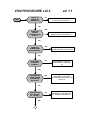
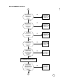
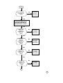
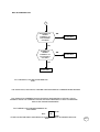
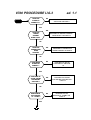
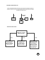
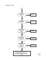
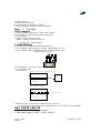
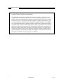
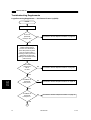
8700 PROCEDURE LVL3
START
DOES PCB
POWER UP
CORRECTLY.?
NO
ed. 1.1
PROCEED TO "WILL NOT POWERS
& STAY ON" ON PAGE 3
YES
YES
DOES PCB
DRAWS
CURRENT WHEN
IS OFF?
PROCEED TO "DRAWS CURRENT
WHEN IS OFF" ON PAGE 19
NO
DOES PCB
POWER DOWN
WHEN TWISTED?
YES
PROCEED TO "POWER OFF
WHEN TWISTED" ON PAGE 8
NO
DOES WAKE
UP DISPLAY
CORRECT.?
NO
PROCEED TO "NO OR
LOW DISPLAY" ON PAGE
18
YES
PROCEED TO "PHONE
FAILURE SEE SUPPLIER" ON
PAGE 19
YES
DOES DISPLAY
SHOW "PHONE
FAILURE SEE
SUPPLIER"?
NO
DOES PCB GO
INTO SERVICE
AT -102dBm?
YES
1
NO
PROCEED TO "NO SERVICE
AT -102dBm" ON PAGE 12
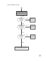
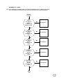
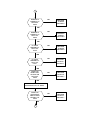
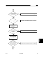
1
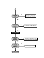
CAN PCB
INITIATE A
CALL TO THE
ANALYZER?
NO
PROCEED TO "WILL NOT
INITIATE A CALL" ON PAGE 9
YES
TERMINATE THE CALL
CALL MOBILE FROM
ANALYZER
IS RING AUDIO
TONE AUDIBILE?
NO
PROCEED TO "NO OR LOW
RING TONE" ON PAGE 1
YES
ANSWER CALL.
IS THE TX FREQ
OR PHASE ERROR
WITHIN SPEC.?
NO
PROCEED TO "FREQ ERR." OR
"PHASE ERROR OUT OF
YES
IS THE POWER
BURST WITHIN
SPEC.?
YES
2
NO
PROCEED TO "POWER BURST
OUT OF SPEC." ON PAGE 17
2
IS THE TX
AUDIO PATH
OK.?
NO
PROCEED TO "NO OR LOW
AUDIO VOLUME" ON PAGE 1
YES
IS AUDIO
LOOP-BACK
CORRECT.?
NO
PROCEED TO "NO OR LOW AUDIO
MICROPHONE" ON PAGE 2
YES
TERMINATE THE CALL
IS THE LOW
BATTERY
INDICATION
CORRECT.?
NO
PROCEED TO "INCORRECT LOW
BATTERY INDICATION"ON PAGE 18
YES
NO
DOES THE
CHARGER
FUNCTION
CORRECTLY?
YES
NO FAULT FOUND
PROCEED TO "NO CHARGER"
ON PAGE 20
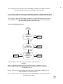
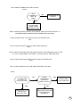
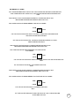
NO OR LOW RING TONE
START
IS THE SIGNAL
CORRECT AT
PIN 4 OF U803?
NO
RT 1
YES
RT 3
YES
IS THE SIGNAL
CORRECT AT
PIN 4 OF U900
NO
RT 2
RT1: CHECK IF U801 IS POSITIONED CORRECTLY OR BAD SOLDER, IF ANY
MENTIONED PROBLEM ARE PRESENT REPLACE U801
RT2: CHECK IF U802 AND U803 ARE POSITIONED CORRECTLY OR BAD SOLDER
ALSO CHECK C825,C817 AND R803. IF ANY MENTIONED PROBLEM ARE PRESENT
REPLACE U803
RT3: CHECK IF U900 IS POSITIONED CORRECTLY OR BAD SOLDER AT PIN
4.5.6.7, CHECK ALSO PIN CONNECTOR 5.7 OF J2. IF ANY MENTIONED
PROBLEM ARE PRESENT REPLACE U900.
NO OR LOW AUDIO VOLUME
START
IS SIGNAL
CORRECT AT
PIN 4 OF U803?
NO
AV1
TX3: CHE
CORRECT
YES
YES
AV3
IS SIGNAL
CORRECT AT
PIN 21 OF
U900?
NO
AV2
IF THE CO
P1
TX5: TAKES
AV1: CHECK IF U801 AND U803 ARE POSITIONED CORRECTLY OR BAD SOLDER IF
ANY MENTIONED PROBLEM ARE PRESENT REPLACE U803.
AV2: CHECK IFU802 AND U803 ARE POSITIONED CORRECTLY OR BAD SOLDER, ALSO
CHECK C825 AND R810. IF ANY MENTIONED PROBLEM ARE PRESENT REPLACE U803.
AV3: CHECK IF U900 IS POSITIONED CORRECTLY OR BAD SOLDER AT PIN 19.20.21,
PIN CONNECTOR 22.20 OF J2 AND R802,R810,C804 AND C825. IF ANY MENTIONED
PROBLEM ARE PRESENT REPLACE U900.
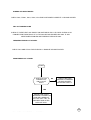
NO OR LOW AUDIO MICROPHONE
START
IS AUDIO
CORRECT ON
PIN 10 OF
U900?
NO
MIC 01
YES
IS AUDIO
CORRECTON
PIN 17 OFU803?
NO
MIC02
YES
MIC 04
YES
IS AUDIO
DIGITAL
CORRECT ON
PIN 84 OF
U801?
NO
MIC 03
MIC 01: CHECK J802, C810, C813, C808, R806, R805 FOR BAD
SOLDER.
MIC02: CHECK VOLTAGE ON PIN 17/18/19/20 OF U803, IS ABOUT 2.4V, IF IS
NOT CORRECT REPLACE C832 AND C848; IF IS CORRECT CHECK U900 AND
AFTER REPLACE IT.
MIC 03: CHECK IF U803 AND R838, R842, R841 ARE POSITIONED CORRECTLY OR
BAD SOLDER AFTER REPLACE U803.
MIC 04: CHECK IF U801 AND R845 ARE POSITIONED CORRECTLY OR BAD SOLDER
AFTER REPLACE U801.
P2
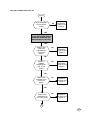
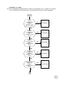
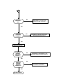
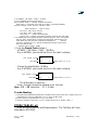
WILL NOT POWERS UP & STAY ON
START
IS B+ PRESENT
AT PIN 48 OF
U900?
NO
PROCEED
TO NPU1 ON
PAGE 6
YES
TIE THE WATCHDOG HIGH BY
SHORTING TOGETHER THE
WATCHDOG PULL UP PADS.
YES
DOES 3.25V
VSWITCH
CORRECTAT
PIN 25 OF
U900?
NO
PROCEED
TO NPU2 ON
PAGE 6
YES
DOES LX
300KHz
PRESENT AT
PIN 37 OF
U900?
NO
PROCEED
TO NPU3 ON
PAGE 6
YES
DOES L275
CORRECT AT
PIN 22 OF
U900?
NO
PROCEED
TO NPU5 ON
PAGE 6
YES
NO
DOES L500
CORRECT AT
PIN 3 OF U900?
PROCEED
TO NPU4 ON
PAGE 6
1
P3
WILL NOT POWERS UP & STAY ON
SET THE C
PUT T
1
DOES R275
CORRECT AT
PIN 28 OF
U900?
NO
PROCEED
TO NPU6 ON
PAGE 6
YES
DOES R475
CORRECT AT
PIN 41 OF
U900?
NO
PROCEED
TO NPU7 ON
PAGE 6
YES
IS 13MHz
PRESENT AT
PIN 37 OF
U703?
NO
PROCEED
TO NPU8 ON
PAGE 6
YES
IS 13MHz
PRESENT AT
PIN 51 OF
U701?
NO
PROCEED
TO NPU9 ON
PAGE 7
YES
DOES THE
RESET LINE
GO HIGH ON
PIN 30 OF
U900?
NO
PROCEED
TO NPU10
ON PAGE 7
NO
PROCEED
TO NPU11
ON PAGE 7
YES
REMOVE SHORT ON
WATCHDOG PULL UP PADS
DOES THE
WATCHDOG
LINE GO HIGH
ON PIN 31 OF
U900?
YES
2
P4
WILL NOT POWERS UP & STAY ON
WILL NOT POWERS UP & STAY ON
2
TIE THE WATCHDOG HIGH BY
SHORTING TOGETHER THE
WATCHDOG PULL UP PADS.
YES
IS THE
NO CE
PRESENT ON
PIN 26 OF
U702?
NO
PROCEED
TO NPU12
ON PAGE 7
YES
IS THE CE
NO ON
PRESENT
PIN 39 AND 40
OF U704?
NO
PROCEED
TO NPU13
ON PAGE 7
YES
IS THE CE
NO ON
PRESENT
PIN 27 OF
U705?
NO
PROCEED
TO NPU14
ON PAGE 7
YES
TRY TO RESOLDER FLASH-PROM
U702 AND AFTER REPLACE IT.
P5
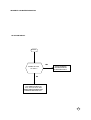
NPU1:CHECK CONNECTOR J400 FOR DRY
JOINT.
IS B+
PRESENT AT
PIN 1 OF
Q999?
NO
RETURN PCB TO
HI-TECH.
YES
CHECK POLARITY
OF C907 AND
CR998. AFTER
REPLACE CR 998.
NPU2: CHECK SOLDER ON U900. ALSO CHECK T900 FOR SHORT CIRCUIT. IF
ANY MENTIONED PROBLEM ARE PRESENT REPLACE U900.
NPU3: CHECK CR910 C916 FOR POLARITY AFTER REPLACE
T900.
NPU4: CHECK POLARITY OF C901 AND AFTER REPLACE
U900.
NPU5: CHECK C902 AND C903 FOR SHOR CIRCUIT AFTER REMOVE U900, IF THE
S.C. STILL AGAIN SENT TO HI-TECH ; IF IS NOT ON S.C. REPLACE U900.
NPU6: CHECK C908 FOR SHORT CIRCUIT AND AFTER REPLACE
U900.
NPU7: CHECK POLARITY OF C906 AND AFTER REPLACE U900.
NPU8:
IS 13 MHz CKIN
PRESENT ON
PIN 17 OF U703?
YES
CHECK R714, C701
AND AFTER
REPLACE U703.
NO
CHECK
VOLTAGE ON
Q203 AND
Q202, IS 2.75V?
YES
CHECK CR201,
Y201 AND U201
NO
CHECK C212, C214 AND
AFTER REPLACE
Q202/Q203.
P6
NPU9: CHECK TRACK FROM R714 TO PIN 51 OF U701.
NPU10: CHECK SOLDER ON U900, TRY TO RESOLDER U702
OR CONNECT RADIO TO THE EMMIBOX FOR UPGRADE.
NPU11: CHECK WATCHDOG LINE FROM PIN 31 OF U900 TO R741/PIN 56 OF U703, AND FROM
PIN 31 OF U900 TO PIN 60 OF U701. IF ANY MENTIONED PROBLEM ARE PRESENT REPLACE
U900.
NPU12: U701 BEING SENT CE TO U704. CONTROL CE LINE FROM PIN 100 OF U701 TO PIN 26
OF U702, IF IS CORRECT REPLACE U702.
NPU13: U701 BEING SENT CE FROM PIN 102 TO PIN 40 OF U704. IF IS CORRECT REPLACE
U704.
NPU14: U701 BEING SENT CE FROM PIN 114 TO PIN 27 OF U705 TRY TO
CONNECT RADIO TO THE EMMIBOX FOR UPGRADE THE RADIO.
P7
POWERS OFF WHEN TWISTED
CHECK Y201, CR201, U201, U702, U704 FOR POSITIONED CORRECTLY OR BAD SOLDER
WILL NOT POWERS DOWN
CHECK IF THERE ISN'T ANY SHORT ON WATCHDOG PULL UP PADS. CHECK ALSO
CONNECTION FROM PIN 25 OF J2 TO R990 OR BAD SOLDER ON U900. IF ANY
MENTIONED PROBLEM ARE PRESENT REPLACE U900.
FREQUENCY ERROR OUT OF SPEC.
CHECK Y201 AND CR 201 FOR PHISICALLY DAMAGE OR BAD SOLDER.
PHASE ERROR OUT OF SPEC.
START
ARE TXI & TXQ
CORRECT AT
PIN 61.63 OF
U201?
NO
CHECK U501 FOR
PHISICALLY DAMAGE
OR BAD SOLDER,
AFTER REPLACE IT.
YES
CHECK FOR RIGTH
FREQUENCY 216MHz ON
C228 AND 108MHz AT
PIN 4 OF U201. TRY TO
REPHASE AND AFTER
REPLACE U201.
P8
NPU1:CHECK CONNECTOR J400 FOR DRY
JOINT.
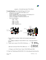
WILL NOT INITIATE A CALL
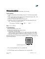
CONNECT 50 OHM LOAD TO THE ANTENNA PLUG, PUT THE RADIO IN TEST MODE AND SET TX CHECK PIN
POWER IN CONTINIOUS MODE OR IMPULSIVE MODE LIKE FOLLOWING INSTRUCTION:
REPHAS
IMPULSIVE
11062# 1200#
310#
CONTINUOS
11062# 1215# 40#
START
IS 902.4MHz TX
SIGNAL
CORRECT AT
TX1 PIN 8 OF
U400?
YES
TX REPAIR 1
NO
IS 902.4MHz TX
SIGNAL
CORRECT AT
TX2 ON L302?
YES
TX REPAIR 2
NO
IS 902.4MHz TX
SIGNAL
CORRECT AT TX
3 BASE OF
Q302?
YES
TX REPAIR 3
NO
IS 902.4MHz TX
SIGNAL
CORRECT AT
TX4 ON BASE OF
Q381
YES
TX REPAIR 4
NO
1
P9
WILL NOT INITIATE A CALL
1
IS 902.4MHz TX
SIGNAL
CORRECT AT
TX5 ON BASE OF
Q300?
YES
TX REPAIR 5
NO
IS108MHz IF
SIGNAL
CORRECT AT
TX 6 ON PIN 4
OF U300?
YES
TX REPAIR 6
NO
TX REPAIR 7
TX1: CHECKC442, L433 AND AFTER REPLACE
U400
TX2: CHECK C439, L302.303.304, C328 AND C329 FOR PHISICALLY DAMAGE OR BAD SOLDER.
TX3: CHECK IF B+ IS PRESENT ON COLLECTOR OF Q302 AND PIN 2.3 OF Q301. IF B+ IS
CORRECT TRACE THE TX SIGNAL TROUGH THE PATH FROM Q302 TO Q301 TO DECIPHER
WICH IS THE FAILURE COMPONENT.
TX4: TAKES DC VOLTAGE MEASUREMENT AS
FOLLOWING:
B+ C
E 0.3V
Q 381
B 0.5V
IF THE COLLECTOR IS NOT SUPPLIED BY B+ CHANGE L380. IF B+ IS CORRECT REPLACE
P10
Q381.
TX5: TAKES DC MEASUREMENT VOLTAGE AS FOLLOWING:
WILL NOT INITIATE A CALL
1.2V B
Q 300
C 2.7V
0.6V E
IF THE COLLECTOR IS NOT SUPLLIED BY 2.7V CHECK C 301.302.325. IF 2.7V ON
COLLECTOR IS OK CHECK C 304.314.381 R352 AND AFTER REPLACE Q300.
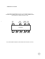
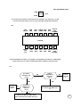
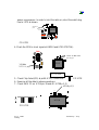
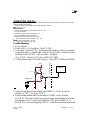
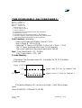
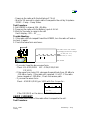
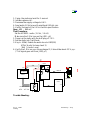
TX6:
PIN7
DM_CS
PIN6
GND
PIN5
GND
6
5
7
PIN4 IF PIN3
108MHz GND
4
PIN2
R275
PIN1 TX
VCO
796.4MHz
3
2
1
12
13
14
U 300 TIC
8
9
PIN8 CP
OUT 2.1V
PIN9
R475
10
11
PIN10
R475
PIN11 PIN12 PIN13 PIN14 RX
GND R275 GND
VCO
902.4MHz
CHECK PRESENCE OF SIGAL FOLLOWING THE SCHEMATIC AS ABOVE TO DECIPHER
WICH IS THE FAULTY LINE. IF EVERITHINGS ARE CORRECT REPLACE U300.
TX7:
IS 216MHz
PRESENT ON
C228?
NO
YES
REPLACE
Q203
NO
IS RX 2.75V
PRESENT AT
PIN 3 OF
U201?
IS R475
PRESENT AT
PIN 44 OF
U201?
NO
CHECK
U900 PIN
41.
YES
CHECK FOR BAD SOLDER
U201 AND AFTER REPLACE
IT.
YES
CHECK FOR BAD SOLDER CR203,
L203.AFTER REPLACE REPLACE U201
P11
NO SERVICE AT -102dBm
SET THE COMMUNICATIONANALYZER TO INJECT VIA ANTENNA PLUG -30dBm AT 947.4MHz,
PUT THE RADIO IN TEST MODE AND LOAD SYNTHETIZER WITH 33062# COMMAND.
START
IS RX1
947.4MHz RX
SIGNAL
CORRECT ON
PIN 5 OF U400?
NO
RX REPAIR 1
YES
IS RX2
947.4MHz RX
SIGNAL
CORRECT ON
C407?
NO
RX REPAIR 2
YES
IS RX3
947.4MHz RX
SIGNAL
CORRECT ON
C408?
NO
RX REPAIR 3
YES
IS RX4
947.4MHz RX
SIGNAL
CORRECT ON
C409?
NO
RX REPAIR 4
YES
IS RX4 794.4
MHz VCO
SIGNAL
CORRECT ON
C409?
NO
VCO REPAIR
YES
1
P12
NO SERVICE AT -102dBm
1
IS RX5 153MHz
CORRECT ON
R426?
NO
RX REPAIR 5
YES
IS RX6 153MHz
CORRECT ON
C421?
NO
RX REPAIR 6
YES
IS RX7 153MHz
CORRECT ON
PIN 31 OF U201?
NO
RX REPAIR 7
YES
ARE RXI AND
RXQ CORRECT
AT PIN 14 AND
15 OF U501?
NO
RX REPAIR 8
YES
ARE THE SPI
ACTIVITY
PRESENT AT
PIN 4, 6 AND 8
OF U501?
NO
RX REPAIR 9
YES
TRY TO REPHASE VIA GATE 22, IF STILL NO
FUNCTION CHANGE U501. IF ANY
MENTIONED ACTION RESOLVE THE
PROBLEM RETURN PCB TO HI-TECH
CENTRE.
P13
NO SERVICE AT -102dBm
RX1: FROM ANTENNA PORT CHECK L439, C440 FOR BAD SOLDER AND AFTER REPLACE
U400. FROM SWITCH RF CHECK L443, C442 FOR BAD SOLDER AND AFTER REPLACE U400.
RX2:CHECK IF FL451 IS POSITIONED CORRECTLY OR BAD SOLDER. IF ANY
MENTIONED PROBLEM ARE PRESENT REPLACE FL451.
RX3:TAKES ON Q418 DC MEASUREMENT LIKE AS FOLLOWING:
1.3V B
Q 418 C 2.7V
0.5V E
# IF THE COLLECTOR IS NOT SUPLLY BY RX275, CHECK Q203 AND ASSOCIATE
CIRCUITRY.AFTER REPLACE Q203.
# IF THE COLLECTOR IS SUPLLY BY RX275 FROM Q203 CHECK L412, R432
AND AFTER REPLACE Q418.
RX4:CHECK FL452 FOR PHICALLY DAMAGE OR BAD SOLDER. IF ANY
MENTIONED PROBLEM ARE PRESENT REPLACE FL452.
RX5: TAKES ON Q420 DC MEASUREMENT VOLTAGE LIKE AS
FOLLOWING:
1V B
Q 420 C 2.7V
0.37 E
# IF THE COLLECTOR IS NOT SUPPLY BY RX275, CHECK L414 AND AFTER REPLACE
Q203.
# IF THE COLLECTOR SUPLLY IS CORRECT REPLACE
Q420.
RX6:CHECK FL420 IF IS NOT PHISICALLY DAMAGE OR BAD SOLDER. IF ANY
MENTIONED PROBLEM ARE PRESENT REPLACE FL420.
RX7:TAKES ON Q421 DC MEASUREMENT VOLTAGE LIKE AS FOLLOWING:
0V B
Q 421 C 1.9V
0.6V E
# IF THE COLLECTOR SUPPLY IS CORRECT REPLACE
Q421.
# IF THE COLLECTOR IS NOT SUPPLY BY PIN 33 OF U201, CHECK R423 AND
AFTER REPLACE U201.
P14
RX:8
START
IS RX LOCAL
OSC. 306MHz
PRESENT ON
PIN 39 OF
U201?
NO
RX LOCAL OSC.1
YES
RX LOCAL OSC.2
RX9:IF THERE IS NOT ACTIVITY ON SPI BUS TRY TO REPHASE AND AFTER REPLACE
U501.
RX LOCAL OSC.1:CHECK FOR CR431, L433 AND U201 PHISICALLY DAMAGE OR BAD
SOLDER. IF ANY MENTIONED PROBLEM ARE PRESENT REPLACE U201.
RX LOCAL OSC.2:CHECK IQ_ REF FROM PIN 16 OF U501 TO PIN47 OF U201, 1.38V IS
CORRECT CONTROL FROM MODEM.
# IF THE CONTROL IS CORRECT CHANGE U201.
# IF THE CONTROL IS NOT CORRECT, TRY TO REPHASE AND AFTER REPLACE
U501.
P15
VCO REPAIR:
START
IS VCO
794.4MHz
CORRECT AT
PIN 4 OF
FL453?
YES
VCO REPAIR 1
NO
IS 2.5V VCO
SUPPLY
CORRECT
FROM PIN 21
OF U201?
NO
VCO REPAIR 2.
YES
RETUR PCB TO
HI-TECH.
VCO REPAIR 1:CHECK IF FL453 IS NOT PHISICALLY DAMAGE OR BAD SOLDER. IF ANY
MENTIONED PROBLEM ARE PRESENT REPLACE FL453.
VCO REPAIR 2:CHECK SUPPLIES FROM Q203 AND Q202. IF THEY ARE INCORRECT TAKES
REFERENCE FROM A FULLY FUNCTIONALLY PCB TO DECIPHER WHICH COMPONENTS
CAUSES NO OR POOR SUPER FILTER SUPPLY FOR VCO.POSSIBLE DEFECTIVE
COMPONENTS ARE Q202, Q203,C212,C214 AND U201.
P16
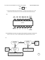
POWER BURST OUT OF SPEC.
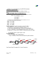
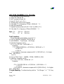
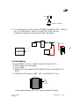
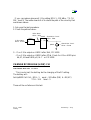
FOLLOWING THE SCHEMATIC OF PAC_IC U310 CHECK THE PIN 7 (PA
CONTROL) IF IS CORRECT REPLACE Q301, Q302. IF IS NOT CORRECT CHECK
THE OTHER PIN TO TRACE THE FAULTY LINE.
TO PIN 26
PIN7
EXC.
PIN4
PAC_ENI
PIN2 RF
SAT_DET
7
4
2
PIN1
GND
1
U 310 PAC IC
8.9
10
11
PIN9
AOC
PIN10
TX_KEY
PIN11
DET__SW
12
14
PIN12
PIN14
SAT_DET PAC_ENI
IF ANY MENTIONED PROBLEMS ARE PRESENT RETURN PCB TO HI-TECH.
P17
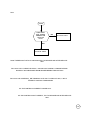
INCORRECT LOW BATTERY INDICATION
AND SET TX CHECK PIN 46 AND 47 OF U901 FOR CORRECT INDICATION TO U703 PIN 4 AND 64.TRY TO
UCTION:
REPHASE (MASTER CARD AND AFTER GATE 22) AND IF ANYTHING CHANGE REPLACE
U703.
NO OR LOW DISPLAY
START
YES
IS PIN 4 OF U101
AT -9.6V ?
CHECK FOR BAD
SOLDER ON Q102
AFTER REPLACE IT.
NO
CHECK L500 ON PIN 6 OF
U101 AND POLARITY OF
C101, C102, C103. IF ANY
MENTIONED PROBLEM ARE
PRESENT REPLACE U101.
P18
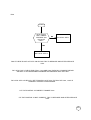
PCB DRAWS CURRENT WHEN IS OFF
CHECK TRANSISTOR REGULATOR: Q202, Q203 AND U201 ARE NOT PHISCALLY DAMAGE;
CHECK ALSO U900 TO MONITORING WHICH COMPONENT BECOMING WARMER AFTER
REPLACE IT.
VREF. FROM
U900
B+
P.A. MOD.
Q301.302
Q202
U201
B+
U900
2.75V
Q203
2.75V
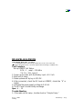
PHONE FAILED SEE SUPPLIER
ENTER 7100# , 7101# AND
REPORT THE CODES
04/XX
CHECK Q203 FOR RX
275: IF IS NOT
CORRECT REPLACE
Q203; IF IS CORRECT
REPLACE U501.
07/XX
TRY TO REFLEX U702
VIA EMMIBOX OR
MASTER CARD IF
STILL NOT CORRECT
SEND TO HI-TECH.
05/XX
ENTER 171# AND 57#
AND POWER UP THE
RADIO AGAIN. IF STILL
NOT CORRECT CHECK
FOR 26 MHz FROM PIN
6 OF U805: IF IS OK
REPLACE U801, IF IS
NOT OK REPLACE
U805.
P19
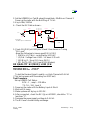
NO CHARGER
TEST CONDICTION: RADIO SUPPLY FROM
EXT B+ AND IN TEST-MODE
CHECK 2.75V
THERMISTOR
ON PIN12 OF
J400?
NO
CHECK FOR Q604
DAMAGE
YES
CHECK 8V ON
PIN4 OF Q601?
NO
YES
CHECK 0V ON
PIN17 OF
U900?
ENTER
500255# AND
CHECK FOR 0V
ON PIN 4 OF
Q601?
YES
REPLACE
U900
NO
NO
NO
TRY TO REFLEX
RADIO VIA MASTER
CARD AND AFTER
REPLACE U703 BIC.
YES CHECK FOR 8V
ON PIN5.6.7.8.
OF Q601 IF IS
NOT CORRECT
REPLACE Q601.
YES
CHECK 2.75V
ON PIN17 OF
U900?
REPLACE
U900
P20
NO OR LOW RING TONE
START
IS THE SIGNAL
CORRECT AT
PIN 4 OF
U803?
NO
RT 1
YES
RT 3
YES
IS THE SIGNAL
CORRECT AT
PIN 4 OF U900
NO
RT 2
RT1: CHECK IF U801 IS POSITIONED CORRECTLY OR BAD SOLDER, IF ANY
MENTIONED PROBLEM ARE PRESENT REPLACE U801
RT2: CHECK IF U802 AND U803 ARE POSITIONED CORRECTLY OR BAD SOLDER
ALSO CHECK C825,C817 AND R803. IF ANY MENTIONED PROBLEM ARE
PRESENT REPLACE U803
RT3: CHECK IF U900 IS POSITIONED CORRECTLY OR BAD SOLDER AT PIN
4.5.6.7, CHECK ALSO PIN CONNECTOR 5.7 OF J2. IF ANY MENTIONED
PROBLEM ARE PRESENT REPLACE U900.
NO OR LOW AUDIO VOLUME
START
IS SIGNAL
CORRECT AT
PIN 4 OF
U803?
NO
AV1
YES
YES
AV3
IS SIGNAL
CORRECT AT
PIN 21 OF
U900?
NO
AV2
P1
AV1: CHECK IF U801 AND U803 ARE POSITIONED CORRECTLY OR BAD SOLDER IF
ANY MENTIONED PROBLEM ARE PRESENT REPLACE U803.
AV2: CHECK IFU802 AND U803 ARE POSITIONED CORRECTLY OR BAD SOLDER, ALSO
CHECK C825 AND R810. IF ANY MENTIONED PROBLEM ARE PRESENT REPLACE U803.
AV3: CHECK IF U900 IS POSITIONED CORRECTLY OR BAD SOLDER AT PIN 19.20.21,
PIN CONNECTOR 22.20 OF J2 AND R802,R810,C804 AND C825. IF ANY MENTIONED
PROBLEM ARE PRESENT REPLACE U900.
NO OR LOW AUDIO MICROPHONE
START
IS AUDIO
CORRECT ON
PIN 10 OF
U900?
NO
MIC 01
YES
IS AUDIO
CORRECTON
PIN 17
OFU803?
NO
MIC02
YES
MIC 04
YES
IS AUDIO
DIGITAL
CORRECT ON
PIN 84 OF
U801?
NO
MIC 03
MIC 01: CHECK J802, C810, C813, C808, R806, R805 FOR BAD
SOLDER.
MIC02: CHECK VOLTAGE ON PIN 17/18/19/20 OF U803, IS ABOUT 2.4V, IF IS
NOT CORRECT REPLACE C832 AND C848; IF IS CORRECT CHECK U900 AND
AFTER REPLACE IT.
MIC 03: CHECK IF U803 AND R838, R842, R841 ARE POSITIONED CORRECTLY OR
BAD SOLDER AFTER REPLACE U803.
MIC 04: CHECK IF U801 AND R845 ARE POSITIONED CORRECTLY OR BAD SOLDER
AFTER REPLACE U801.
1
DOES R275
CORRECT AT
PIN 28 OF
U900?
NO
PROCEED
TO NPU6
ON PAGE 6
YES
DOES R475
CORRECT AT
PIN 41 OF
U900?
NO
PROCEED
TO NPU7
ON PAGE 6
YES
IS 13MHz
PRESENT AT
PIN 37 OF
U703?
NO
PROCEED
TO NPU8
ON PAGE 6
YES
IS 13MHz
PRESENT AT
PIN 51 OF
U701?
NO
PROCEED
TO NPU9
ON PAGE 7
YES
DOES THE
RESET LINE
GO HIGH ON
PIN 30 OF
U900?
NO
PROCEED
TO NPU10
ON PAGE 7
YES
REMOVE SHORT ON
WATCHDOG PULL UP PADS
DOES THE
WATCHDOG
LINE GO HIGH
ON PIN 31 OF
U900?
YES
2
NO
PROCEED
TO NPU11
ON PAGE 7
2
TIE THE WATCHDOG HIGH BY
SHORTING TOGETHER THE
WATCHDOG PULL UP PADS.
YES
NO
IS THE
NOCE
PRESENT ON
PIN 26 OF
U702?
PROCEED
TO NPU12
ON PAGE 7
YES
IS THE CE
NO ON
PRESENT
PIN 39 AND 40
OF U704?
NO
PROCEED
TO NPU13
ON PAGE 7
YES
IS THE CE
NO ON
PRESENT
PIN 27 OF
U705?
YES
TRY TO RESOLDER FLASH-PROM
U702 AND AFTER REPLACE IT.
NO
PROCEED
TO NPU14
ON PAGE 7
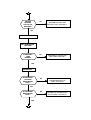
START
IS B+ PRESENT
AT PIN 48 OF
U900?
NO
PROCEED
TO NPU1
ON PAGE 6
YES
TIE THE WATCHDOG HIGH BY
SHORTING TOGETHER THE
WATCHDOG PULL UP PADS.
YES
DOES 3.25V
VSWITCH
CORRECTAT
PIN 25 OF
U900?
NO
PROCEED
TO NPU2
ON PAGE 6
YES
DOES LX
300KHz
PRESENT AT
PIN 37 OF
U900?
NO
PROCEED
TO NPU3
ON PAGE 6
YES
DOES L275
CORRECT AT
PIN 22 OF
U900?
NO
PROCEED
TO NPU5
ON PAGE 6
YES
DOES L500
CORRECT AT
PIN 3 OF
U900?
NO
PROCEED
TO NPU4
ON PAGE 6
1
P3
POWERS OFF WHEN TWISTED
CHECK Y201, CR201, U201, U702, U704 FOR POSITIONED CORRECTLY OR BAD SOLDER
WILL NOT POWERS DOWN
CHECK IF THERE ISN’T ANY SHORT ON WATCHDOG PULL UP PADS. CHECK ALSO
CONNECTION FROM PIN 25 OF J2 TO R990 OR BAD SOLDER ON U900. IF ANY
MENTIONED PROBLEM ARE PRESENT REPLACE U900.
FREQUENCY ERROR OUT OF SPEC.
CHECK Y201 AND CR 201 FOR PHISICALLY DAMAGE OR BAD SOLDER.
PHASE ERROR OUT OF SPEC.
START
ARE TXI & TXQ
CORRECT AT
PIN 61.63 OF
U201?
YES
CHECK FOR RIGTH
FREQUENCY 216MHz
ON C228 AND 108MHz
AT PIN 4 OF U201. TRY
TO REPHASE AND
AFTER REPLACE U201.
NO
CHECK U501 FOR
PHISICALLY DAMAGE
OR BAD SOLDER,
AFTER REPLACE IT.
IS B+
PRESENT AT
PIN 1 OF
Q999?
NO
RETURN PCB TO
HI-TECH.
YES
CHECK POLARITY
OF C907 AND
CR998. AFTER
REPLACE CR 998.
NPU3: CHECK CR910 C916 FOR POLARITY AFTER REPLACE
T900.
NPU4: CHECK POLARITY OF C901 AND AFTER REPLACE
U900.
NPU6: CHECK C908 FOR SHORT CIRCUIT AND AFTER REPLACE
U900.
NPU7: CHECK POLARITY OF C906 AND AFTER REPLACE U900.
NPU8:
IS 13 MHz CKIN
PRESENT ON
PIN 17 OF U703?
YES
CHECK R714,
C701 AND AFTER
REPLACE U703.
NO
CHECK
VOLTAGE ON
Q203 AND
Q202, IS
2.75V?
YES
CHECK CR201,
Y201 AND U201
NO
CHECK C212, C214
AND AFTER REPLACE
Q202/Q203.
P6
NPU9: CHECK TRACK FROM R714 TO PIN 51 OF U701.
NPU10: CHECK SOLDER ON U900, TRY TO RESOLDER U702
OR CONNECT RADIO TO THE EMMIBOX FOR UPGRADE.
NPU11: CHECK WATCHDOG LINE FROM PIN 31 OF U900 TO R741/PIN 56 OF U703, AND
FROM PIN 31 OF U900 TO PIN 60 OF U701. IF ANY MENTIONED PROBLEM ARE PRESENT
REPLACE U900.
NPU12: U701 BEING SENT CE TO U704. CONTROL CE LINE FROM PIN 100 OF U701 TO PIN 26
OF U702, IF IS CORRECT REPLACE U702.
NPU13: U701 BEING SENT CE FROM PIN 102 TO PIN 40 OF U704. IF IS CORRECT REPLACE
U704.
NPU14: U701 BEING SENT CE FROM PIN 114 TO PIN 27 OF U705 TRY
TO CONNECT RADIO TO THE EMMIBOX FOR UPGRADE THE RADIO.
WILL NOT INITIATE A CALL
IMPULSIVE
11062# 1200#
310#
CONTINUOS
11062# 1215# 40#
START
IS 902.4MHz TX
SIGNAL
CORRECT AT
TX1 PIN 8 OF
U400?
YES
TX REPAIR 1
NO
IS 902.4MHz TX
SIGNAL
CORRECT AT
TX2 ON L302?
YES
TX REPAIR 2
NO
IS 902.4MHz TX
SIGNAL
CORRECT AT TX
3 BASE OF
Q302?
YES
TX REPAIR 3
NO
IS 902.4MHz TX
SIGNAL
CORRECT AT
TX4 ON BASE
OF Q381
YES
TX REPAIR 4
NO
1
P9
WILL NOT INITIATE A CALL
1
IS 902.4MHz TX
SIGNAL
CORRECT AT
TX5 ON BASE
OF Q300?
YES
TX REPAIR 5
NO
IS108MHz IF
SIGNAL
CORRECT AT
TX 6 ON PIN 4
OF U300?
YES
TX REPAIR 6
NO
TX REPAIR 7
TX1: CHECKC442, L433 AND AFTER REPLACE
U400
TX2: CHECK C439, L302.303.304, C328 AND C329 FOR PHISICALLY DAMAGE OR BAD SOLDER.
TX3: CHECK IF B+ IS PRESENT ON COLLECTOR OF Q302 AND PIN 2.3 OF Q301. IF B+ IS
CORRECT TRACE THE TX SIGNAL TROUGH THE PATH FROM Q302 TO Q301 TO DECIPHER
WICH IS THE FAILURE COMPONENT.
TX4: TAKES DC VOLTAGE MEASUREMENT AS
FOLLOWING:
B+ C
E 0.3V
Q 381
B 0.5V
IF THE COLLECTOR IS NOT SUPPLIED BY B+ CHANGE L380. IF B+ IS CORRECT REPLACE
Q381.
P10
WILL NOT INITIATE A CALL
1.2V B
Q 300
C 2.7V
0.6V E
IF THE COLLECTOR IS NOT SUPLLIED BY 2.7V CHECK C 301.302.325. IF 2.7V ON
COLLECTOR IS OK CHECK C 304.314.381 R352 AND AFTER REPLACE Q300.
TX6:
PIN7
DM_CS
PIN6
GND
PIN5
GND
6
5
7
PIN4 IF PIN3
108MHz GND
4
PIN2
R275
PIN1 TX
VCO
796.4MHz
3
2
1
12
13
14
U 300 TIC
8
PIN8 CP
OUT
2.1V
9
10
11
PIN9
R475
PIN10
R475
PIN11 PIN12 PIN13 PIN14 RX
GND R275 GND
VCO
902.4MHz
CHECK PRESENCE OF SIGAL FOLLOWING THE SCHEMATIC AS ABOVE TO DECIPHER
WICH IS THE FAULTY LINE. IF EVERITHINGS ARE CORRECT REPLACE U300.
TX7:
IS 216MHz
PRESENT ON
C228?
NO
YES
REPLACE
Q203
NO
IS RX 2.75V
PRESENT AT
PIN 3 OF
U201?
IS R475
PRESENT AT
PIN 44 OF
U201?
NO
CHECK
U900 PIN
41.
YES
CHECK FOR BAD SOLDER
U201 AND AFTER REPLACE
IT.
YES
CHECK FOR BAD SOLDER CR203,
L203.AFTER REPLACE REPLACE U201
P11
NO SERVICE AT -102dBm
SET THE COMMUNICATIONANALYZER TO INJECT VIA ANTENNA PLUG -30dBm AT 947.4MHz,
PUT THE RADIO IN TEST MODE AND LOAD SYNTHETIZER WITH 33062# COMMAND.
START
IS RX1
947.4MHz RX
SIGNAL
CORRECT ON
PIN 5 OF U400?
NO
RX REPAIR 1
YES
IS RX2
947.4MHz RX
SIGNAL
CORRECT ON
C407?
NO
RX REPAIR 2
YES
IS RX3
947.4MHz RX
SIGNAL
CORRECT ON
C408?
NO
RX REPAIR 3
YES
IS RX4
947.4MHz RX
SIGNAL
CORRECT ON
C409?
NO
RX REPAIR 4
YES
IS RX4 794.4
MHz VCO
SIGNAL
CORRECT ON
C409?
NO
VCO REPAIR
YES
1
P12
NO SERVICE AT -102dBm
1
IS RX5 153MHz
CORRECT ON
R426?
NO
RX REPAIR 5
YES
IS RX6 153MHz
CORRECT ON
C421?
NO
RX REPAIR 6
YES
IS RX7 153MHz
CORRECT ON
PIN 31 OF
U201?
NO
RX REPAIR 7
YES
ARE RXI AND
RXQ CORRECT
AT PIN 14 AND
15 OF U501?
NO
RX REPAIR 8
YES
ARE THE SPI
ACTIVITY
PRESENT AT
PIN 4, 6 AND 8
OF U501?
NO
RX REPAIR 9
YES
TRY TO REPHASE VIA GATE 22, IF STILL NO
FUNCTION CHANGE U501. IF ANY
MENTIONED ACTION RESOLVE THE
PROBLEM RETURN PCB TO HI-TECH
CENTRE.
P13
NO SERVICE AT -102dBm
RX1: FROM ANTENNA PORT CHECK L439, C440 FOR BAD SOLDER AND AFTER REPLACE
U400. FROM SWITCH RF CHECK L443, C442 FOR BAD SOLDER AND AFTER REPLACE
U400.
RX2:CHECK IF FL451 IS POSITIONED CORRECTLY OR BAD SOLDER. IF ANY
MENTIONED PROBLEM ARE PRESENT REPLACE FL451.
RX3:TAKES ON Q418 DC MEASUREMENT LIKE AS FOLLOWING:
1.3V B
Q 418 C 2.7V
0.5V E
# IF THE COLLECTOR IS NOT SUPLLY BY RX275, CHECK Q203 AND ASSOCIATE
CIRCUITRY.AFTER REPLACE Q203.
# IF THE COLLECTOR IS SUPLLY BY RX275 FROM Q203 CHECK L412, R432
AND AFTER REPLACE Q418.
RX4:CHECK FL452 FOR PHICALLY DAMAGE OR BAD SOLDER. IF ANY
MENTIONED PROBLEM ARE PRESENT REPLACE FL452.
RX5: TAKES ON Q420 DC MEASUREMENT VOLTAGE LIKE AS
FOLLOWING:
1V B
Q 420 C 2.7V
0.37 E
# IF THE COLLECTOR IS NOT SUPPLY BY RX275, CHECK L414 AND AFTER REPLACE
Q203.
# IF THE COLLECTOR SUPLLY IS CORRECT REPLACE
Q420.
RX6:CHECK FL420 IF IS NOT PHISICALLY DAMAGE OR BAD SOLDER. IF ANY
MENTIONED PROBLEM ARE PRESENT REPLACE FL420.
RX7:TAKES ON Q421 DC MEASUREMENT VOLTAGE LIKE AS FOLLOWING:
0V B
Q 421 C 1.9V
0.6V E
# IF THE COLLECTOR SUPPLY IS CORRECT REPLACE
Q421.
# IF THE COLLECTOR IS NOT SUPPLY BY PIN 33 OF U201, CHECK R423 AND
AFTER REPLACE U201.
P14
RX:8
START
IS RX LOCAL
OSC. 306MHz
PRESENT ON
PIN 39 OF
U201?
NO
RX LOCAL OSC.1
YES
RX LOCAL OSC.2
RX9:IF THERE IS NOT ACTIVITY ON SPI BUS TRY TO REPHASE AND AFTER REPLACE
U501.
RX LOCAL OSC.1:CHECK FOR CR431, L433 AND U201 PHISICALLY DAMAGE OR BAD
SOLDER. IF ANY MENTIONED PROBLEM ARE PRESENT REPLACE U201.
RX LOCAL OSC.2:CHECK IQ_ REF FROM PIN 16 OF U501 TO PIN47 OF U201, 1.38V IS
CORRECT CONTROL FROM MODEM.
# IF THE CONTROL IS CORRECT CHANGE U201.
# IF THE CONTROL IS NOT CORRECT, TRY TO REPHASE AND AFTER REPLACE
U501.
P15
VCO REPAIR:
START
IS VCO
794.4MHz
CORRECT AT
PIN 4 OF
FL453?
YES
VCO REPAIR 1
NO
IS 2.5V VCO
SUPPLY
CORRECT
FROM PIN 21
OF U201?
NO
VCO REPAIR 2.
YES
RETUR PCB TO
HI-TECH.
VCO REPAIR 1:CHECK IF FL453 IS NOT PHISICALLY DAMAGE OR BAD SOLDER. IF ANY
MENTIONED PROBLEM ARE PRESENT REPLACE FL453.
VCO REPAIR 2:CHECK SUPPLIES FROM Q203 AND Q202. IF THEY ARE INCORRECT TAKES
REFERENCE FROM A FULLY FUNCTIONALLY PCB TO DECIPHER WHICH COMPONENTS
CAUSES NO OR POOR SUPER FILTER SUPPLY FOR VCO.POSSIBLE DEFECTIVE
COMPONENTS ARE Q202, Q203,C212,C214 AND U201.
P16
POWER BURST OUT OF SPEC.
FOLLOWING THE SCHEMATIC OF PAC_IC U310 CHECK THE PIN 7 (PA
CONTROL) IF IS CORRECT REPLACE Q301, Q302. IF IS NOT CORRECT CHECK
THE OTHER PIN TO TRACE THE FAULTY LINE.
PIN7
EXC.
PIN4
PAC_ENI
7
4
PIN2 RF
SAT_DET
2
PIN1
GND
1
U 310 PAC IC
8.9
10
11
PIN9
AOC
PIN10
TX_KEY
PIN11
DET__SW
12
PIN12
SAT_DET
14
PIN14
PAC_ENI
IF ANY MENTIONED PROBLEMS ARE PRESENT RETURN PCB TO HI-TECH.
P17
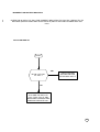
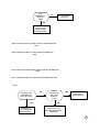
INCORRECT LOW BATTERY INDICATION
NO OR LOW DISPLAY
START
YES
IS PIN 4 OF U101
AT -9.6V ?
CHECK FOR BAD
SOLDER ON Q102
AFTER REPLACE IT.
NO
CHECK L500 ON PIN 6 OF
U101 AND POLARITY OF
C101, C102, C103. IF ANY
MENTIONED PROBLEM ARE
PRESENT REPLACE U101.
P18
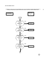
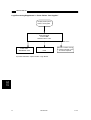
8700 PROCEDURE LVL3
START
DOES PCB
POWER UP
CORRECTLY.?
NO
ed. 1.1
PROCEED TO "WILL NOT POWERS
& STAY ON" ON PAGE 3
YES
YES
DOES PCB
DRAWS
CURRENT
WHEN IS OFF?
PROCEED TO "DRAWS CURRENT
WHEN IS OFF" ON PAGE 19
NO
DOES PCB
POWER DOWN
WHEN
TWISTED?
YES
PROCEED TO "POWER OFF
WHEN TWISTED" ON PAGE 8
NO
DOES WAKE
UP DISPLAY
CORRECT.?
NO
PROCEED TO "NO OR
LOW DISPLAY" ON PAGE
18
YES
PROCEED TO "PHONE
FAILURE SEE SUPPLIER" ON
PAGE 19
NO
PROCEED TO "NO
SERVICE AT -102dBm" ON
PAGE 12
YES
DOES DISPLAY
SHOW "PHONE
FAILURE SEE
SUPPLIER"?
NO
DOES PCB GO
INTO SERVICE
AT -102dBm?
YES
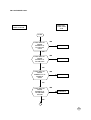
1
1
CAN PCB
INITIATE A
CALL TO THE
ANALYZER?
NO
PROCEED TO "WILL NOT
INITIATE A CALL" ON PAGE 9
YES
TERMINATE THE CALL
CALL MOBILE FROM
ANALYZER
IS RING AUDIO
TONE
AUDIBILE?
NO
PROCEED TO "NO OR LOW
RING TONE" ON PAGE 1
YES
ANSWER CALL.
IS THE TX FREQ
OR PHASE
ERROR WITHIN
SPEC.?
NO
PROCEED TO "FREQ ERR." OR
"PHASE ERROR OUT OF
SPEC." ON PAGE 8
YES
IS THE POWER
BURST WITHIN
SPEC.?
YES
2
NO
PROCEED TO "POWER BURST
OUT OF SPEC." ON PAGE 17
2
IS THE TX
AUDIO PATH
OK.?
NO
PROCEED TO "NO OR LOW
AUDIO VOLUME" ON PAGE 1
YES
IS AUDIO
LOOP-BACK
CORRECT.?
NO
PROCEED TO "NO OR LOW AUDIO
MICROPHONE" ON PAGE 2
YES
TERMINATE THE CALL
IS THE LOW
BATTERY
INDICATION
CORRECT.?
NO
PROCEED TO "INCORRECT LOW
BATTERY INDICATION"ON PAGE 18
YES
NO
DOES THE
CHARGER
FUNCTION
CORRECTLY?
YES
NO FAULT FOUND
PROCEED TO "NO
CHARGER" ON PAGE 20
PCB DRAWS CURRENT WHEN IS OFF
CHECK TRANSISTOR REGULATOR: Q202, Q203 AND U201 ARE NOT PHISCALLY
DAMAGE; CHECK ALSO U900 TO MONITORING WHICH COMPONENT BECOMING
WARMER AFTER REPLACE IT.
B+
P.A. MOD.
Q301.302
VREF. FROM
U900
U201
B+
Q202
U900
2.75V
Q203
2.75V
PHONE FAILED SEE SUPPLIER
ENTER 7100# , 7101# AND
REPORT THE CODES
04/XX
CHECK Q203 FOR RX
275: IF IS NOT
CORRECT REPLACE
Q203; IF IS CORRECT
REPLACE U501.
07/XX
TRY TO REFLEX U702
VIA EMMIBOX OR
MASTER CARD IF
STILL NOT CORRECT
SEND TO HI-TECH.
05/XX
ENTER 171# AND 57#
AND POWER UP THE
RADIO AGAIN. IF STILL
NOT CORRECT
CHECK FOR 26 MHz
FROM PIN 6 OF U805:
IF IS OK REPLACE
U801, IF IS NOT OK
REPLACE U805.
P19
NO CHARGER
TEST CONDICTION: RADIO SUPPLY FROM
EXT B+ AND IN TEST-MODE
CHECK 2.75V
THERMISTOR
ON PIN12 OF
J400?
NO
CHECK FOR Q604
DAMAGE
YES
CHECK 8V ON
PIN4 OF Q601?
NO
YES
YES
REPLACE
U900
ENTER
500255# AND
CHECK FOR
0V ON PIN 4
OF Q601?
CHECK 0V ON
PIN17 OF
U900?
NO
CHECK FOR 8V
ON PIN5.6.7.8.
OF Q601 IF IS
NOT CORRECT
REPLACE Q601.
NO
NO
TRY TO REFLEX
RADIO VIA MASTER
CARD AND AFTER
REPLACE U703 BIC.
YES
YES
CHECK 2.75V
ON PIN17 OF
U900?
REPLACE
U900
P20
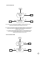
NO OR LOW RING TONE
START
IS THE SIGNAL
CORRECT AT
PIN 4 OF
U803?
NO
RT 1
YES
RT 3
YES
IS THE SIGNAL
CORRECT AT
PIN 4 OF U900
NO
RT 2
RT1: CHECK IF U801 IS POSITIONED CORRECTLY OR BAD SOLDER, IF ANY
MENTIONED PROBLEM ARE PRESENT REPLACE U801
RT2: CHECK IF U802 AND U803 ARE POSITIONED CORRECTLY OR BAD SOLDER
ALSO CHECK C825,C817 AND R803. IF ANY MENTIONED PROBLEM ARE
PRESENT REPLACE U803
RT3: CHECK IF U900 IS POSITIONED CORRECTLY OR BAD SOLDER AT PIN
4.5.6.7, CHECK ALSO PIN CONNECTOR 5.7 OF J2. IF ANY MENTIONED
PROBLEM ARE PRESENT REPLACE U900.
NO OR LOW AUDIO VOLUME
START
IS SIGNAL
CORRECT AT
PIN 4 OF
U803?
NO
AV1
YES
YES
AV3
IS SIGNAL
CORRECT AT
PIN 21 OF
U900?
NO
AV2
P1
AV1: CHECK IF U801 AND U803 ARE POSITIONED CORRECTLY OR BAD SOLDER IF
ANY MENTIONED PROBLEM ARE PRESENT REPLACE U803.
AV2: CHECK IFU802 AND U803 ARE POSITIONED CORRECTLY OR BAD SOLDER, ALSO
CHECK C825 AND R810. IF ANY MENTIONED PROBLEM ARE PRESENT REPLACE U803.
AV3: CHECK IF U900 IS POSITIONED CORRECTLY OR BAD SOLDER AT PIN 19.20.21,
PIN CONNECTOR 22.20 OF J2 AND R802,R810,C804 AND C825. IF ANY MENTIONED
PROBLEM ARE PRESENT REPLACE U900.
NO OR LOW AUDIO MICROPHONE
START
IS AUDIO
CORRECT ON
PIN 10 OF
U900?
NO
MIC 01
YES
IS AUDIO
CORRECTON
PIN 17
OFU803?
NO
MIC02
YES
MIC 04
YES
IS AUDIO
DIGITAL
CORRECT ON
PIN 84 OF
U801?
NO
MIC 03
MIC 01: CHECK J802, C810, C813, C808, R806, R805 FOR BAD
SOLDER.
MIC02: CHECK VOLTAGE ON PIN 17/18/19/20 OF U803, IS ABOUT 2.4V, IF IS
NOT CORRECT REPLACE C832 AND C848; IF IS CORRECT CHECK U900 AND
AFTER REPLACE IT.
MIC 03: CHECK IF U803 AND R838, R842, R841 ARE POSITIONED CORRECTLY OR
BAD SOLDER AFTER REPLACE U803.
MIC 04: CHECK IF U801 AND R845 ARE POSITIONED CORRECTLY OR BAD SOLDER
AFTER REPLACE U801.
1
DOES R275
CORRECT AT
PIN 28 OF
U900?
NO
PROCEED
TO NPU6
ON PAGE 6
YES
DOES R475
CORRECT AT
PIN 41 OF
U900?
NO
PROCEED
TO NPU7
ON PAGE 6
YES
IS 13MHz
PRESENT AT
PIN 37 OF
U703?
NO
PROCEED
TO NPU8
ON PAGE 6
YES
IS 13MHz
PRESENT AT
PIN 51 OF
U701?
NO
PROCEED
TO NPU9
ON PAGE 7
YES
DOES THE
RESET LINE
GO HIGH ON
PIN 30 OF
U900?
NO
PROCEED
TO NPU10
ON PAGE 7
YES
REMOVE SHORT ON
WATCHDOG PULL UP PADS
DOES THE
WATCHDOG
LINE GO HIGH
ON PIN 31 OF
U900?
YES
2
NO
PROCEED
TO NPU11
ON PAGE 7
2
TIE THE WATCHDOG HIGH BY
SHORTING TOGETHER THE
WATCHDOG PULL UP PADS.
YES
NO
IS THE
NOCE
PRESENT ON
PIN 26 OF
U702?
PROCEED
TO NPU12
ON PAGE 7
YES
IS THE CE
NO ON
PRESENT
PIN 39 AND 40
OF U704?
NO
PROCEED
TO NPU13
ON PAGE 7
YES
IS THE CE
NO ON
PRESENT
PIN 27 OF
U705?
YES
TRY TO RESOLDER FLASH-PROM
U702 AND AFTER REPLACE IT.
NO
PROCEED
TO NPU14
ON PAGE 7
START
IS B+ PRESENT
AT PIN 48 OF
U900?
NO
PROCEED
TO NPU1
ON PAGE 6
YES
TIE THE WATCHDOG HIGH BY
SHORTING TOGETHER THE
WATCHDOG PULL UP PADS.
YES
DOES 3.25V
VSWITCH
CORRECTAT
PIN 25 OF
U900?
NO
PROCEED
TO NPU2
ON PAGE 6
YES
DOES LX
300KHz
PRESENT AT
PIN 37 OF
U900?
NO
PROCEED
TO NPU3
ON PAGE 6
YES
DOES L275
CORRECT AT
PIN 22 OF
U900?
NO
PROCEED
TO NPU5
ON PAGE 6
YES
DOES L500
CORRECT AT
PIN 3 OF
U900?
NO
PROCEED
TO NPU4
ON PAGE 6
1
P3
POWERS OFF WHEN TWISTED
CHECK Y201, CR201, U201, U702, U704 FOR POSITIONED CORRECTLY OR BAD SOLDER
WILL NOT POWERS DOWN
CHECK IF THERE ISN’T ANY SHORT ON WATCHDOG PULL UP PADS. CHECK ALSO
CONNECTION FROM PIN 25 OF J2 TO R990 OR BAD SOLDER ON U900. IF ANY
MENTIONED PROBLEM ARE PRESENT REPLACE U900.
FREQUENCY ERROR OUT OF SPEC.
CHECK Y201 AND CR 201 FOR PHISICALLY DAMAGE OR BAD SOLDER.
PHASE ERROR OUT OF SPEC.
START
ARE TXI & TXQ
CORRECT AT
PIN 61.63 OF
U201?
YES
CHECK FOR RIGTH
FREQUENCY 216MHz
ON C228 AND 108MHz
AT PIN 4 OF U201. TRY
TO REPHASE AND
AFTER REPLACE U201.
NO
CHECK U501 FOR
PHISICALLY DAMAGE
OR BAD SOLDER,
AFTER REPLACE IT.
IS B+
PRESENT AT
PIN 1 OF
Q999?
NO
RETURN PCB TO
HI-TECH.
YES
CHECK POLARITY
OF C907 AND
CR998. AFTER
REPLACE CR 998.
NPU3: CHECK CR910 C916 FOR POLARITY AFTER REPLACE
T900.
NPU4: CHECK POLARITY OF C901 AND AFTER REPLACE
U900.
NPU6: CHECK C908 FOR SHORT CIRCUIT AND AFTER REPLACE
U900.
NPU7: CHECK POLARITY OF C906 AND AFTER REPLACE U900.
NPU8:
IS 13 MHz CKIN
PRESENT ON
PIN 17 OF U703?
YES
CHECK R714,
C701 AND AFTER
REPLACE U703.
NO
CHECK
VOLTAGE ON
Q203 AND
Q202, IS
2.75V?
YES
CHECK CR201,
Y201 AND U201
NO
CHECK C212, C214
AND AFTER REPLACE
Q202/Q203.
P6
NPU9: CHECK TRACK FROM R714 TO PIN 51 OF U701.
NPU10: CHECK SOLDER ON U900, TRY TO RESOLDER U702
OR CONNECT RADIO TO THE EMMIBOX FOR UPGRADE.
NPU11: CHECK WATCHDOG LINE FROM PIN 31 OF U900 TO R741/PIN 56 OF U703, AND
FROM PIN 31 OF U900 TO PIN 60 OF U701. IF ANY MENTIONED PROBLEM ARE PRESENT
REPLACE U900.
NPU12: U701 BEING SENT CE TO U704. CONTROL CE LINE FROM PIN 100 OF U701 TO PIN 26
OF U702, IF IS CORRECT REPLACE U702.
NPU13: U701 BEING SENT CE FROM PIN 102 TO PIN 40 OF U704. IF IS CORRECT REPLACE
U704.
NPU14: U701 BEING SENT CE FROM PIN 114 TO PIN 27 OF U705 TRY
TO CONNECT RADIO TO THE EMMIBOX FOR UPGRADE THE RADIO.
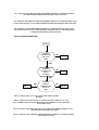
WILL NOT INITIATE A CALL
IMPULSIVE
11062# 1200#
310#
CONTINUOS
11062# 1215# 40#
START
IS 902.4MHz TX
SIGNAL
CORRECT AT
TX1 PIN 8 OF
U400?
YES
TX REPAIR 1
NO
IS 902.4MHz TX
SIGNAL
CORRECT AT
TX2 ON L302?
YES
TX REPAIR 2
NO
IS 902.4MHz TX
SIGNAL
CORRECT AT TX
3 BASE OF
Q302?
YES
TX REPAIR 3
NO
IS 902.4MHz TX
SIGNAL
CORRECT AT
TX4 ON BASE
OF Q381
YES
TX REPAIR 4
NO
1
P9
WILL NOT INITIATE A CALL
1
IS 902.4MHz TX
SIGNAL
CORRECT AT
TX5 ON BASE
OF Q300?
YES
TX REPAIR 5
NO
IS108MHz IF
SIGNAL
CORRECT AT
TX 6 ON PIN 4
OF U300?
YES
TX REPAIR 6
NO
TX REPAIR 7
TX1: CHECKC442, L433 AND AFTER REPLACE
U400
TX2: CHECK C439, L302.303.304, C328 AND C329 FOR PHISICALLY DAMAGE OR BAD SOLDER.
TX3: CHECK IF B+ IS PRESENT ON COLLECTOR OF Q302 AND PIN 2.3 OF Q301. IF B+ IS
CORRECT TRACE THE TX SIGNAL TROUGH THE PATH FROM Q302 TO Q301 TO DECIPHER
WICH IS THE FAILURE COMPONENT.
TX4: TAKES DC VOLTAGE MEASUREMENT AS
FOLLOWING:
B+ C
E 0.3V
Q 381
B 0.5V
IF THE COLLECTOR IS NOT SUPPLIED BY B+ CHANGE L380. IF B+ IS CORRECT REPLACE
Q381.
P10
WILL NOT INITIATE A CALL
1.2V B
Q 300
C 2.7V
0.6V E
IF THE COLLECTOR IS NOT SUPLLIED BY 2.7V CHECK C 301.302.325. IF 2.7V ON
COLLECTOR IS OK CHECK C 304.314.381 R352 AND AFTER REPLACE Q300.
TX6:
PIN7
DM_CS
PIN6
GND
PIN5
GND
6
5
7
PIN4 IF PIN3
108MHz GND
4
PIN2
R275
PIN1 TX
VCO
796.4MHz
3
2
1
12
13
14
U 300 TIC
8
PIN8 CP
OUT
2.1V
9
10
11
PIN9
R475
PIN10
R475
PIN11 PIN12 PIN13 PIN14 RX
GND R275 GND
VCO
902.4MHz
CHECK PRESENCE OF SIGAL FOLLOWING THE SCHEMATIC AS ABOVE TO DECIPHER
WICH IS THE FAULTY LINE. IF EVERITHINGS ARE CORRECT REPLACE U300.
TX7:
IS 216MHz
PRESENT ON
C228?
NO
YES
REPLACE
Q203
NO
IS RX 2.75V
PRESENT AT
PIN 3 OF
U201?
IS R475
PRESENT AT
PIN 44 OF
U201?
NO
CHECK
U900 PIN
41.
YES
CHECK FOR BAD SOLDER
U201 AND AFTER REPLACE
IT.
YES
CHECK FOR BAD SOLDER CR203,
L203.AFTER REPLACE REPLACE U201
P11
NO SERVICE AT -102dBm
SET THE COMMUNICATIONANALYZER TO INJECT VIA ANTENNA PLUG -30dBm AT 947.4MHz,
PUT THE RADIO IN TEST MODE AND LOAD SYNTHETIZER WITH 33062# COMMAND.
START
IS RX1
947.4MHz RX
SIGNAL
CORRECT ON
PIN 5 OF U400?
NO
RX REPAIR 1
YES
IS RX2
947.4MHz RX
SIGNAL
CORRECT ON
C407?
NO
RX REPAIR 2
YES
IS RX3
947.4MHz RX
SIGNAL
CORRECT ON
C408?
NO
RX REPAIR 3
YES
IS RX4
947.4MHz RX
SIGNAL
CORRECT ON
C409?
NO
RX REPAIR 4
YES
IS RX4 794.4
MHz VCO
SIGNAL
CORRECT ON
C409?
NO
VCO REPAIR
YES
1
P12
NO SERVICE AT -102dBm
1
IS RX5 153MHz
CORRECT ON
R426?
NO
RX REPAIR 5
YES
IS RX6 153MHz
CORRECT ON
C421?
NO
RX REPAIR 6
YES
IS RX7 153MHz
CORRECT ON
PIN 31 OF
U201?
NO
RX REPAIR 7
YES
ARE RXI AND
RXQ CORRECT
AT PIN 14 AND
15 OF U501?
NO
RX REPAIR 8
YES
ARE THE SPI
ACTIVITY
PRESENT AT
PIN 4, 6 AND 8
OF U501?
NO
RX REPAIR 9
YES
TRY TO REPHASE VIA GATE 22, IF STILL NO
FUNCTION CHANGE U501. IF ANY
MENTIONED ACTION RESOLVE THE
PROBLEM RETURN PCB TO HI-TECH
CENTRE.
P13
NO SERVICE AT -102dBm
RX1: FROM ANTENNA PORT CHECK L439, C440 FOR BAD SOLDER AND AFTER REPLACE
U400. FROM SWITCH RF CHECK L443, C442 FOR BAD SOLDER AND AFTER REPLACE
U400.
RX2:CHECK IF FL451 IS POSITIONED CORRECTLY OR BAD SOLDER. IF ANY
MENTIONED PROBLEM ARE PRESENT REPLACE FL451.
RX3:TAKES ON Q418 DC MEASUREMENT LIKE AS FOLLOWING:
1.3V B
Q 418 C 2.7V
0.5V E
# IF THE COLLECTOR IS NOT SUPLLY BY RX275, CHECK Q203 AND ASSOCIATE
CIRCUITRY.AFTER REPLACE Q203.
# IF THE COLLECTOR IS SUPLLY BY RX275 FROM Q203 CHECK L412, R432
AND AFTER REPLACE Q418.
RX4:CHECK FL452 FOR PHICALLY DAMAGE OR BAD SOLDER. IF ANY
MENTIONED PROBLEM ARE PRESENT REPLACE FL452.
RX5: TAKES ON Q420 DC MEASUREMENT VOLTAGE LIKE AS
FOLLOWING:
1V B
Q 420 C 2.7V
0.37 E
# IF THE COLLECTOR IS NOT SUPPLY BY RX275, CHECK L414 AND AFTER REPLACE
Q203.
# IF THE COLLECTOR SUPLLY IS CORRECT REPLACE
Q420.
RX6:CHECK FL420 IF IS NOT PHISICALLY DAMAGE OR BAD SOLDER. IF ANY
MENTIONED PROBLEM ARE PRESENT REPLACE FL420.
RX7:TAKES ON Q421 DC MEASUREMENT VOLTAGE LIKE AS FOLLOWING:
0V B
Q 421 C 1.9V
0.6V E
# IF THE COLLECTOR SUPPLY IS CORRECT REPLACE
Q421.
# IF THE COLLECTOR IS NOT SUPPLY BY PIN 33 OF U201, CHECK R423 AND
AFTER REPLACE U201.
P14
RX:8
START
IS RX LOCAL
OSC. 306MHz
PRESENT ON
PIN 39 OF
U201?
NO
RX LOCAL OSC.1
YES
RX LOCAL OSC.2
RX9:IF THERE IS NOT ACTIVITY ON SPI BUS TRY TO REPHASE AND AFTER REPLACE
U501.
RX LOCAL OSC.1:CHECK FOR CR431, L433 AND U201 PHISICALLY DAMAGE OR BAD
SOLDER. IF ANY MENTIONED PROBLEM ARE PRESENT REPLACE U201.
RX LOCAL OSC.2:CHECK IQ_ REF FROM PIN 16 OF U501 TO PIN47 OF U201, 1.38V IS
CORRECT CONTROL FROM MODEM.
# IF THE CONTROL IS CORRECT CHANGE U201.
# IF THE CONTROL IS NOT CORRECT, TRY TO REPHASE AND AFTER REPLACE
U501.
P15
VCO REPAIR:
START
IS VCO
794.4MHz
CORRECT AT
PIN 4 OF
FL453?
YES
VCO REPAIR 1
NO
IS 2.5V VCO
SUPPLY
CORRECT
FROM PIN 21
OF U201?
NO
VCO REPAIR 2.
YES
RETUR PCB TO
HI-TECH.
VCO REPAIR 1:CHECK IF FL453 IS NOT PHISICALLY DAMAGE OR BAD SOLDER. IF ANY
MENTIONED PROBLEM ARE PRESENT REPLACE FL453.
VCO REPAIR 2:CHECK SUPPLIES FROM Q203 AND Q202. IF THEY ARE INCORRECT TAKES
REFERENCE FROM A FULLY FUNCTIONALLY PCB TO DECIPHER WHICH COMPONENTS
CAUSES NO OR POOR SUPER FILTER SUPPLY FOR VCO.POSSIBLE DEFECTIVE
COMPONENTS ARE Q202, Q203,C212,C214 AND U201.
P16
POWER BURST OUT OF SPEC.
FOLLOWING THE SCHEMATIC OF PAC_IC U310 CHECK THE PIN 7 (PA
CONTROL) IF IS CORRECT REPLACE Q301, Q302. IF IS NOT CORRECT CHECK
THE OTHER PIN TO TRACE THE FAULTY LINE.
PIN7
EXC.
PIN4
PAC_ENI
7
4
PIN2 RF
SAT_DET
2
PIN1
GND
1
U 310 PAC IC
8.9
10
11
PIN9
AOC
PIN10
TX_KEY
PIN11
DET__SW
12
PIN12
SAT_DET
14
PIN14
PAC_ENI
IF ANY MENTIONED PROBLEMS ARE PRESENT RETURN PCB TO HI-TECH.
P17
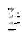
INCORRECT LOW BATTERY INDICATION
NO OR LOW DISPLAY
START
YES
IS PIN 4 OF U101
AT -9.6V ?
CHECK FOR BAD
SOLDER ON Q102
AFTER REPLACE IT.
NO
CHECK L500 ON PIN 6 OF
U101 AND POLARITY OF
C101, C102, C103. IF ANY
MENTIONED PROBLEM ARE
PRESENT REPLACE U101.
P18
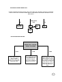
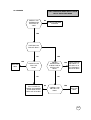
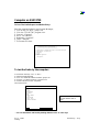
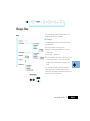
8700 PROCEDURE LVL3
START
DOES PCB
POWER UP
CORRECTLY.?
NO
ed. 1.1
PROCEED TO "WILL NOT POWERS
& STAY ON" ON PAGE 3
YES
YES
DOES PCB
DRAWS
CURRENT
WHEN IS OFF?
PROCEED TO "DRAWS CURRENT
WHEN IS OFF" ON PAGE 19
NO
DOES PCB
POWER DOWN
WHEN
TWISTED?
YES
PROCEED TO "POWER OFF
WHEN TWISTED" ON PAGE 8
NO
DOES WAKE
UP DISPLAY
CORRECT.?
NO
PROCEED TO "NO OR
LOW DISPLAY" ON PAGE
18
YES
PROCEED TO "PHONE
FAILURE SEE SUPPLIER" ON
PAGE 19
NO
PROCEED TO "NO
SERVICE AT -102dBm" ON
PAGE 12
YES
DOES DISPLAY
SHOW "PHONE
FAILURE SEE
SUPPLIER"?
NO
DOES PCB GO
INTO SERVICE
AT -102dBm?
YES
1
1
CAN PCB
INITIATE A
CALL TO THE
ANALYZER?
NO
PROCEED TO "WILL NOT
INITIATE A CALL" ON PAGE 9
YES
TERMINATE THE CALL
CALL MOBILE FROM
ANALYZER
IS RING AUDIO
TONE
AUDIBILE?
NO
PROCEED TO "NO OR LOW
RING TONE" ON PAGE 1
YES
ANSWER CALL.
IS THE TX FREQ
OR PHASE
ERROR WITHIN
SPEC.?
NO
PROCEED TO "FREQ ERR." OR
"PHASE ERROR OUT OF
SPEC." ON PAGE 8
YES
IS THE POWER
BURST WITHIN
SPEC.?
YES
2
NO
PROCEED TO "POWER BURST
OUT OF SPEC." ON PAGE 17
2
IS THE TX
AUDIO PATH
OK.?
NO
PROCEED TO "NO OR LOW
AUDIO VOLUME" ON PAGE 1
YES
IS AUDIO
LOOP-BACK
CORRECT.?
NO
PROCEED TO "NO OR LOW AUDIO
MICROPHONE" ON PAGE 2
YES
TERMINATE THE CALL
IS THE LOW
BATTERY
INDICATION
CORRECT.?
NO
PROCEED TO "INCORRECT LOW
BATTERY INDICATION"ON PAGE 18
YES
NO
DOES THE
CHARGER
FUNCTION
CORRECTLY?
YES
NO FAULT FOUND
PROCEED TO "NO
CHARGER" ON PAGE 20
PCB DRAWS CURRENT WHEN IS OFF
CHECK TRANSISTOR REGULATOR: Q202, Q203 AND U201 ARE NOT PHISCALLY
DAMAGE; CHECK ALSO U900 TO MONITORING WHICH COMPONENT BECOMING
WARMER AFTER REPLACE IT.
B+
P.A. MOD.
Q301.302
VREF. FROM
U900
U201
B+
Q202
U900
2.75V
Q203
2.75V
PHONE FAILED SEE SUPPLIER
ENTER 7100# , 7101# AND
REPORT THE CODES
04/XX
CHECK Q203 FOR RX
275: IF IS NOT
CORRECT REPLACE
Q203; IF IS CORRECT
REPLACE U501.
07/XX
TRY TO REFLEX U702
VIA EMMIBOX OR
MASTER CARD IF
STILL NOT CORRECT
SEND TO HI-TECH.
05/XX
ENTER 171# AND 57#
AND POWER UP THE
RADIO AGAIN. IF STILL
NOT CORRECT
CHECK FOR 26 MHz
FROM PIN 6 OF U805:
IF IS OK REPLACE
U801, IF IS NOT OK
REPLACE U805.
P19
NO CHARGER
TEST CONDICTION: RADIO SUPPLY FROM
EXT B+ AND IN TEST-MODE
CHECK 2.75V
THERMISTOR
ON PIN12 OF
J400?
NO
CHECK FOR Q604
DAMAGE
YES
CHECK 8V ON
PIN4 OF Q601?
NO
YES
YES
REPLACE
U900
ENTER
500255# AND
CHECK FOR
0V ON PIN 4
OF Q601?
CHECK 0V ON
PIN17 OF
U900?
NO
CHECK FOR 8V
ON PIN5.6.7.8.
OF Q601 IF IS
NOT CORRECT
REPLACE Q601.
NO
NO
TRY TO REFLEX
RADIO VIA MASTER
CARD AND AFTER
REPLACE U703 BIC.
YES
YES
CHECK 2.75V
ON PIN17 OF
U900?
REPLACE
U900
P20
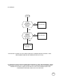
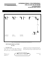
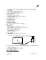
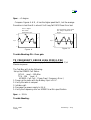
to U501, 42
217 Hz WAVEFORM NEEDED HERE !
5
10
14
MDM_WR
CALL
PROCESSOR
U701
15
SPI_RFCS
16
RF_START
C
E
ADDRESSS BUS
B
Q501
TX_ENABLE
TXD - to J400, 14
19
RXD - to J400, 14
1, 9, 36, 46
50, 52, 54
73, 108, 125
BATT_SENSE
4
D/A
A/D
34
33 38 40
39
DAC_OUT
68
1
46
EXT B+
via R910 / R911
BATT_FDBK
CR605
BIC_INT
J400
+ 2,75V
7, 19, 26, 50, 66
76, 85, 100
4
5
SPEECH CODER
U801
13
8
3
78
18
A/D
19
512 KHz
VERIFY THESE WAVEFORMS
1, 13, 15, 25, 26
51, 62, 75, 83, 94
8
DATA
1
2
J802
J2
1
D/A
VAG
4
21
20
+
MUX
3
19
+
5
4
-1
B+
V3
28
R+2.75V
DC - DC
V2
2, 7
FS_AUD
22
37
GCAP
U900
3
32, 41
L+2.75V
T900
VSWITCH3.85V
L500
R475
VSS
REVISIONS
RX SIGNAL WAY
TX SIGNAL WAY
REFERENCE CLOCK
7
4
MIC
9
-
DOUBLER
U805
37
E
6
3
47
CLK_AUD
33
6
Q905
Q999
17
ISENSE
10
39, 40
43, 48
8 KHz
X2 Multiplexer
CHARGER
-1
81
2
5
2
17
13
16
CODEC
U803
DIGITAL POT
U802
13_DCLK_B
1
Q602
6
5
26 MHz
C
J400
Q601
84
DOUBLER_EN
4
BATT+
R602
Encoded
Voice Data
45
E
Q906
B
10
15
SC_INT
B
C
2
B+
14
BATT_GND
BATT+
12
AD_THERM
UPLINK
(non-voiced data)
+ 2,75V
MF_INT
RX / TX
SIGNAL
PROCESSING
WARM SWITCH-OVER
CIRCUIT
U701, 19
EXT_B+
E
+2.75V
B
66
ADDRESSS BUS
DATA BUS
C
Q503
U703
BIC
DOWNLINK
(non-voiced data)
65
17
FLASH
U702
DATA BUS
ADDRESSS BUS
122
18, 40, 48
56, 69, 112, 126
B
C
9
57
67
PAC_ENABLE
EEPROM
U705
to U702, 26
2
+4.75V
Q504
35
17
37
DATA BUS
4
C
20
3
to U704, 39
ROM1CS
133
E
48
SRAM
U704
to U704, 40
RAM1CS
12
MDM_RD
RX_EN
RAM2CS
11
SPI_SCK
RESET
to J2, 8
to J2, 2
DP_EN
SPI_MO
RESET
to U702, 16
6
SPI_MI
to U501
DUAL_CS
+ 2,75V
EARPIECE
DM_CS
TX_KEY
13_DCLK_B
from U201, 59
120
51
123
ALERT
RX_ACQ
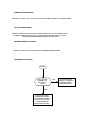
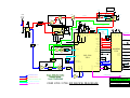
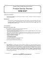
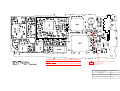
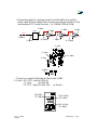
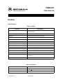
GSM 6700 / 8700: AL BLOCK DIAGRAM
Europe Middle East & Africa Customer Services
20.03.98
LEVEL 3 COLOUR DIAGRAMS
Rev. 1.0
Dual Band ZAP
Colin Jack, Michael Hansen, Billy Jenkins
Page 1 of 2
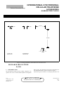
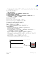
CH. 001 = 1.50Vdc
CH. 062 = 1.74 Vdc
CH. 124 = 1.87 Vdc
+2.75V
+4,75V
14
ANT
(+6dB)
(+15dB)
B
C
TWO STAGE
PA
B
C
TX
VCO
C
8
902,4 MHz
CHARGE
PUMP
Q381
Q302
9,10
7
U300
CR300
2 ,12
Q300
(+15dB)
D
RX 2.75
G
Q301
1
Supplies 13 MHz oscillator
PLL dividers & U501 DAC
references
DM_CS
+ 2.75V
4
TX_KEY
DET_SW
OFST_E 6
OFST_B 7
Vref from U900, 11
216 MHz
TXQ_M
TXQX 62
26 PRSC_IN
(- 3.5dBm)
TXI_P
TXI 63
MAIN VCO
TXIQ 64
CR 250
794,4 MHz (CH 062) Q251
Q252
51
GIF_SYN
U201
RX
LOCAL
OSCILLATOR
(- 3dB)
TANK
CIRCUIT
17
41 LO2_BASE
306MHz
(- 3.5dB)
C
Q418
E
FL452
B
C
FL420
Q420
153 MHz
59 CLK_OUT
(- 6dB)
31 PRE_IN
947,4 MHz (CH 62)
from U310, 12
to U310, 11
RX_ACQ
17
2, 5,10,18
25, 41, 44,
45, 53, 64, 70
B+
76
RXI 46
15
IQ_REF 47
16
6
RXQ 48
14
79
XTAL_BASE 57
+2,75V
MDM_RD
+4.75V
42 LO2_EMITTER
(+18dB)
(+9 dB)
MODEM
U501
75
11, 22, 44
RX 2.75V
B
DM_CS
9
RF_START
43 LO2_CP
FL453
from U701, 6
23
78
SPI_DATA 52
69
24
RF_SPI
LOOP FILTER
U310, 10
TX_KEY
22
77
SPI_CLK 53
RESET
21
RF_SCK
23 MAIN_CP
Q250
TXI_M
13_DCLK_B
from U703, 37
73
TXQ_P
TXQ 61
SUPER FILTER VOLTAGE 21 SF_OUT
FL 451
42
TANK
CIRCUIT
16
AOC_DRIVE
DET_SW 66
from Q504,3
AOC_OUT 33
8
IQ_FLT 1
10
TX
OFFSET
LOCAL
OSCILLATOR
OFST_CP 10
SAT_DET
RX_EN TX_EN
11
LIM_OUT 4
12
PAC
ENABLE
IQ FILTER
IQ_FLTX 2
4
E
B
REG_SPLY 17
DET
VSWITCH
SAT_DET 67
Supplies limitor amps
2nd LO, IF circuts&
references
V2_OUT 19
Q442
Q443
2
SW_RF
from J400,16
108 MHz
C
Q202
U310
5
3
SUPER
FILTER
6
E
B
MAIN_VCC 25
8
1, 3
7
VI_DRIVE 13
14
TX +4.5V
V2_DRIVE 18
2&7 1
to U310, 8
U400
33 SW_VCC
4
Q203
MAIN _VCO (794,4 CH 062)
C
Y201
AFC
29
8
4
MDM_WR
SPI_MI
SPI_RFCS
SPI_SCK
SPI_MO
(+7dB)
RX SIGNAL WAY
Q421
TX SIGNAL WAY
REFERENCE CLOCK
U703,17
REVISIONS
MAIN VCO SIGNAL WAY
TUNING VOLTAGES
13 MHz CLOCK
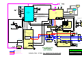
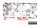
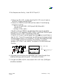
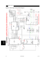
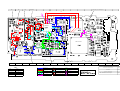
GSM 6700 / 8700: RF BLOCK DIAGRAM
Europe Middle East & Africa Customer Services
20.03.98
LEVEL 3 COLOUR DIAGRAMS
Rev. 1.0
Dual Band ZAP
Colin Jack, Michael Hansen, Billy Jenkins
Page 1 of 2
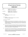
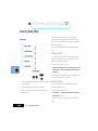
INTERNATIONAL 8700 PERSONAL
CELLULAR TELEPHONE
Module Level
Repair Manual
68P09304A68-O
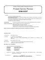
INTERNATIONAL 8700 CELLULAR TELEPHONE
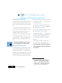
COMPUTER SOFTWARE COPYRIGHTS
The Motorola products described in this instruction manual may include copyrighted Motorola computer programs stored in semiconductor memories
or other media. Laws in the United States and other countries preserve for Motorola certain exclusive rights for copyrighted computer programs,
including the exclusive right to copy or reproduce in any form the copyrighted computer program. Accordingly, any copyrighted Motorola computer
programs contained in the Motorola products described in this instruction manual may not be copied or reproduced in any manner without the express
written permission of Motorola. Furthermore, the purchase of Motorola products shall not be deemed to grant either directly or by implication, estoppel,
or otherwise, any license under the copyrights, patents or patent applications of Motorola, except for the normal non-exclusive, royalty free license to
use that arises by operation of law in the sale of a product.
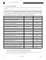
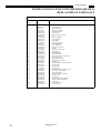
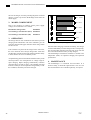
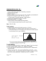
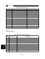
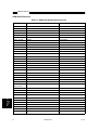
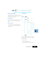
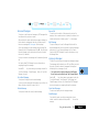
PERFORMANCE SPECIFICATIONS -INTERNATIONAL 8700 (GSM)
GENERAL
Frequency Range
Channel Spacing
Number of Channels
Modulation
Transmitter Phase Accuracy
Duplex Spacing
Frequency Stability
Voltage Operation
Transmit Current
Stand-by Current
Dimensions
Size (Volume)
Weight
Temperature Range
890-915 MHz Tx
935-960 MHz Rx
200 kHz
124 carriers with 8 channels per carrier
GMSK at BT = 0.3
5 Degrees RMS, 20 Degrees peak
45 MHz
+/- 0.10 ppm of the downlink frequency (Rx)
+5.7 to +8.5V dc
<199 mA average, 900mA peak
Average 10 mA (DRX 2)
131 mm (L) x 59 mm(W) x 24 mm(D) (5.2” x 2.3” x 0.9”)
173 cubic cm (10.6 cubic in)
Approximately 210g; Includes GP4 MiMH battery pack and antenna
-20°C to +55°×C
TRANSMITTER
RF Power Output
Output Impedance
Spurious Emissions
33 dBm
50 ohms (nominal)
-36 dBm up to 1 GHz, (<-30 dBm > 1 GHz)
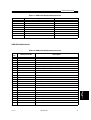
RECEIVER
RF Level
RX bit error rate (100 kbits)
Channel Hop Time
Time to Camp
-102 dBm
< 2%
500 microseconds
Approximately 10 seconds
SPEECH CODING
Speech Coding Type
Regular Pulse Excitation / Linear Predictive Coding with Long Term Prediction. (RPE
LPC with LTP.
Bit Rate
Frame Duration
Block Length
Classes
Bit Rate with FEC Encoding
13.0 kbps
20 ms
260 bits
Class 1 bits = 182 bits. Class 2 bits = 78 bits
22.8 kbps
Specifications subject to change without notice
CAUTION
Do not jump start vehicle or use an automotive battery charger while the vehicle adapter
option and the portable radiotelephone are connected to the vehicle electrical system as this
may cause serious damage to the radio. Disconnect the radio by removing the cable kit fuses.
ii
© Motorola Ltd. 1996
All Rights Reserved
Printed in U.K.
68P09304A68-OAGen1
1/6/96
Cellular Subscriber Group
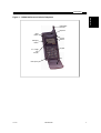
INTERNATIONAL 8700 PERSONAL
CELLULAR TELEPHONE
MODULE
LEVEL
68P09304A68-O
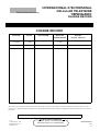
REPAIR RECORD
MANUAL
CHANGE
CHANGE RECORD
CHANGE
DATE
SIGNATURE
DATE OF
COMPLETION
O-Original
1/6/96
-
1/6/96
NOTES
(Section Affected)
When CMR’s are issued against this manual they are to be inserted in numerical order, then this record sheet should be annotated to confirm the action.
If there are any subsequent problems resulting then the ‘Documentation Feedback’ form should be completed and returned to address given. See section in
this manual.
Motorola reserves the right to make changes in technical and product specifications without prior notice
AGen1
© Motorola Ltd. 1996
All Rights Reserved
Printed in U.K.
Customer Services Publishing
Midpoint, Alencon Link, Basingstoke,
Hampshire, RG21 7PL, United Kingdom
68P09304A68-O
1/6/96
iii
INTERNATIONAL 8700 CELLULAR TELEPHONE
*
PAGE INTENTIONALLY BLANK
68P09304A68-OAGen1
iv
1/6/96
Cellular Subscriber Group
INTERNATIONAL 8700 PERSONAL
CELLULAR TELEPHONE
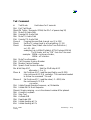
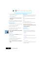
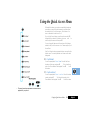
SECTION 1 - GENERAL
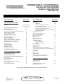
CONTENTS LIST
PAGE NUMBER
FOREWORD
MOTOROLA SERVICE POLICY
GENERAL SAFETY INFORMATION
EXPRESS EXCHANGE PROGRAM
INTRODUCTION
EQUIPMENT REQUIRED
EXCHANGE PROCEDURE
xi
xi
xii
1
1
1
1
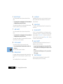
SECTION 2 - DESCRIPTION
SYSTEM DESCRIPTION
G.S.M. SYSTEM OVERVIEW
TELEPHONE DESCRIPTION
FEATURE LIST
3
3
6
9
SECTION 3 - LABELLING & SIM CARDS
TRANSCEIVER LABELLING
INTRODUCTION
TITLE EXPLANATIONS
SIM CARDS
INTRODUCTION
SIM CARD INSERTION/REMOVAL
SECURITY INFORMATION
11
11
11
13
13
13
13
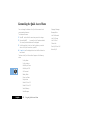
SECTION 4 - MANUAL - TEST MODE & VERIFICATION
MANUAL-TEST MODE
INTRODUCTION
TEST SIM INSERTION/REMOVAL
ACCESSING THE MANUAL-TEST MODE
AGen1
© Motorola Ltd. 1996
All Rights Reserved
Printed in U.K.
Customer Services Publishing
Midpoint, Alencon Link, Basingstoke,
Hampshire, RG21 7PL, United Kingdom
15
15
15
15
1/6/96
v
INTERNATIONAL 8700 CELLULAR TELEPHONE
SECTION 4 - MANUAL - TEST MODE & VERIFICATION (cont)
VERIFICATION
INTRODUCTION
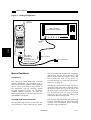
EQUIPMENT CONFIGURATION
TESTING PROCEDURE
PAGE NUMBER
17
17
17
18
SECTION 5 - TROUBLESHOOTING
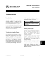
TROUBLESHOOTING
INTRODUCTION
TROUBLESHOOTING AND REPAIR
TESTING AFTER REPAIR
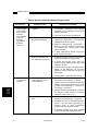
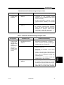
TROUBLESHOOTING AND REPAIR CHART
19
19
19
19
20
SECTION 6 - PERSONALITY TRANSFER
PERSONALITY TRANSFER
INTRODUCTION
NORMAL TRANSFER
MASTER TRANSFER
MASTER SIM CARD CREATION
23
23
23
24
24
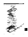
SECTION 7 - DISASSEMBLY
DISASSEMBLY INSTRUCTIONS
INTRODUCTION
RECOMMENDED TOOLS
DISASSEMBLY PROCEDURE
ASSEMBLY PROCEDURE
EXPLODED DIAGRAM AND PART NUMBERS
25
25
25
25
25
35
SECTION 8 - ACCESSORIES
RECHARGEABLE BATTERY PACKS
INTRODUCTION
RECHARGING
EXPERT PERFORMANCE BATTERIES AND CHARGERS
BUILT IN E.P BATTERY FAST CHARGER
68P09304A68-OAGen1
vi
1/6/96
37
37
37
38
38
CONTENTS
SSECTION 8 - ACCESSORIES (cont)
PAGE NUMBER
NICAD BATTERY PACKS
39
NI-MH BATTERY PACKS
41
LITHIUM ION BATTERY PACKS
43
TRAVEL BATTERY CHARGER
45
CIGARETTE LIGHTER ADAPTOR/CHARGER
47
INTELLICHARGE E.P BATTERY CHARGER
49
CAR KITS
INTRODUCTION
STANDARD DHFA
MICRO CAR KITS
HANDSFREE CAR KIT
INSTALLATION
53
53
53
53
53
53
SECTION 9 - GLOSSARY
GLOSSARY OF GSM TERMS
55
SECTION 10 - NOTES
FEED BACK FORM
NOTES
AGen1
1/6/96
57
59
68P09304A68-O
vii
INTERNATIONAL 8700 CELLULAR TELEPHONE
*
PAGE INTENTIONALLY BLANK
68P09304A68-OAGen1
viii
1/6/96
Cellular Subscriber Group
AGen1
© Motorola Ltd. 1996
All Rights Reserved
Printed in U.K.
INTERNATIONAL 8700 PERSONAL
CELLULAR TELEPHONE
Customer Services Publishing
Midpoint, Alencon Link, Basingstoke,
Hampshire, RG21 7PL, United Kingdom
MODULE LEVEL
REPAIR MANUAL
68P09304A68-O
1/6/96
ix
INTERNATIONAL 8700 CELLULAR TELEPHONE
TYPICAL MODEL COMPLEMENT FOR
INTERNATIONAL 8700 2.0 WATT S5634AAx
Model
Description
Quantity
Supplied
SUF3839A
Transceiver
1
SNN4612
SNN4458
Slim NiMH Battery
XT Li-Ion Battery
1
SPN4222A or
SPN4221A
Euro or
UK Transformer
1
SJN6549A SJN6555A
User Manual
1
68P09304A68-OAGen1
x
1/6/96
INTERNATIONAL 8700 CELLULAR TELEPHONE
FOREWORD
1. SCOPE OF MANUAL
2. MODEL AND KIT IDENTIFICATION
This manual is intended for use by experienced technicians
familiar with similar types of equipment. It contains all
service information required for the equipment described and
is current as of the printing date. Major changes which occur
after the printing date are incorporated by Cellular Manual
Revisions (CMR). These CMR’s are added to the manuals
as the engineering change is incorporated into the equipment.
Motorola equipments are specifically identified by an overall
model number on the nameplate. In most cases, assemblies
and kits which make up the equipment also have kit model
numbers stamped on them. When a production or
engineering change is incorporated, the applicable schematic
diagrams are updated.
MOTOROLA SERVICE POLICY (8700)
In most countries Motorola will operate an Express Exchange Program for the 8700 personal cellular telephone. Authorized
Express Exchange Centres will exchange a customer’s defective unit for a refurbished unit (if the defective unit is covered
by warranty, and has not been damaged or opened by the customer). The Express Exchange Centre must write the
mechanical serial number of the customer’s original unit on the warranty label of the exchange unit’s housing. This ensures
that when a customer returns a unit, the Express Exchange Centre can verify whether a customer is entitled to warranty.
Motorola National Support Centres will log and track units by the typed mechanical serial number on the approval label,
which will always remain on the phone.
Motorola National Support Centres may also act as Express Exchange Centres, and hold a quantity of exchange units.
This pool of exchange units may be used for “quick turnaround” emergency support to Express Exchange Centres which
have become short of replacement units.
The defective units will be returned initially to the National Support Centres, HUB’s, or their nominated and approved
Cellular Service Centres. Service Centres will be responsible for performing level 2 repairs. If it is found that the problem
is localised to the PCB then, in the case of an approved Cellular Service Centre, the unit will be sent to a National Support
Centre or HUB.
Product Service training should be arranged through the local Motorola National Support Centre.
REPLACEMENT PARTS ORDERING
ORDERING INFORMATION
Only centres authorized by Motorola to carry out repairs will be able to purchase spare parts. Orders for spare parts from
HUB’s, Motorola National Support Centres and Hi-Tech Centres, should be placed with the appropriate Motorola Parts
Distribution Centre.
BOARD REPAIRS
All centres authorized to carry out module level repairs, must return faulty boards to the appropriate HUB or Motorola
Hi-Tech Centre for repair to component level.
68P09304A68-OAGen1
xi
1/6/96
CONTENTS
GENERAL SAFETY INFORMATION
PORTABLE OPERATION:
DO NOT hold the radio so that the aerial is very close to, or touching, exposed parts of the body, especially the
face or eyes whilst transmitting. The radio will perform best if it is held in the same manner as you would hold
a ‘land’ telephone handset, with the aerial angled up and over your shoulder.
DO NOT operate the portable phone in an aircraft. Switch off your telephone. The use of a cellular telephone
in an aircraft may be dangerous to the operation of the aircraft, disrupt the Cellular Network, and is illegal.
Failure to observe this instruction may lead to a suspension or denial of Cellular Telephone Service to the
offender, or legal action, or both.
MOBILE/PORTABLE OPERATION - Telephone use in Vehicles:
All equipment must be properly grounded according to installation instructions for safe operation.
Users are advised to turn off their equipment when at a refuelling point.
Safety is every drivers business. Cellular telephones should only be used in situations in which the driver
considers it safe to do so.
GENERAL:
DO NOT allow children to play with any radio equipment containing a transmitter.
DO NOT operate this equipment near electrical blasting caps or in an explosive atmosphere. Mobile telephones
are, under certain conditions, capable of interfering with blasting operations. When you are in the vicinity of such
work, look out for and observe signs cautioning against mobile radio transmission. If transmission is prohibited,
you must turn off your mobile telephone to prevent any transmission.
In standby mode the mobile telephone will automatically transmit to acknowledge a call if it is not turned off.
Refer to the appropriate section of the product user manual for additional pertinent safety information
All equipment should be serviced only by a qualified technician.
AGen1
1/6/96
68P09304A68-O
xii
Cellular Subscriber Group
INTERNATIONAL 8700 PERSONAL
CELLULAR TELEPHONE
EXPRESS EXCHANGE
TM
PROGRAM
EXPRESS EXCHANGE
1.
INTRODUCTION
The basis of Motorola’s Express Exchange TM program is
that when a customer’s unit becomes defective, its
programming information is transferred into a fully
functional exchange phone. The exchange phone is then
given to the customer, allowing the customer to continue
using the same type of cellular telephone, without having to
worry about the length of the repair process.
2.
Step 1.
Select an exchange unit, which should be the
same model as the defective unit.
Step 2.
Transfer the personality of the customer’s
defective telephone into the exchange unit. See
page 21 of this manual for further details.
Step 3.
When the personality transfer has been
completed successfully, insert the customer’s
SIM card into the exchange unit. See page 11, for
further details on SIM card insertion.
Step 4.
With the SIM card in place, power up the
exchange telephone. Place a call to confirm that
the unit is functioning correctly.
Step 5.
Write the mechanical serial number of the
customers original unit on the warranty label of
the exchange unit, positioned above the type
approval label on the rear housing. Then give the
exchange phone to the customer.
Step 6.
Return the defective unit to the nearest Motorola
HUB or Authorized Repair Centre for repair.
Note that full component level repair is carried
out at Motorola Hi Tech Centres only.
EQUIPMENT REQUIRED
The following items are required for the exchange process
to be possible:•
Exchange cellular telephone (same as customer’s
unless multi bezel phones are being supported).
•
Charged battery pack.
•
Full size transfer SIM card.
•
Full size master transfer SIM card.
3.
EXCHANGE PROCEDURE
The following steps must be carried out when exchanging a
defective International 8700 personal cellular telephone (if
covered by warranty) for a fully functional exchange unit.
BDesc2
© Motorola Ltd. 1996
All Rights Reserved
Printed in U.K.
Customer Services Publishing
Midpoint, Alencon Link, Basingstoke,
Hampshire, RG21 7PL, United Kingdom
68P09304A68-O
1/11/94
1
INTERNATIONAL 8700 CELLULAR TELEPHONE
*
PAGE INTENTIONALLY BLANK
68P09304A68-O
2
BDesc2
1/6/96
Cellular Subscriber Group
INTERNATIONAL 8700 PERSONAL
CELLULAR TELEPHONE
DESCRIPTION
GENERAL
SYSTEM DESCRIPTION
1.
1.2
G.S.M. DESCRIPTION
G.S.M. SYSTEM OVERVIEW
NOTE
The following description is intended only as a
preliminary general introduction to the Global
System for Mobile communications (G.S.M.)
cellular network. This description is greatly
simplified and does not illustrate the full operating
capabilities,
techniques,
or
technology
1.1
GENERAL CELLULAR CONCEPT
The cellular systems are used to provide radiotelephone
service in the frequency range 890-960 MHz. A cellular
system provides higher call handling capacity and system
availability than would be possible with conventional
radiotelephone systems (those which require total system
area coverage on every operating channel) by dividing the
system coverage area into several adjoining sub-areas or
cells.
Each cell contains a base station (cell site) which provides
transmitting and receiving facilities, for an allocated set of
duplex frequency pairs (channels). Since each cell is a
relatively small area, both the cell site and the radiotelephone
that it supports can operate at lower power levels than would
be used in conventional systems. Using this technique,
radiation on a given channel is virtually contained in the cell
operating on that channel and, to some extent, those cells
directly adjacent to that cell.
Since the coverage area of a cell on a given channel is limited
to a small area (relative to the total system coverage area), a
channel may be reused in another cell outside the coverage
area of the first. By this means, several subscribers may
operate within the same geographic area, without
interference with each other, on a single channel.
BDesc2
© Motorola Ltd. 1996
All Rights Reserved
Printed in U.K.
Customer Services Publishing
Midpoint, Alencon Link, Basingstoke,
Hampshire, RG21 7PL, United Kingdom
68P09304A68-O
1/6/96
3
INTERNATIONAL 8700 CELLULAR TELEPHONE
Refer to Figure 1. In the figure, the area bounded by bold
lines represents the total coverage area of a hypothetical
system. This area is divided into several cells, each
containing a cell site (base station) operating on a given set
of channels which interfaces radiotelephone subscribers to
the telephone switching system.
E
B
A
CHANNELS
D
By incorporating Time Division Multiple Access (TDMA)
several calls can share the same carrier. The carrier is divided
into a continuous stream of TDMA frames, each frame is
split into eight time slots. When a connection is required the
system allocates the subscriber a dedicated time slot within
each TDMA frame. User data (speech/data) for transmission
is digitized and sectioned into blocks. The user data blocks
are sent as information bursts in the allocated time slot of
each TDMA frame, see Figure 2. The data blocks are
modulated onto the carrier using Gaussian Minimum Shift
Keying (GMSK), a very efficient method of phase
modulation.
CHANNELS
USER DATA SECTIONED INTO BLOCKS
CHANNELS
C
CHANNELS
CHANNELS
F
CHANNELS
INFORMATION BURSTS SENT IN ALLOCATED TIME SLOTS
0 12 3 4 5 6 7 0 12 3 4 5 6 7 0 12 3 4 5 6 7 0 12 3 4 5 6 7
FRAME 0
Figure 1. Hypothetical Cell System
FRAME 2
FRAME 3
Figure 2. Time Division Multiple Access Transmission
The radiotelephones themselves are capable of operation on
any channel in the system, allowing them to operate in any
cell. Due to the low power requirements for communications
between radiotelephones in a particular cell and the cell site,
operating channels may be repeated in cells which are outside
the coverage area of each other.
For example, presume that cell A operates on channels
arbitrarily numbered 1 through 8, cell B operates on channels
9 through 16, cell C operates on channels 17 through 24 and
cell D operates on channels 1 through 8 (repeating the usage
of those channels used by cell A). In this system, subscribers
in cell A and subscribers in cell D could simultaneously
operate on channels 1 through 8. The implementation of
frequency re-use increases the call handling capability of the
system, without increasing the number of available channels.
When re-using identical frequencies in a small area, cochannel interference can be a problem. The G.S.M. system
can tolerate higher levels of co-channel interference than
analogue systems, by incorporating digital modulation,
forward error correction and equalization. This means that
cells using identical frequencies can be physically closer,
than similar cells in analogue systems. Therefore the
advantage of frequency re-use can be further enhanced in a
G.S.M. system, allowing greater traffic handling in high use
areas.
Each time an information burst is transmitted, it may be
transmitted on a different frequency. This process is known
as frequency hopping. Frequency hopping reduces the effects
of fading, and enhances the security and confidentiality of
the link. A G.S.M. radiotelephone is only required to transmit
for one burst in each frame, and not continually, thus enabling
the unit to be more power efficient.
Each radiotelephone must be able to move from one cell to
another, with minimal inconvenience to the user. The mobile
itself carries out signal strength measurements on adjacent
cells, and the quality of the traffic channel is measured by
both the mobile and the base station. The handover criteria
can thus be much more accurately determined, and the
handover made before the channel quality deteriorates to the
point that the subscriber notices.
When a radiotelephone is well within a cell, the signal
strength measured will be high. As the radiotelephone moves
towards the edge of the cell, the signal strength and quality
measurement decreases. Signal information provides an
indication of the subscriber’s distance from the base station.
As the radiotelephone moves from cell to cell, its control is
handed from one base station to another in the new cell. This
change is handled by the radiotelephone and base stations,
and is completely transparent to the user.
68P09304A68-O
4
FRAME 1
BDesc2
1/6/96
DESCRIPTION
1.3
SERVICE AREA
The area within which calls can be placed and received is
defined by the system operators. (Because this is a radio
system, there is no exact boundary that can be drawn on a
map.) If the telephone is outside a coverage area, the (no
service) indicator will illuminate and calls will be unable to
be placed or received. If this happens during a conversation,
the call will be lost. There may also be small areas within a
particular service area where communications may be lost.
The radiotelephone’s identity information is held by its local
G.S.M. system in its Home Location Register (HLR) and
Visitor Location Register (VLR). The VLR contains identity
information on all local active radiotelephones. Should you
roam to another area, system or country the radiotelephones
identity information is sent to the VLR in the new system.
The new system will then check the radiotelephones details
with your home system for authenticity. If everything is in
order it will be possible to initiate and receive calls whilst in
the new area.
RETRACTABLE
ANTENNA
EARPIECE
VOLUME
BUTTONS
MUTE
BUTTON
SIM
EJECT
BUTTON
32 X 96 PIXEL
LCD DISPLAY
KEYPAD
FLIP
MICROPHONE
Figure 3. International 8700 Personal Cellular Telephone.
BDesc2
1/6/96
68P09304A68-O
5
INTERNATIONAL 8700 CELLULAR TELEPHONE
2.
CELLULAR PERSONAL
TELEPHONE DESCRIPTION
2.1
GENERAL
Grounding shields on the main board provide electrical
isolation and protection to the RF circuits. Interconnection
between the two main boards takes place via a 41 pin female
connector situated on the display board, and a corresponding
male connector on the main board.
The International 8700 personal cellular telephone (shown
on previous page, in Figure 3) is a microprocessor controlled,
full duplex, synthesized FM radiotelephone using digital
modulation techniques, for use in compatible 900 MHz
cellular radiotelephone systems. When operated properly,
the equipment will provide the user with land-linked
telephone service through individual cell site base stations,
all linked to a central control office. The International 8700
has a 2.0 Watt maximum output power capability.
2.2
Operating power for the personal telephone can be obtained
from various methods including the following:1/.
This rechargeable Lithium Ion battery pack is the lightest
Motorola battery offered for the International 8700.
2/.
The Super Slim Battery NiCad (SNN4467).
3/.
The Ultra Slim Battery NiCad (SNN4132).
4/.
The Ultra Slim Battery NiMH (SNN4283).
5/.
The Slim XT Battery NiCad (SNN4102).
6/.
The Standard Battery NiCad (SNN4027).
7/.
The Standard XT Battery NiMH (SNN4259).
8/.
The Cigarette Lighter Adaptor (SLN9933).
PHYSICAL PACKAGING
The transceiver circuitry is contained in a water resistant
polycarbonate plastic housing measuring (including Slim
battery pack) 131 mm (L) x 59 mm (W) x 24 mm (D) (5.2”
x 2.3” x 0.9”). It weighs approximately 214g; includes Slim
NiMH battery pack and antenna.
The main internal electronic circuitry is contained on two
multi-layer boards. The keypad board assembly incorporates
the display, keypad contacts and mylar switches, alert
transducer, vibrator and earpiece speaker. The display is
glued to the board by a foam gasket with electrical
connections via a short flex strip. Also on the keypad board
are the contacts for the SIM card, the mute and volume button
contacts, the SIM card presence switch, and the magnetic
reed switch.
The RF/Logic board is divided into two sections. The top
half of the board (antenna end), has the RF circuitry located
on both sides of the board. Similarly, the Audio/Logic
circuitry is located on both sides of the lower half of the board
(accessory connector end). Electrical connections between
the two sides of the board are provided by feed-through
connectors at various points on the board. Also on the main
board are the accessory connector, the battery contacts and
the microphone plug socket. The microphone and grommet
sits in a small pocket in the front housing and connects to the
main board via two wires terminated in a plug.
The accessory connector, situated at the base of the phone
on the main board, allows connections to the audio/logic
circuitry and antenna for accessory applications such as a
mobile adaptor and chargers. When the accessory RF
connector is used (ie terminated with a resistance of
approximately 10 Kohms or less to ground) the RF to the top
antenna is disconnected.
The battery charger plugs into the accessory connector
socket, situated at the base of the telephone, and a vehicle’s
cigar lighter socket. As well as providing a battery charging
function, the adaptor provides power directly to the phone
whilst it is in use even with a ‘dead’ battery.
9/.
Vehicle Adaptor Kits.
There are various vehicle adaptor kits available. They all
provide power to the unit from the vehicle’s own electrical
system, via the accessory connector socket (located at the
base of the phone). All the kits offer battery charging as
standard.
10/.
Travel Battery Charger
This is a mains adaptor which plugs directly into the phone.
It charges the phone’s battery whilst attached and also
provides dead battery operation.
NOTE: The International 8700 may have various battery
options as standard depending on the particular market
requirements.
68P09304A68-O
6
The Super Slim Battery Lithium (SNN4383).
BDesc2
1/6/96
INTERNATIONAL 8700 PERSONAL
CELLULAR TELEPHONE
Cellular Subscriber Group
PRODUCT DESCRIPTION
FEATURE LIST
FEATURE LIST
PRESENT
VISUAL/AUDIO FEATURES
Display
32 X 96 Pixel
Graphics Display
Number Capacity (per location)
20
Name Capacity (per location)
16
Language Selection
14
Automatic Language Selection based on SIM
X
Silence Ringer w/Visual
X
Silence Keypad Tones
X
Adjustable earpiece volume
X
Adjustable ringer volume
X
Silence Scratchpad
X
Call in Absence Indicator
X
Display Signal Strength - continuous
X
Display Battery Level - continuous
X
Audible Low Battery Warning
X
Status Review
X
Microphone Mute
X
Illuminated Display
X
Backlight Display
X
Dedicated Control Keys
7
User Definable Wake Up Test
X
CALL PLACEMENT FEATURES
VibraCall Alert
Selectable Ringer Tones
Selectable Keypad Tones
Short, Extended and Personalised Menu List
Auto Redial
Clear Last Digit/All
Mute Control
International Access Key Sequence
User Call Rejection
Pre-origination Dialling
X
X
X
X
X
X
X
X
X
X
FEATURE LIST
PRESENT
Memories:
Numbered
SIM Card - Dependent on SIM
Last 10 Numbers Dialed
Last 10 Numbers Received (if using CLI)
Notepad (Last Number Entered)
Turbo Dialling (9 Numbers 1 Touch Dial)
from Phone and SIM
Alpha Name Storage
Recall by Name or Location
Memory Linking/Pause
Memory Auto Load
Memory Scroll
Alpha Name Scrolling
Memory Capacity
DTMF Signalling:
Long Tone DTMF
DTMF from Memory
Postscripting
Menu Operation
Silent Alert
Call Diverting/Barring (Via the Menu)
Calling Line Identification (Present and Restrict)
Call Waiting
Call Hold
Master Clear
Master Reset
DTX (Discontinuous Transmission)
112 Emergency Call Origination
100
X
X
X
X
X
X
X
X
X
X
X
X
X
X
X
X
X
X
X
X
X
X
X
X
X
COST CONTROL FEATURES
Electronic Lock
Automatic Lock
Programmable Unlock Code
Display Unlock Code
X
X
X
X
An ‘X’ indicates that the feature is present in the International 8700
BDesc2
© Motorola Ltd. 1996
All Rights Reserved
Printed in U.K.
Customer Services Publishing
Midpoint, Alencon Link, Basingstoke,
Hampshire, RG21 7PL, United Kingdom
68P09304A68-O
1/11/94
7
INTERNATIONAL 8700 CELLULAR TELEPHONE
FEATURE LIST
PRESENT
COST CONTROL FEATURES (cont.)
Display Call Timers and/or Charge Meters:
Last Call
Total
Home
Roam
Programmable Audible Call Timer
One Time
Repeatable (User Defined)
Automatic Timer Display:
Charge (units/currency)
Minutes
Store Charge Rate:
Home Rate
Roam Rate
Call Restriction Levels:
Restrict Keypad Dialing
Variable Memory Recall Restriction
Restrict Incoming Calls
Restrict Phone Number Length (Vari)
Full Service-No Restrictions
PIN Entry
PIN Enable/Disable
PIN Change
PIN Unblocking
X
X
X
X
X
X
X
X
X
X
X
X
X
X
X
X
X
X
X
NETWORK RELATED
Service Selection:
Auto PLMN Selection
PLMN Select from Scan List
Scan List Display (auto and manual)
X
X
X
FEATURE LIST
Change Preferred List
Rearrange Order of Preferred List
Full Size SIM card
Display Own Phone Number
PRESENT
X
X
X
X
MESSAGING AND DATA
SMS:
Mobile Originated
Create/send/store/edit/view/delete
Mobile Terminated Point to Point
Cell Broadcast
Data Calls
X
X
X
X
X
VEHICULAR FEATURES
On Hook Call Processing
Volume Adj-Speaker
Safety Timer
Full Duplex Hands Free Operation
Ignition Sense (Auto Turn On)
Entertainment Mute
Auto Answer
X
X
X
X
X
X
X
OTHER FEATURES
Status Indicators
Easy Battery Removal
Internal Charger
Dead Battery Operation with Chargers
Rapid Charger
Cigarette Lighter Charger (Option)
X
X
X
X
X
X
An ‘X’ indicates that the feature is present in the International 8700
68P09304A68-O
8
BDesc2
1/6/96
Cellular Subscriber Group
INTERNATIONAL 8700 PERSONAL
CELLULAR TELEPHONE
TRANSCEIVER LABELLING
1.
INTRODUCTION
LABELLING AND SIM CARDS
TRANSCEIVER LABELLING
If the main board is replaced then the units IMEI will change,
therefore the units labelling should be updated with the new
IMEI. An IMEI uniquely identifies a mobile station
equipment to the system, and is divided into the sections
shown in Figure 2.
Each Motorola GSM transceiver will be labelled with
various number configurations. The following information
shows and explains the common labelling titles.
2.
2.1
IMEI 15 digits
TITLE EXPLANATIONS
2 digits
6 digits
TAC
FAC
SNR
SP
Serial
Number
Spare
Type
Approval
Code
MSN
The Mechanical Serial Number (MSN) is an individual
number, uniquely identifying the unit. The MSN will remain
the same throughout the units life, even if the main board is
replaced. Because the MSN is unique to the whole phone, it
is often used for logging and tracking purposes by Motorola
National Service Centres on EPPRS. The MSN is divided
into the sections shown in Figure1.
MSN 10 digits
3 digits
MC
Model
Code
1 digit
OC
Origin
Code
2 digits
DC
Date
Code
4 digits
Final
Assembly
Code
1 digit
Figure 2. IMEI Configuration
2.3
REV S/H
This configuration consists of two blocks of two digits, and
denotes the software and hardware versions within the unit.
The first two digits correspond to the software version, and
the last two digits correspond to the hardware version. If a
version update is carried out on the unit, the corresponding
change information should be made apparent on the
labelling.
SNR
Serial
Number
Figure 1. MSN Configuration
2.4
MODEL
The model number defines the type of product. Each product
type is issued a common model number.
2.5
2.2
6 digits
PACKAGE
CEPT GSM
This is the International Mobile Station Equipment Identity
(IMEI) number. The IMEI is held in the logic circuitry.
CLbl3
© Motorola Ltd. 1996
All Rights Reserved
Printed in U.K.
The package number is used to determine the type of
equipment, the mode in which it was sold, and the language
with which it was shipped.
Customer Services Publishing
Midpoint, Alencon Link, Basingstoke,
Hampshire, RG21 7PL, United Kingdom
68P09304A68-O
1/6/96
9
INTERNATIONAL 8700 CELLULAR TELEPHONE
*
PAGE INTENTIONALLY BLANK
68P09304A68-O
10
CLbl3
1/6/96
Cellular Subscriber Group
INTERNATIONAL 8700 PERSONAL
CELLULAR TELEPHONE
LABELLING AND SIM CARDS
SIM CARDS
SIM CARDS
1.
INTRODUCTION
The Motorola International 8700 personal cellular
telephones are designed to work with the full size Subscriber
Identity Module (SIM). The SIM card contains all the
personal data required to access GSM services. Data held by
the SIM card includes:•
•
•
•
•
•
International Mobile Subscriber Identity
Temporary Mobile Subscriber Identity
Home system
Services subscribed to
PIN and unblocking codes
Call barring codes
The SIM card may also be capable of storing phone
numbers, names, and messages.
2.
SIM CARD INSERTION/REMOVAL
The SIM card must be inserted into the unit correctly so that
the card can be read, and the data checked for validity,
before operation on the system will be enabled. The card
contains all of the user’s personal identification numbers
and details of the system the phone operates on.
SIM CARD SLOT
TEST SIM CARD
FLIP ASSEMBLY
INTERFACE
CONTACTS
The sliding, card release button will move upwards as the
SIM card is inserted. When the button reaches the top of its
recess and the card is flush with the base of the phone, it is
inserted correctly. To remove the SIM card from the unit,
push the sliding SIM card release button downwards. The
card will then be pushed out far enough to allow complete
removal. The User Guide contains full information about
inserting and removing the SIM card.
3.
SECURITY INFORMATION
To stop unauthorized personnel using your SIM card, the
option of using a Personal Identity Number (PIN) is
available. When enabled the option requires (on power up) a
verification number to be entered via the unit’s keypad,
before the card can be used. Three attempts to enter the
correct PIN may be made. If after the three entries the correct
PIN has not been entered, the card becomes blocked. To
unblock the card an unblocking/super PIN code must be
entered. Ten attempts to enter the correct unblocking code
are permitted, if after ten attempts the correct code has not
been entered, the SIM card is corrupted and becomes useless.
Another option available for the SIM card is call barring. If
subscribed to, the call barring of incoming and/or outgoing
calls may be accomplished by entering a special key
sequence. The key sequence includes a “barring code”,
which determines the type of restriction incorporated, and a
password to validate the request. The initial password is
provided when you subscribe to the service. The password
can be changed by entering a set key sequence.
A valid standard sized SIM card can be used in any working
GSM transceiver, regardless of the manufacturer, which is
compatible with the standard size SIM card. To protect the
actual unit from unauthorized use, a lock function on the
hardware is available. When enabled, this function requires
that a three or four digit unlock code be entered, via the unit’s
keypad, before normal operation of the transceiver can take
place. The lock code can be changed by entering a set key
sequence.
Figure 1. Inserting the Test SIM card
The whole SIM card should slide completely and securely
into the slot at the base of the phone. Ensure that the contacts
of the card face towards the front of the phone i.e. towards the
flip.
CLbl3
© Motorola Ltd. 1996
All Rights Reserved
Printed in U.K.
Note: Further information on set key sequences can be
derived from the unit’s user guide.
Customer Services Publishing
Midpoint , Alencon Link,
Basingstoke, RG21 7PL, United Kingdom
68P09304A68-O
1/6/96
11
INTERNATIONAL 8700 CELLULAR TELEPHONE
*
PAGE INTENTIONALLY BLANK
68P09304A68-O
12
CLbl3
1/6/96
Cellular Subscriber Group
International 8700 PERSONAL
CELLULAR TELEPHONE
MANUAL-TEST MODE & VERIFICATION
MANUAL-TEST MODE
MANUAL-TEST MODE
3.
INTRODUCTION
The Motorola International 8700 personal cellular
telephones are equipped with a manual-test mode capability.
This capability allows service personnel to take control of
the telephone, and by entering certain keypad sequences,
make the telephone perform desired functions. To enter the
manual-test mode, a Test SIM card (Part No 8102430Z01)
is required.
4.
TEST SIM CARD INSERTION
REMOVAL
The Test SIM card must be inserted into the unit correctly to
access manual-test mode. The whole SIM card should slide
completely and securely into the slot at the base of the
phone. Ensure that the contacts of the card face towards the
front of the phone i.e. towards the flip.
The sliding, card release button will move upwards as the
SIM card is inserted. When the button reaches the top of its
recess and the card is flush with the base of the phone, it is
inserted correctly. To remove the SIM card from the unit,
push the sliding SIM card release button downwards. The
card will then be pushed out far enough to allow complete
removal.
The User Guide contains full information about inserting
and removing the SIM card.
5.
ACCESSING THE MANUAL-TEST MODE
When the Test SIM card is in place, power up the telephone.
Once the initial automatic ‘wake up’ sequence has taken
place correctly, depress the # key (on the units keypad) for
three seconds. After three seconds ‘TEST’ should appear in
the display, indicating that the unit is now in the manual-test
mode. Table 1 below shows the available manual-test
commands and their corresponding results.
Command
SIM CARD SLOT
TEST SIM CARD
FLIP ASSEMBLY
INTERFACE
CONTACTS
Table 1
Result
01#
Exit manual-test mode
19#
Display call processor s/w version
20#
Display modem s/w version
22#
Display speech coder s/w version
57#
Initialize non-volatile memory
58#
Display security code
58xxxxxx#
Change security code
59#
Display lock code
59xxx#
Change lock code
60#
Display International Mobile station
Equipment Identity (I.M.E.I.)
Figure 1. Inserting the Test SIM card
Note: If a customer should forget the security code in their
unit, it can only be read or changed by using a Test SIM
card.
DTest4
© Motorola Ltd. 1996
All Rights Reserved
Printed in U.K.
Customer Services Publishing
Midpoint, Alencon Link, Basingstoke,
Hampshire, RG21 7PL, United Kingdom
68P09304A68
1/12/96
13
8700 CELLULAR TELEPHONE
*
PAGE INTENTIONALLY BLANK
68P09304A68
14
DTest4
1/12/96
Cellular Subscriber Group
International 8700 PERSONAL
CELLULAR TELEPHONE
MANUAL-TEST MODE & VERIFICATION
VERIFICATION
SMA
CONNECTOR
ANTENNA
TEST ADAPTOR
(0109354C01)
G.S.M. COMPATIBLE
COMMUNICATIONS ANALYSER
RF IN/OUT
PORT
i
OK
C
1
2
3
4
5
6
7
8
9
0+
UNIT TO
BE TESTED
Figure 1: Testing Configuration
VERIFICATION
1.
2.
INTRODUCTION
To test an International 8700 cellular telephone, to verify
whether or not the unit is functioning correctly, the
following equipment will be required:• G.S.M. compatible communications analyser.
• Test adaptor (Part No 0109354C01), and appropriate
cable/connectors.
• Test SIM card (Part No 8102430Z01).
EQUIPMENT CONFIGURATION
Initially insert the test SIM card into the slot at the rear of the
personal cellular telephone. If required, further information
on SIM card insertion is available on page 13. Attach the
antenna adaptor to the antenna connector of the phone. Slide
a charged battery on to the back of the personal telephone,
so that the telephone can be powered up. Finally, connect a
cable from the test adaptor to the RF in/out port of the
communications analyser, and power both the analyser and
personal telephone on. The equipment set up shown in
Figure 1 should now be in place.
• Charged battery pack.
DTest4
© Motorola Ltd. 1996
All Rights Reserved
Printed in U.K.
Customer Services Publishing
Midpoint, Alencon Link, Basingstoke,
Hampshire, RG21 7PL, United Kingdom
68P09304A68
1/12/96
15
8700 CELLULAR TELEPHONE
3.
TESTING PROCEDURE
All information required to perform the desired tests and measurements should be obtained from the communication analyser’s
user manual.
Ensure that the unit being tested is capable of both initiating a call to the analyser, and receiving a call from the analyser.
Confirm that the displayed Temporary Mobile Subscriber Identity (TMSI), International Mobile Equipment Identity (IMEI),
and dialled number are correct. When a call is in progress the following tests should be carried out on channels 1, 62 and
124. The recorded results must be within the acceptable stated limits, if the unit being tested passes all the tests it should be
taken as functioning correctly. If the unit being tested fails to conform with any of the expected measurements, it should be
taken as faulty and repaired accordingly. The following table states the required tests and tolerances.
TEST TO BE PERFORMED
LOWER LIMIT
UPPER LIMIT
Transmit average phase error (RMS) at peak power
5
Transmit average phase error (Peak) at peak power
20
Transmit average frequency error at peak power
-90 Hz
+90 Hz
Transmit power error at level 5 (33 dBm) 4
-2 dB
+2 dB
Transmit power error at level 7 (29 dBm) 4
-2 dB
+2 dB
Transmit power error at level 10 (23 dBm)4
-3 dB
+3 dB
Transmit power error at level 15 (13 dBm)4
-3 dB
+3 dB
Transmit amplitude negative peak flatness
-1 dB
Transmit amplitude positive peak flatness
+1 dB
Transmit amplitude envelope at -28 us
-70 dB
Transmit amplitude envelope at -18 us
-30 dB
Transmit amplitude envelope at -10 us
-6 dB
Transmit amplitude envelope at 556 us
-6 dB
Transmit amplitude envelope at 564 us
-30 dB
Transmit amplitude envelope at 574 us
-70 dB
Receive Bit Error Test for Class II Residual (at -102 dBm)4
2%
Receive Frame Erasure Rate for RES II (at -102 dBm)4
0.12%
Note: 1. The transmit average test values should be derived from 10 separate readings.
2. The receive signal strength for transmit measurements should be -85 dBm.
3. The receive test values should be derived from the reception of 20K bits of data.
4. There is approximately 1.8dB loss between the antenna port and the RF SMA connector on the test adaptor. The test
specifications are written for the power levels AT THE ANTENNA.
68P09304A68
16
DTest4
1/12/96
Cellular Subscriber Group
INTERNATIONAL 8700 PORTABLE
CELLULAR TELEPHONE
TROUBLESHOOTING
ASSEMBLY REPLACEMENT LEVEL
TROUBLESHOOTING
2.
1.
The troubleshooting information in Table 1 shows some
typical malfunction symptoms and the corresponding
verification and repair procedures. Refer to the disassembly
instructions located in the disassembly section of this manual
for instructions on removing and replacing parts/assemblies
from the personal telephone. If the Logic/RF assembly is
replaced a personality transfer will be necessary, see page 21
for more information.
INTRODUCTION
Assembly replacement level troubleshooting and repair of an
International 8700 personal telephone is limited to isolation
and replacement of the following main items only:•
Antenna
•
Battery
•
Logic/RF Assembly
•
Keypad/Display Board
•
Front/Rear Housings
•
Keypad Membrane
•
Earpiece Speaker
•
Microphone Transducer
•
Alert Transducer
NOTE
Defective Logic/RF assemblies must be replaced
with pre-tested, pre-phased assemblies.
3.
If at any time the unit is disassembled, whether repaired or
not, it is recommended that a simple test of making a call and
checking signal strength and transmit and receive audio
quality is carried out. Appropriate action should then be taken
on the outcome of the test.
© Motorola Ltd. 1996
All Rights Reserved
Printed in U.K.
TESTING AFTER REPAIR
After any repair work has been carried out, the unit should
be thoroughly tested to ensure that its operates correctly. This
is especially important if the Logic/RF assembly is replaced.
It is recommended that known good replacement parts and
assemblies be available to be used for troubleshooting by
substitution, and for replacement of parts/assemblies found
to be defective.
ETrbl5
TROUBLESHOOTING AND REPAIR
For general repairs which do not include replacing the Logic/
RF assembly, simply placing a call and checking signal
strength, and transmit and receive audio quality is normally
sufficient.
When the Logic/RF assembly is replaced, the unit must have
a comprehensive test on a GSM compatible communications
analyser. See ‘Testing Procedure’ on page 16 for further
details. The simple test of placing a call on air is usually
carried out at this stage to complete the testing procedure.
Customer Services Publishing
Midpoint, Alencon Link, Basingstoke,
Hampshire, RG21 7PL, United Kingdom
68P09304A68-O
1/6/96
17
INTERNATIONAL 8700 CELLULAR TELEPHONE
Table 1.
International 8700 Cellular Telephone Troubleshooting and Repair Chart (Assembly Replacement Level).
SYMPTOM
1. Portable telephone will not turn on
or stay on.
PROBABLE CAUSE
VERIFICATION AND REMEDY
a) Battery pack either discharged
or defective.
Measure battery voltage across a 50 ohm (>1 Watt) load. If the battery
voltage is <5.5 V dc, recharge the battery using the appropriate battery
charger. If the battery will not recharge, replace the battery. If battery is
not at fault, proceed to b.
b) Battery connectors open or
misaligned.
Visually inspect the battery connectors on both the battery assembly and
the portable telephone. Re-align and, if necessary, replace either the
battery or the battery connector assembly. Removing the battery connector
assembly has to be done with extreme care to avoid damaging the PCB.
If battery connectors are not at fault, proceed to c
c) Logic/RF
defective.
Gain access to Keypad/Display / main board as described in the
DISASSEMBLY instructions in this manual. Remove the Logic/RF
Assembly. Substitute a known good assembly. Temporarily connect a
+6 V dc supply to the battery connectors as shown below. Depress the
PWR button; if unit turns on and stays on, disconnect the dc power source
and reassemble the telephone with the new Logic/RF Board assembly and
refer to Section 3 - Testing After Repair. If Logic/RF Board Assembly is
not at fault, re-install original Logic/RF Board Assembly and proceed to d.
Board
Assembly
+6V
GND
Accessory
Connector
J3
Battery
Connectors
LOGIC/RF BOARD
2. Portable telephone exhibits poor
reception and/or erratic operation
(such as calls frequently dropping,
weak and/or distorted audio, etc.).
3. Display is erratic, or provides
partial or no display.
d) Keypad/Display circuit board
failure.
Replace the Keypad/Display board. Temporarily connect a +6 V dc supply
to the battery connectors as shown above. Depress the PWR button; if
unit turns on and stays on, disconnect the dc power source and reassemble
the telephone with the new Keypad/Display board.
a) Antenna assembly is defective.
Check to make sure that the antenna pins are properly connected to the
Logic/RF assembly. If OK, substitute a known good antenna assembly. If
the fault is still present, proceed to b.
b) Logic/RF
defective.
Assembly
Replace Logic/RF Assembly (refer to symptom 1c). Verify that the fault
has been cleared and re-assemble the unit with the new PCB.
a) Mating connections to/from
Keypad/Display board faulty.
Gain access to Keypad/Display / main board as described in the
DISASSEMBLY instructions in this manual. If connections are faulty
then replace the RF/Logic assembly and/or the Keypad/Display board as
necessary. If connections are not at fault proceed to b.
b) Keypad/Display
defective.
is
Substitute a known good Keypad/Display circuit board, if the fault is not
cleared, re-install the original Keypad/Display PCB and proceed to c.
Assembly
Replace Logic/RF Assembly (refer to symptom 1c). Verify that the fault
has been cleared and re-assemble the unit with the new PCB.
c) Logic/RF
defective.
Board
board
Board
68P09304A68-O
18
ETrbl5
1/6/96
TROUBLESHOOTING
Table 1.
International 8700 Cellular Telephone Troubleshooting and Repair Chart (Assembly Replacement Level).
SYMPTOM
4. Incoming call alert transducer audio
distorted or volume is too low.
PROBABLE CAUSE
VERIFICATION AND REMEDY
a) Connections to/from Keypad/
Display circuit board faulty.
Gain access to Keypad/Display board as described in the DISASSEMBLY
instructions in this manual. Check connection from alert transducer and
from the Keypad/Display board to the Logic/RF assembly. If connection
not at fault, proceed to b.
b) Alert transducer defective.
Gain access to alert speaker (located on the Keypad/Display board) as
described in the DISASSEMBLY instructions in this manual. Unsolder
the alert speaker and solder on a known good alert speaker. Place call to
portable telephone from landline or other mobile/portable telephone and
verify alert signal volume and clarity. If good, re-assemble portable with
new alert speaker. If alert speaker not at fault, re-install original alert
speaker and proceed to c.
c) Keypad/Display
assembly defective.
is
Replace Keypad/Display board (refer to symptom 1d). If Keypad/Display
board is not at fault, re-install original Keypad/Display board and proceed
to d.
Assembly
Replace Logic/RF Board Assembly (refer to symptom 1c). Verify that the
fault has been cleared and re-assemble the unit with the new PCB.
a) Microphone connections to
Keypad/Display board defective.
Gain access to the Microphone as described in the DISASSEMBLY
instructions in this manual. Check connections and if OK, proceed to b.
b) Microphone defective.
Gain access to microphone (located on keypad membrane). Disconnect
and substitute a known good Microphone. Place a call and verify
improvement in portable transmit signal as heard by called party. If good,
re-assemble portable with new Microphone. If Microphone is not at fault,
re-install original Microphone and proceed to c.
d) Logic/RF
defective.
5. Portable telephone transmit audio is
weak, (usually indicated by called
parties complaining of difficulty in
hearing voice from portable phone).
Board
c) Keypad/Display
defective.
is
Replace Keypad/Display board (refer to symptom 1d). If Keypad/Display
board is not at fault, re-install original Keypad/Display board and proceed
to d.
Assembly
Replace Logic/RF Board Assembly (refer to symptom 1c). Verify that the
fault has been cleared and re-assemble the unit with the new PCB.
a) Connections to/from Keypad/
Display circuit board defective.
Gain access to Keypad/Display board as described in the DISASSEMBLY
instructions in this manual. Check connection from earpiece to Keypad/
Display circuit board. If connection is not at fault, proceed to b.
b) Earpiece speaker defective.
Gain access to earpiece speaker as described in the DISASSEMBLY
instructions in this manual. Substitute a known good earpiece speaker.
Place a call and verify improvement in earpiece audio. If good, reassemble portable with new earpiece speaker. If earpiece speaker not at
fault, re-install original earpiece speaker and proceed to c.
c) Keypad/Display circuit board
defective.
Replace Keypad/Display board (refer to symptom 1d). If Keypad/Display
board is not at fault, re-install original Keypad/Display board and proceed
to d.
d) Antenna assembly is defective.
Check to make sure antenna pin is properly connected to the Logic/RF
Board Assembly. If OK, substitute a known good antenna assembly. If
antenna assembly is not at fault, re-install original antenna assembly and
proceed to e.
e) Logic/RF
defective.
Replace Logic/RF Board Assembly (refer to symptom 1c). Verify that the
fault has been cleared and re-assemble the unit with the new PCB.
d) Logic/RF
defective.
6. Portable telephone receive audio is
weak and/or distorted.
ETrbl5
1/6/96
board
Board
Board
board
Assembly
68P09304A68-O
19
INTERNATIONAL 8700 CELLULAR TELEPHONE
Table 1.
International 8700 Cellular Telephone Troubleshooting and Repair Chart (Assembly Replacement Level).
SYMPTOM
7. Portable telephone will
recognize/accept SIM card
not
8. Hinged mouthpiece does not go on/
off hook correctly (usually indicated
by inability to answer incoming calls
by flipping the mouthpiece down, or
inability to make outgoing calls).
9. Vibrator feature not functioning.
PROBABLE CAUSE
VERIFICATION AND REMEDY
a) SIM card defective
Initially check that the contacts on the card are not dirty; clean if necessary,
and check if fault has been eliminated. If the contacts are clean, insert a
known good SIM card into the portable telephone. Power up the unit and
confirm whether or not the card has been accepted. If the fault no longer
exists, the defective SIM card should be replaced. If the SIM card is not
at fault, proceed to b.
b) SIM card retaining assembly
defective or mis-aligned.
Gain access to the retaining assembly as described in the DISASSEMBLY
instructions in this manual. Examine for defects and replace if necessary.
If not at fault, proceed to c.
c) Logic/RF
defective.
Replace Logic/RF Board Assembly (refer to symptom 1c). Verify that the
fault has been cleared and re-assemble the unit with the new PCB.
Board
Assembly
a) Magnet in flip defective.
Replace flip assembly with known good one (refer to the DISASSEMBLY
instructions in this manual. Place call to portable phone and verify ability
to answer by opening flip. If fault still present, replace original flip
assembly and proceed to b.
b) Reed switch defective.
Gain access to Keypad/Display board as described in the DISASSEMBLY
instructions in this manual. Unsolder the reed switch and replace with a
known good one. Reassemble unit. Place call to portable phone and verify
ability to answer by opening flip. If fault still present, replace original reed
switch and proceed to c.
c) Keypad/Display
defective.
board
is
Replace the Keypad/Display board with a known good one. Place call to
portable phone and verify that the fault has been eliminated. If not at fault,
proceed to d.
d) Logic/RF
defective.
Assembly
Replace the Logic/RF board with a known good one. Verify that the fault
has been cleared and re-assemble the unit with the new PCB.
Board
a) Vibrator motor defective.
b)
Keypad/Display
defective.
c) Logic/RF
defective.
Board
Gain access to Keypad/Display board as described in the DISASSEMBLY
instructions in this manual. Check connections, if OK unplug the supply
wires to the motor and remove the motor. Replace the motor with a known
good one. Reassemble unit. Place call to portable phone and verify
vibrator feature functions. If fault still present, replace original vibrator
motor and proceed to b.
board
Replace the Keypad/Display board with a known good one. Place call to
portable phone and verify that the fault has been eliminated.
Assembly
Replace Logic/RF Board Assembly (refer to symptom 1c). Verify that the
fault has been cleared and re-assemble the unit with the new PCB.
68P09304A68-O
20
ETrbl5
1/6/96
Cellular Subscriber Group
INTERNATIONAL 8700 PORTABLE
CELLULAR TELEPHONE
PERSONALITY TRANSFER
1.
PERSONALITY TRANSFER
Step 4.
While data transfer is taking place between the
unit and the card, ‘Please Wait’ will be
displayed. After a short period of time, if the
data transfer has been completed correctly,
‘Clone’ will re-appear in the donor unit’s
display.
Step 5.
When the first data block has been successfully
uploaded, remove the card from the donor.
Step 6.
Insert the Transfer card into the slot located on
the back of the recipient unit. Turn the recipient
unit on, the display should show ‘Clone’.
Step 7.
The recipient unit is now in the cloning mode,
and ready to receive the first block of data.
Step 8.
Enter 03# via the unit’s keypad. This command
will cause the recipient unit to download the first
data block from the Transfer card.
Step 9.
While data transfer is taking place between the
card and the unit, ‘Please Wait’ will be
displayed. After a short period of time, if the
data transfer has been completed correctly,
‘Clone’ will re-appear in the recipient unit’s
display.
Step 10.
The second data block must now be transferred.
Repeat steps 1 to 9, but enter 022# to program
the second data block into the Transfer card.
INTRODUCTION
Personality Transfers are required when a phone is Express
Exchanged or when the main board is replaced. The
different variations (OEM looks) of the International 8700
personal cellular telephones requires that each main board
must be configured correctly to ensure that the unit takes on
the correct personality required. Therefore, when a main
board is replaced its personality must be transferred into the
new board, so that it functions correctly in the customers
unit. There are two possible methods of transfer.
•
Normal Transfer, and;
•
Master Transfer
If the defective unit powers up, then the Normal Transfer
method should be followed. If the faulty unit will not power
up, then a Master transfer will be required to configure the
replacement board, once installed.
2.
NORMAL TRANSFER
This method allows the personality, selected features and
stored phone numbers of a defective radio, to be transferred
into a repaired radio. Data is transferred from the donor unit
into the recipient unit using a Transfer card (Part No
5104025D01). The instruction steps should be followed in
order.
Step 1.
Insert the Transfer card into the slot located on
the back of the donor unit. Turn the donor unit
on, the display should show ‘Clone’.
Step 11.
The third data block must now be transferred.
Repeat steps 1 to 9, but enter 025# to program
the third data block into the Transfer card.
Step 2.
The donor unit is now in the cloning mode, and
ready to transfer the first block of data.
Step 12.
Step 3.
Enter 021# via the unit’s keypad. This command
will cause the first block of information to be
uploaded into the Transfer card.
When the third block of data has been
transferred successfully, remove the Transfer
card and check the repaired radio functions
correctly. See page 15 for further information.
FPers6
© Motorola Ltd. 1996
All Rights Reserved
Printed in U.K.
Customer Services Publishing
Midpoint, Alencon Link, Basingstoke,
Hampshire, RG21 7PL, United Kingdom
68P09304A68-O
1/6/96
21
INTERNATIONAL 8700 CELLULAR TELEPHONE
3.
MASTER TRANSFER
page 17 for details.
This method of transfer should only be followed when the
defective unit will not power up, or complete a Normal
Transfer. As mentioned earlier, there are different variations
(OEM looks) of the Motorola International 8700 cellular
telephones, each model requiring the main board to be
configured differently for correct operation. When carrying
out a Master Transfer it is not possible to transfer the
customers selected features or stored phone numbers, only
the model personality can be programmed into the repaired
unit.
Each different version of the International 8700 cellular
telephone, requires its own Master Transfer card which
contains essential set up information. Master SIM cards may
be ordered pre-programmed, or created from a Normal
Transfer card. The instruction steps should be followed in
order.
At no point should either 021#, 022# or 025# be entered
while a Master Transfer card is in the radio. If either of the
stated commands are entered, the master information on the
card will be erased. To prevent the above happening the card
can be locked by entering 06# via the unit’s keypad, with the
card inserted. Unlock the card by entering 07#.
Note: If during either transfer process a problem arises, an
error message will be displayed. If the Transfer card
is removed before the data transfer is completed
‘Bad Data on Card’ will appear in the display. If
either situation arises, the process should be
repeated.
4.
MASTER SIM CARD CREATION
When required a Master SIM card can be created by:-
Step 1.
Select the required Master SIM card.
Step 1.
Step 2.
Insert the Master Transfer card into the slot
located on the back of the repaired unit. Turn the
unit on, the display should show ‘Clone’.
Insert a Transfer card into a unit which is
already configured in the desired way. Turn the
unit on, the display should show ‘Clone’.
Step 2.
Enter 024# via the unit’s keypad. This command
copies the personality information in the unit
onto the Transfer card to create a Master
Transfer card.
Step 3.
While data transfer is taking place between the
unit and the card ‘Please Wait’ will be
displayed. After a short period of time, if the
data transfer has been completed correctly,
‘Clone’ will re-appear in the recipient unit’s
display.
Step 4.
A Master Transfer card has now been created.
Lock the card to prevent accidental information
erasure (see previous section). Remove the card
from the unit, and store until required.
Step 3.
Enter 03# via the unit’s keypad. This command
will cause the configuration data to be
downloaded from the Master Transfer card.
Step 4.
While data transfer is taking place between the
card and the unit ‘Please Wait’ will be
displayed. After a short period of time, if the
data transfer has been completed correctly,
‘Clone’ will re-appear in the recipient unit’s
display.
Step 5.
When the data block has been transferred
successfully, remove the Master Transfer card
and check the radio functions correctly. See
68P09304A68-O
22
FPers6
1/6/96
Cellular Subscriber Group
INTERNATIONAL 8700 PORTABLE
CELLULAR TELEPHONE
DISASSEMBLY
DISASSEMBLY INSTRUCTIONS
•
Plastic Bladed Tool SLN7223A
1.
•
A small flat bladed screw driver,
•
Rear Housing Removal Tool 8109972N01
INTRODUCTION
The International 8700 cellular telephone is assembled using
a simple press fit between front and back housings. Before
disassembly is started, the antenna cap at the top of the phone
and the antenna has to be removed to allow full separation.
To disassemble the 8700, a special disassembly tool must be
used to prevent damaging the phone.
Reasonable care should be taken during the disassembly and
reassembly of the unit in order to avoid damaging or stressing
the housing and internal components. Ensure that a properly
grounded high impedance conductive wrist strap is used
while performing these procedures on electronic units.
3.
3.1
DISASSEMBLY PROCEDURE
DISASSEMBLY PROCEDURE
The following information describes the procedure for
removing and accessing various parts of the International
8700.
NOTE
CAUTION
Many of the integrated circuit devices used in this
equipment are vulnerable to damage from static
charges. Ensure that adequate static protection is
in place when handling, shipping, and servicing
2.
RECOMMENDED TOOLS
The following tools are recommended for use during the
assembly/disassembly of the personal telephone.
•
Refer to the mechanical exploded view on
page 32, as necessary, while performing the
disassembly/assembly procedures.
4.
ASSEMBLY PROCEDURE
Once the unit is disassembled and the repair is carried out it
then becomes obvious that to assemble the unit, the
procedure is the reverse of that previously completed for
disassembly. Note that no tools are required for reassembly
as the front and back housings snap together.
Anti-Static Mat Kit 0180386A82; includes:
— Anti-Static Mat 66-80387A95
— Ground Cord 66-80334B36
— Wrist Band 42-80385A59
GDis7
© Motorola Ltd. 1996
All Rights Reserved
Printed in U.K.
Customer Services Publishing
Midpoint, Alencon Link, Basingstoke,
Hampshire, RG21 7PL, United Kingdom
68P09304A68-O
1/6/96
23
INTERNATIONAL 8700 CELLULAR TELEPHONE
1
Carefully prise off the antenna cap using a hard
plastic tool.
2
Remove the antenna assembly by simply pulling it out of the housing
whilst moving it back and forth. If it proves difficult to remove, remove
it after separating the front and back housings.
68P09304A68-O
24
GDis7
1/6/96
DISASSEMBLY
3
If the antenna assembly has not been removed in Step 2, extend the
antenna whip to its full out position before seperating the housings.
Align the unit on the rear housing removal tool. Pull the lever upwards
to disengage the rear housing tabs from the front housing.
2
4
GDis7
1/6/96
The front housing, containing all the internal
circuitry, can now be lifted away.
68P09304A68-O
25
INTERNATIONAL 8700 CELLULAR TELEPHONE
5
6
Unclip the microphone plug using a plastic bladed tool.
Carefully ease the Logic/RF board away from the
Keypad/Display board, which connects to it via a 41 pin
plug/socket connector.
68P09304A68-O
26
GDis7
1/6/96
DISASSEMBLY
7
8
GDis7
1/6/96
The Logic/RF board can now be removed
completely from the front housing.
Carefully unclip the plastic slider plate, starting
from the opposite side to the SIM card eject button.
68P09304A68-O
27
INTERNATIONAL 8700 CELLULAR TELEPHONE
9
10
Unclip the Alert Transducer plug from the keypad PCB
Unclip the Vibrator plug from the kepad PCB.
68P09304A68-O
28
GDis7
1/6/96
DISASSEMBLY
11
12
GDis7
1/6/96
Prise out the Keypad/Display board using a plastic bladed tool.
To remove the flip, hold it fully open to expose the two slots on the shaft. Using
a small jeweller’s screwdriver or tweezers, locate the small holes on the hinge
cams.
68P09304A68-O
29
INTERNATIONAL 8700 CELLULAR TELEPHONE
13
14
Push each hinge cam in turn towards the centre of
the flip whilst easing the flip outwards.
The keypad membrane is easily removed.
68P09304A68-O
30
GDis7
1/6/96
DISASSEMBLY
*
PAGE INTENTIONALLY BLANK
GDis7
1/6/96
68P09304A68-O
31
DISASSEMBLY
‘INTERNATIONAL 8700’ EXPLODED DIAGRAM &
REPLACEMENT PARTS LIST
REPLACEMENT PARTS LIST
REF
No.
PART No.
DESCRIPTION
S5820AAB
S5557A
SLF1993A
0109189C01
3809686N03
0109429C02
1509431C02
6109441C02
3809460C01
3809916N01
4183879P27
4709267J01
4709267J02
5409849N04
5983583N12
0109124B06
3209317S01
3209440C01
3209523A05
3809917N07
3509133B05
4009203D01
0109222S02
5009536H11
5009076E02
5009776E14
3209319S01
0109850N07
7509326S01
7209005C05
0109505C10
0909958J04
4009060E01
4009083C01
0909883L04
2809882L05
1309432S01
4209852N02
1509618K03
Spare Transceiver
Spare Main PCB
Spare Keypad PCB
Antenna Assembly
Antenna Cap
Front Housing Assembly
Flip
Lens with adhesive
Volume Buttons
Mute Button
Spring Compression
Cam, Shaft Right
Cam, Shaft Left
Magnet Cover Label
Magnet
Assembly Card Reader
Speaker Felt
Gasket Shielding
Gasket Shielding
Keypad Actuator (no Mic socket)
Mylar Light Trap
Keypad Metal Domes
Vibrator, includes rubber
Microphone
Speaker Earpiece includes adhesive
Alert Speaker
Mic Grommet
Rear Housing
Speaker Cushion (behind ear-piece)
LCD Display 96X32 PIX
SIM Card Contacts
Accessory/Battery Connector
Switches, 3 of
Read Switch
40 pin connector Keypad PCB
40 pin connector Main PCB
Escutcheon
Rear Housing Clips
Antenna Tube
1
2
3
4
5
6
7
9
10
11
12
13
14
15
16
17
18
19
20
21
22
23
24
25
26
27
28
29
30
31
32
33
34
35
36
37
38
39
GDis7
1/6/96
68P09304A68-O
33
INTERNATIONAL 8700 CELLULAR TELEPHONE
*
PAGE INTENTIONALLY BLANK
68P09304A68-O
34
GDis7
1/6/96
Cellular Subscriber Group
INTERNATIONAL 8700 PERSONAL
CELLULAR TELEPHONE
ACCESSORIES
RECHARGEABLE BATTERY PACKS
(GENERAL)
1. INTRODUCTION
The International 8700 personal phone normally operates
from a 6.0V dc battery pack. There are a number of battery
packs available which include the following;
(i)
The Slim Lithium Battery.
Each battery pack is housed in a polycarbonate case, which
provides superior impact resistance. Removal of the battery
pack is accomplished through a quick-release latch. If
required, the User Guide contains information on removing
and
replacing
the
battery
packs.
(ii)
The Slim NiCad Battery.
2. RECHARGING
(iii) The Slim NiCad Battery.
The International 8700 has a built in rapid charger. The
internal charger can be powered by either the Travel Charger
or the Cigarette Lighter Battery Charger. Both these
accessories can power the phone for a telephone call or fastcharge a discharged battery (but not both simultaneously).
(iv) The Slim NiMH Battery.
(v)
The Standard NiCad Battery.
(vi) The XT NiMH Battery.
Batteries can also be charged by either the Desktop Rapid
Intellicharge, the Slow Charger, or various car kit options.
Note that at the time of release of this manual, the Lithium
Ion battery can only be charged by the Desktop Rapid E•P
Intellicharge.
(vii) The XT LiIon Battery
Full specifications are given in the table below.
Battery
Super
Slim
NiCad
Slim
NiCad
Slim
NiMH
Slim
LiIon
Standard
NiCad
XT
LiIon
XT
NiMH
Weight (grams)
(phone &battery)
185
215
214
155
270
224
295
Volume (cc)
(Phone & battery)
165
175
173
165
220
209
220
Talktime (mins)*
(approx.)
120-160
165-220
175-235
120-140
210-280
400-460
390-520
Stand-by time** (hours)
(approx.)
38
52
56
39
67
127
124
Capacity (mA/Hours)
400
550
600
400
700
1200
1300
E²•P Rapid charger (mins)
60
60
60
60
90
240
120
* Upper talktime figures may be acheived if network supports DTX
** With DRX 2
HAcc8
© Motorola Ltd. 1996
All Rights Reserved
Printed in U.K.
Customer Services Publishing
Midpoint, Alencon Link, Basingstoke,
Hampshire, RG21 7PL, United Kingdom
68P09304A68-O
1/6/96
35
INTERNATIONAL 8700 CELLULAR TELEPHONE
3.
(“EXPERT PERFORMANCE”)
BATTERIES AND CHARGERS
A new series of “Expert Performance” or E•P batteries were
introduced with the International 8200/6200/. E•P batteries
are marked with the new E•P logo and contain an EPROM
which provides data to E•P telephones or E•P chargers. This
data specifies the battery’s charging characteristics, such as
preferred fast charge and trickle charge current. This means
that E•P batteries can be used and charged in the most
efficient way for maximum performance.
As well as E•P batteries, E•P products include the cigarette
lighter adaptor/charger and the new, smaller E•P
IntelliCharger. Any product with the E•P symbol is capable
of either providing E•P data or interpreting it.
No repairs can be carried out on any of the battery packs. If
a rechargeable battery pack becomes defective, it should be
replaced.
4. BUILT IN E•P BATTERY FAST
CHARGER
All International 8700’s contain a built in E•P battery fast
charger which can fast charge any Motorola NickelCadmium, Nickel Metal Hydride, or Lithium battery. The
charger can also read the data from the E•P batteries for
optimum charging performance with that particular battery.
The built in charger obtains its power from either the
Cigarette Lighter Adaptor or the Travel Charger. Both
supplies monitor the battery feedback line on the accessory
connector (pin 10) to provide optimal supply voltage.
With an external charger present and the phone powered off,
the battery icon will flash as the battery begins to charge. As
the battery charges the icon will stop flashing and the icon’s
segments will turn on one by one as the battery voltage builds
up. The phone uses the extra battery pin on the back of the
unit to read information from E•P batteries. The International
8700 also uses a thermistor detect line (between B+ and
ground on the battery connectors on the back of the unit) to
monitor battery temperature during charging.
If the phone is turned off while the battery charger is
operating, the battery icon will continue to flash and the
display will show “Battery Charging”.
Note that battery charging is suspended while the phone is
in a call (because of the extra current demand). The built in
charger may delay battery fast charging after an extended
call. This is done to counter the effect of heat build-up during
a call, and protects the battery from being over-charged due
to the elevated temperature being detected by the charger.
68P09304A68-O
36
HAcc8
1/6/96
Cellular Subscriber Group
INTERNATIONAL 8700 PERSONAL
CELLULAR TELEPHONE
ACCESSORIES
NICAD BATTERY PACKS
9.4 mm
18.5 mm
11.6 mm
59 mm
120mm
+ ve
SUPER SLIM
400 mA-Hour
SLIM XT
550 mA-Hour
STANDARD
700 mA-Hour
Temp - ve
Sense
Figure 1. Rechargeable Battery Packs Dimensions and Connections
RECHARGEABLE BATTERY
PACKS
1.
INTRODUCTION
The International 8700 personal cellular telephones can
operate from 6.0 V dc Nickel-Cadmium rechargeable
battery packs. Figure 1, shows the dimensions and contact
HAcc8
© Motorola Ltd. 1996
All Rights Reserved
Printed in U.K.
configuration of a selection of rechargeable battery packs.
Each battery pack is housed in a sealed polycarbonate case
which provides superior impact resistance. Removal of the
Customer Services Publishing
Midpoint, Alencon Link, Basingstoke,
Hampshire, RG21 7PL, United Kingdom
68P09304A68-O
1/6/96
37
INTERNATIONAL 8700 CELLULAR TELEPHONE
battery pack is accomplished through a quick-release latch.
If required refer to the ‘Disassembly Instructions’ in this
manual, for battery pack removal and replacement
information.
2.
each charger.
All battery packs are considered to be non-serviceable.
Defective batteries should be replaced.
CHARGING
WARNING
Battery pack recharging can be accomplished by a number
of charging devices, including the original IntelliCharge, the
new E•P IntelliCharge desktop rapid charger, Overnight
desktop trickle charger, internal charger, and via various
vehicle adaptors.
Batteries may explode if disposed of in fire.
The Battery Pack should be near room temperature when
charging.
5.
3.
Battery packs may be stored at room temperature in any state
of charge without damage. As previously stated, however,
the battery is subject to self discharge and should be
recharged after extended storage.
CHARACTERISTICS
Each nickel-cadmium battery pack consists of 5 cells
connected in series to provide a nominal 6.0 V dc output.
Devices internal to the battery pack provide thermal sensing
and short circuit protection.
The voltage of a nickel-cadmium battery remains
approximately constant under load until the battery
approaches the discharged condition. At this time, a marked
decrease in the voltage occurs and the discharged condition
(1.04 V per cell) is reached abruptly. Metering to determine
the state of charge in this type of battery is difficult and is
not normally performed.
CAUTION
Do NOT allow the battery terminals to become
shorted together (e.g., a paper clip placed
accidentally across the battery contacts) when
the battery pack is removed from the portable
unit. Sustained high rate discharges
permanently damages the battery, voids the
battery warranty, and may create a burn or fire
A general characteristic of all rechargeable batteries in
storage is self discharge. If the battery is used after unknown
periods of storage, it is recommended that it be charged using
the overnight charger to obtain maximum capacity.
4.
BATTERY MAINTENANCE
The only maintenance required is recharging the battery and
keeping the contacts clean, (a pencil eraser works well). Use
only a Motorola approved charger. The use of other
chargers, unless approved, will void the battery guarantee
and may result in permanent damage to the battery and the
radio. Follow the charging instructions which accompany
6.
MEMORY EFFECT
A nickel-cadmium battery may exhibit a reduced charge
capacity (memory effect) caused by continuous overcharge
for long periods or repetitive shallow cycling.
If the battery pack is lightly or infrequently used and is
allowed to charge over a long period (30-60 days), it may
develop memory effect. That is, the voltage may be
sufficiently lowered on the first discharging cycle to reduce
the effectiveness of radio transmission.
A more common type of memory effect is induced by
uniform shallow cycling. For example, if the battery is
operated so that it repeatedly delivers 50% of its full
capacity, it can temporarily become inactive, and when
current demand is increased, it may show a sharp decrease
in its ability to deliver proper terminal voltage.
If the battery is exhibiting memory effect, memory can be
easily eliminated by completely discharging the battery
(deep discharge), and recharging again. One or two deep
discharge cycles are usually sufficient to restore the battery
to full capacity. New improved chemical processes used by
Motorola’s cell suppliers have resulted in the virtual
elimination of this problem.
7.
LOW BATTERY WARNING
When the battery level becomes too low for normal
operation, a warning signal (two double beeps) will sound.
‘Low Battery’ will appear in the display. When the battery
is almost discharged, the phone will automatically turn off.
68P09304A68-O
38
STORAGE
HAcc8
1/6/96
Cellular Subscriber Group
INTERNATIONAL 8700 PERSONAL
CELLULAR TELEPHONE
ACCESSORIES
NI-MH BATTERY PACKS
59 mm
9.4 mm
18.5 mm
120mm
+ ve
ULTRA SLIM
600 mA-Hour
Temp - ve
Sense
STANDARD XT
1300 mA-Hour
Figure 1. Rechargeable Battery Pack Dimensions and Connections
RECHARGEABLE BATTERY
PACKS
1.
INTRODUCTION
The International 8700 personal cellular telephones can
operate from 6.0V dc Nickel Metal Hydride rechargeable
HAcc8
© Motorola Ltd. 1996
All Rights Reserved
Printed in U.K.
battery packs. The dimensions and contact configuration of
the rechargeable battery packs are shown in figure 1.
Each battery pack is housed in a sealed polycarbonate case
Customer Services Publishing
Midpoint, Alencon Link, Basingstoke,
Hampshire, RG21 7PL, United Kingdom
68P09304A68-O
1/6/96
39
INTERNATIONAL 8700 CELLULAR TELEPHONE
which provides superior impact resistance. Removal of the
battery pack is accomplished through a quick-release latch.
If required refer to the ‘Disassembly Instructions’ in this
manual, for battery pack removal and replacement
information.
2.
a faster rate than Nickel Cadmium batteries.
Up to 50% of the batteries capacity can be lost after a one
week storage period. Therefore it is advisable to recharge
battery packs that have not been used for 3 days or more.
CADMIUM FREE
WARNING
In today’s global economy, there are increasing efforts to
protect both the environment and the health and welfare of
the population. Although there are several suppliers of
Nickel Metal Hydride cells, while all are lead and mercury
free, Motorola has chosen to use only those that have been
tested to be cadmium free.
Batteries may explode if disposed of in fire.
6.
3.
CHARGING
Nickel Metal Hydride battery packs should only be charged
in Motorola approved chargers. Do not leave a Nickel Metal
Hydride battery pack in a charger for more than 24 hours.
Overcharging will prevent the battery pack from achieving
its maximum life and capacity. Battery pack recharging can
be accomplished by a number of charging devices, including
the original IntelliCharge, the new E•P IntelliCharge desktop
rapid charger, Overnight desktop trickle charger, internal
charger, and via various vehicle adaptors.
The Battery Pack should be near room temperature when
charging.
4.
CHARACTERISTICS
Each Nickel Metal Hydride battery pack consists of cells
connected in series to provide a nominal 6.0V dc output.
Devices internal to the battery pack provide thermal sensing
and short circuit protection.
The voltage of a Nickel Metal Hydride battery remains
approximately constant under load until the battery
approaches the discharged condition. At this time, a marked
decrease in the voltage occurs and the discharged condition
is reached abruptly.
The only maintenance required is recharging the battery and
keeping the contacts clean, (a pencil eraser works well). Use
only a Motorola approved charger. The use of other
chargers, unless approved, will void the battery guarantee
and may result in permanent damage to the battery and the
radio. Follow the charging instructions which accompany
each charger.
All battery packs are considered to be non-serviceable.
Defective batteries should be replaced.
7.
Do NOT allow the battery terminals to become
shorted together (e.g., a paper clip placed
accidentally across the battery contacts) when
the battery pack is removed from the portable
unit. Sustained high rate discharges
permanently damages the battery, voids the
battery warranty, and may create a burn or fire
5.
STORAGE
Rechargeable battery performance and life is affected by
storage conditions. Battery packs should be stored in cool,
dry environments to obtain the best operation. Nickel Metal
Hydride batteries experience significantly shorter cycle lives
after prolonged storage at high temperatures.
8.
OPERATING TEMPERATURES
For the best possible performance, battery packs should be
used where the ambient operating temperatures are between
0 C and 40 C.
9.
CAUTION
BATTERY MAINTENANCE
LOW BATTERY WARNING
When the battery level becomes too low for normal
operation, a warning signal (two double beeps) will sound.
‘Low Battery’ will appear in the display. When the battery
is almost discharged, the phone will automatically turn off.
RESIDUAL CAPACITY LOSS
Fully charged batteries lose their charged capacity even
when not in use. this is commonly referred to as self
discharge. Nickel Metal Hydride batteries self discharge at
68P09304A68-O
40
HAcc8
1/6/96
Cellular Subscriber Group
INTERNATIONAL 8700 PERSONAL
CELLULAR TELEPHONE
ACCESSORIES
LITHIUM ION BATTERY PACKS
16 mm
9.4 mm
59 mm
120 mm
SUPER SLIM
400 mA-Hour
XT
1200mAH
Data
+ ve
- ve
Not
Temp
Conn. Sense
Figure 1. Rechargeable Battery Pack Dimensions and Connections
RECHARGEABLE BATTERY
PACKS
1.
INTRODUCTION
The International 8700 personal cellular telephones can
operate from 7.2V dc Lithium Ion rechargeable battery
packs. Its dimensions and contact configuration of the
rechargeable battery pack are shown in figure 1.
HAcc8
© Motorola Ltd. 1996
All Rights Reserved
Printed in U.K.
Each battery pack is housed in a sealed polycarbonate case
which provides superior impact resistance. Removal of the
battery pack is accomplished through a quick-release latch.
If required refer to the ‘Disassembly Instructions’ in this
manual, for battery pack removal and replacement
information.
Customer Services Publishing
Midpoint, Alencon Link, Basingstoke,
Hampshire, RG21 7PL, United Kingdom
68P09304A68-O
1/6/96
41
INTERNATIONAL 8700 CELLULAR TELEPHONE
2.
CHARGING
Lithium Ion battery packs should only be charged in
Motorola approved E•P chargers. Do not leave any battery
packs in a charger for more than 24 hours. Overcharging
will prevent the battery pack from achieving its maximum
life and capacity. The original first generation Lithium Ion
battery packs can only be recharged by the new E•P
IntelliCharge desktop rapid charger. Charging of the battery
pack is possible with the battery attached to the portable
telephone, or by itself.
All battery packs are considered to be non-serviceable.
Defective batteries should be replaced.
WARNING
Batteries may explode if disposed of in fire.
The Battery Pack should be near room temperature when
charging.
5.
3.
CHARACTERISTICS
Each Lithium Ion battery pack consists of 2 cells connected
in series to provide a nominal 7.2V dc output. Devices
internal to the battery pack provide thermal sensing and short
circuit protection.
The voltage of a Lithium Ion does not stay as constant under
load as a similar Ni-Cad. Instead it has a slow ramp down of
operating voltage with a gentle roll-off as the fully
discharged condition is reached.
Fully charged batteries lose their charged capacity even
when not in use. This is commonly referred to as self
discharge. Any batteries which have been left for an extended
period of time should be recharged before use. Rechargeable
battery performance and life is affected by storage
conditions. Battery packs should be stored in cool, dry
environments to obtain the best operation.
6.
OPERATING TEMPERATURES
For the best possible performance, battery packs should be
used where the ambient operating temperatures are between
0 C and 40 C.
CAUTION
Do NOT allow the battery terminals to become
shorted together (e.g., a paper clip placed
accidentally across the battery contacts) when
the battery pack is removed from the portable
unit. Sustained high rate discharges
permanently damages the battery, voids the
battery warranty, and may create a burn or fire
4.
STORAGE
7.
LOW BATTERY WARNING
When the battery level becomes too low for normal
operation, a warning signal (two double beeps) will sound.
‘Low Battery’ will appear in the display. When the battery
is almost discharged, the phone will automatically turn off.
BATTERY MAINTENANCE
The only maintenance required is recharging the battery and
keeping the contacts clean, (a pencil eraser works well). Use
only a Motorola approved charger. The use of other
chargers, unless approved, will void the battery guarantee
and may result in permanent damage to the battery and the
radio. Follow the charging instructions which accompany
each charger.
68P09304A68-O
42
HAcc8
1/6/96
Cellular Subscriber Group
INTERNATIONAL 8700 PERSONAL
CELLULAR TELEPHONE
ACCESSORIES
TRAVEL BATTERY CHARGER
Figure 1. E•P Travel Battery Charger
E•P TRAVEL BATTERY CHARGER
1. DESCRIPTION
The E•P Travel Charger is a mains transformer with a built
in rectifier. Circuitry inside the box converts the ac mains to
a 9V dc supply. The output lead has a plug termination which
fits into the accessory socket on the base of the International
8700 portable phone. Any battery fitted to the phone will be
charged while the transformer is attached.
HAcc8
© Motorola Ltd. 1996
All Rights Reserved
Printed in U.K.
The Travel Charger monitors the battery feedback line (pin
10) in the external connector to provide optimal supply
voltage.
The Travel Charger is also used to supply power to the
Desktop Rapid Intellicharge.
Customer Services Publishing
Midpoint, Alencon Link, Basingstoke,
Hampshire, RG21 7PL, United Kingdom
68P09304A68-O
1/6/96
43
INTERNATIONAL 8700 CELLULAR TELEPHONE
2. MODEL COMPLEMENT
Due to the variation in countries’ mains power supply
voltage, two versions are available:
Travel Charger Transformer (Euro) SPN4222A
Travel Charger Transformer (UK)
SPN4221A
The battery icon in the display flashes as the battery is being
charged. As the battery reaches the fully charged condition,
the icon flashes at a slower rate until it is on continuously.
The internal charger operation is discussed in more detail on
page 38 of this manual.
3. OPERATION
4. MAINTENANCE
A green LED on the transformer indicates that mains power
is switched on. When the charger is plugged into the personal
phone, the phone will switch on (if not already) to allow for
normal operation.
The Travel Charger is considered non-serviceable. If it
becomes faulty, it should be replaced with a new one.
68P09304A68-O
44
HAcc8
1/6/96
Cellular Subscriber Group
INTERNATIONAL 8700 PERSONAL
CELLULAR TELEPHONE
ACCESSORIES
CIGARETTE LIGHTER ADAPTOR/CHARGER
Figure 1. E•P Cigarette Lighter Adaptor/Charger
E•P CIGARETTE LIGHTER
ADAPTOR/CHARGER
1. DESCRIPTION
The cigarette lighter adaptor/charger allows an International
8700 to operate using a vehicle’s electrical system. It simply
plugs into a cigarette lighter socket and has a length of coil
cord attached which applies power to the accessory
connector on the phone. A regulator inside the adaptor
reduces the vehicle’s 12 V down to the phone’s normal
battery voltage.
HAcc8
© Motorola Ltd. 1996
All Rights Reserved
Printed in U.K.
The adaptor can power the phone for call operation even if
the phone’s battery is fully discharged. It also supplies DC
power to fast charge a battery when the phone is not in a call,
but cannot do both at the same time.
An LED is located on the main body of the adaptor to indicate
that it is correctly inserted into the cigarette lighter socket
and that DC is applied. The Travel Charger monitors the
battery feedback line (pin 10) in the external connector to
provide optimal supply voltage.
Customer Services Publishing
Midpoint, Alencon Link, Basingstoke,
Hampshire, RG21 7PL, United Kingdom
68P09304A68-O
1/6/96
45
INTERNATIONAL 8700 CELLULAR TELEPHONE
2. MODEL COMPLEMENT
Only one version is available for 12V DC negative earth
electrical systems:
Cigarette Lighter Adaptor/Charger
SLN9933
The battery icon in the display flashes as the battery is being
charged. As the battery reaches the fully charged condition,
the icon flashes at a slower rate until it is on continuously.
The internal charger operation is discussed in more detail on
page 36 of this manual.
3. OPERATION
4. MAINTENANCE
A green LED on the body indicates DC power is applied.
When the charger is plugged into the personal phone, the
phone will switch on (if not already) to allow for normal
operation.
A 1.5 A glass tube fuse is located in the tip of the adaptor.
Unscrew the tip to gain access if suspect. Apart from the fuse,
the adaptor is considered non-serviceable. If it becomes
faulty, it should be replaced with a new one.
68P09304A68-O
46
HAcc8
1/6/96
Cellular Subscriber Group
INTERNATIONAL 8700 PERSONAL
CELLULAR TELEPHONE
ACCESSORIES
IntelliCharge™ BATTERY CHARGER
Figure 1. Intellicharge Battery Charger
INTELLICHARGE BATTERY
CHARGER
1. DESCRIPTION
The new Intellicharge Battery Charger offers the same
function as the original Intellicharger, but has E•P
compatibility with a smaller overall size. It has two pockets
for batteries, the front one allowing battery charging with the
battery still attached to the phone.
HAcc8
© Motorola Ltd. 1996
All Rights Reserved
Printed in U.K.
The E•P function means that the Intellicharger will optimally
charge E•P compatible batteries in the shortest time possible.
Any other non-E•P Motorola personal battery can still be
charged in the Intellicharger. The charger has indicator
LED’s to show the approximate charge capacity whilst a
battery is being charged.
Customer Services Publishing
Midpoint, Alencon Link, Basingstoke,
Hampshire, RG21 7PL, United Kingdom
68P09304A68-O
1/6/96
47
INTERNATIONAL 8700 CELLULAR TELEPHONE
The Travel Charger, as well as powering the phone’s internal
charger, is used to power the Intellicharger direct from the
mains supply.
95 - 100%
2. MODEL COMPLEMENT
90 - 95%
Due to the variation in countries’ mains power supply
voltage, two transformers are available.
Dual Pocket Charger Base
50 - 90%
SPN4266A
Travel Charger Transformer (Euro) SPN4222A
Travel Charger Transformer (UK)
10 - 50%
SPN4221A
10%
3. OPERATION
The charger has two sets of indicators at the front to provide
charging status information. The lower indicators give the
front slot status and the upper indicators show charge status
for the rear slot.
If two batteries are placed in the charger at the same time,
the one in the front slot is always charged first. Under this
condition the red LED on the upper indicators flashes slowly
to show that the rear slot is in stand-by mode.
A rapid flashing yellow LED indicates that the battery in the
relevant pocket is out of temperature or voltage range for
rapid charging. Rapid charging automatically continues
when the battery is back in range. A fast flashing red LED
indicates a faulty or out of temperature range battery. Under
this condition, the battery will not be charged.
Figure 2. Battery Charge Level Indication.
Note that when charging a Lithium Ion battery, the charger
switches immediately to trickle charge mode. Consequently,
the corresponding indicator LED will turn green, but this
does not indicate that the battery is fully charged.
The Intellicharger and batteries should be at normal room
temperature (20°C) for optimum charging and operation
performance.
4. MAINTENANCE
The Intellicharger is considered non-serviceable. If it
becomes faulty, it should be replaced with a new one. The
base and transformer are available separately, if required.
68P09304A68-O
48
HAcc8
1/6/96
Cellular Subscriber Group
INTERNATIONAL 8700 PERSONAL
CELLULAR TELEPHONE
GLOSSARY OF GSM TERMS
Glossary of GSM Terms
Note: Those marked ** are Motorola specific abbreviations.
A Interface
A3
A5
A8
AB
A-bis
ACCH
ACSE
AGCH
AOC
ARFCN
ARQ
ASIC
AUC
AUT(H)
BA
BAIC
BAOC
BCC
BCCH
BCD
BCU
Bm
BN
BS
BSC
BSIC
BSS
BSSAP
BSSC
BSSMAP
BSSOMAP
BSU
BTS
CA
CBCH
cc
cc
CCBS
CCH
CCCH
CFS
CFU
CLIP
CLIR
CM
COLP
COLR
CONF
CSPDN
CUG
CW
Interface between MSC and BSS
Authentication algorithm
Stream cipher algorithm
Ciphering key generating algorithm
Access Burst
Interface between BSC and BTS
Associated Control CHannel
Association Control Service Element
Access Grant CHannel
Advice of charge
Absolute Radio Frequency Channel
Number
Automatic Request for retransmission
Application Specific Integrated Circuit
Authentication Centre
Authentication
BCCH Allocation
Barring of All Incoming Calls
Barring of all Outgoing Calls
Base Transceiver Station (BTS) Colour Code
Broadcast Control CHannel
Binary Coded Decimal
BTS Control Unit **
Full-rate traffic channel
Bit Number
Base Station
Base Station Controller
Base Transceiver Station Identity Code
Base Station System
BSS Application Part (DTAP and
BSSMAP)
Base Station System Control
Cabinet **
Base Station Systems Management
Application Part
BSS Operation and Maintenance
Application Part
Base Site Controller Unit **
Base Transceiver Station
Call Allocation
Call Broadcast CHannel
Call Control
Country Code
Completion of Calls to Busy Subscribers
Control CHannel
Common Control CHannel
Call Forwarding on mobile Subscriber busy
Call Forwarding Unconditional
Calling Line Identification Presentation
Calling Line Identification Restriction
Connection Management
Connected Line identification Presentation
Connected Line identification Restriction
Conference Call add on
Circuit Switched Public Data Network
Closed User Group
Call Waiting
JGlos9
© Motorola Ltd. 1996
All Rights Reserved
Printed in U.K.
DB
DBS
DCCH
DET
DFE
DISC
DL
Dm
Dm
Dp
DRCU
DRX
DTAP
DTE
DTMF
DTX
E
Eb/No
EC
Ec/No
EIR
EIRP
EMC
EMX
ETSI
FACCH
FACCH/F
FACCH/H
FB
FCCH
FEC
FN
FTAM
GMSC
GMSK
GSM
GSM MS
GSM PLMN
HANDO
HDLC
HLR
HOLD
HPLMN
HPU
HSN
I
IA5
ID
IMEI
IMM
IMSI
Dummy Burst
Distributed Base Station **
Dedicated Control CHannel
Detach
Decision Feedback Equaliser
DISConnect
Data Link (layer)
Control Channel (ISDN terminology applied to mobile
service)
Signalling channel
Dialled Pulse
Diversity Radio Channel Unit**
Discontinuous Reception
Direct Transfer Application Part
Data Terminal Equipment
Dual Tone Multi-Frequency (tone
signalling type)
Discontinuous Transmission
erlang
Energy per Bit/Noise floor
Echo Canceller
Ratio of energy per modulating bit to the
noise spectral density
Equipment Identity Register
Effective Isotropic Radiated Power
Electromagnetic Compatibility
Electronic Mobile Exchange **
European Telecommunications Standards
Institute
Fast Associated Control CHannel
Full rate Fast Associated Control CHannel
Half rate Fast Associated Control CHannel
Frequency correction Burst
Frequency Correction CHannel
Forward Error Correction
Frame Number
File Transfer Access Management
Gateway Mobile Services Switching
Centre
Gaussian Minimum Shift Keying
Groupe Special Mobile
GSM Mobile Station
GSM Public Land Mobile Network
Handover
High Level Data Link Control
Home Location Register
Call Hold (Supplementary Service)
Home PLMN
Hand Portable Unit
Hopping Sequence Number
Information (frames)
International Alphanumeric 5
IDentification
International Mobile Equipment
Identity
IMMediate assignment message
International Mobile Subscriber Identity
Customer Services Publishing
Midpoint, Alencon Link, Basingstoke,
Hampshire, RG21 7PL, United Kingdom
68P09304A68-O
1/6/96
49
INTERNATIONAL 8700 CELLULAR TELEPHONE
IN
ISC
ISDN
ISUP
IWF
Kc
Ki
LAC
LAI
LAPB
LAPDm
Lm
LPC
LR
MA
MAH
MAI
MAIO
MAP
MCC
MCI
MD
ME
MF
MLSE
MM
MMI
MNC
MO
MO/PP
MoU
MRN
MS
MSC
MSCM
MSIN
MSISDN
MSRN
MT
MTP
MT/PP
NB
NE
NET
NM
NHC
O&M
OACSU
OCB
OMAP
OMC
OMCR
OMCS
OSI
PAD
PCH
PDN
PIN
PLMN
POTS
PSPDN
PSTN
PTO
Intelligent Network
International Switching Centre
Integrated Services Digital Network
ISDN User Part
Interworking Function
ciphering Key
Individual subscriber authentication key
Location Area Code
Location Area Identification (Identity)
Link Access Procedure ‘B’ (balanced)
channel
Link Access Procedure ‘DM’ (mobile ‘D’)
channel
Traffic channel (with capacity lower than
Bm)
Linear Predictive Code
Location Register
Mobile Allocation
Mobile Access Hunting
Mobile Allocation Index
Mobile Allocation Index Offset
Mobile Application Part
Mobile Country Code
Malicious Call Identification
Mediation Device
Mobile Equipment
Multi-Frequency (tone signalling type)
Maximum Likelihood Sequence Estimator
Mobility Management
Man Machine Interface
Mobile Network Code
Mobile Originated
Mobile Originated Point to Point messages
Memorandum of Understanding
Mobile Roaming Number
Mobile Station
Mobile Services Switching Centre
Mobile Station Class Mark
Mobile Station Identification Number
Mobile Station international ISDN number
Mobile Station Roaming Number
Mobile Termination
Message Transfer Part
Mobile Terminated Point to Point
messages
Normal Burst
Network Elements
Norme European de Telecommunications
Network Management
Network Management Centre
Operations and Maintenance
Off Air Call Set-Up
Outgoing Calls Barred
Operations and Maintenance Application
Part
(previously was OAMP)
Operations and Maintenance Centre
Operations and Maintenance Centre Radio Part
Operations and Maintenance Centre Switch Part
Open System Interconnection
Packet Assembly Disassembly facility
Paging CHannel
Public Data Networks
Personal Identification Number
Public Land Mobile Network
Plain Old Telephone Service (basic
telephone services)
Public Switched Packet Data Network
Public Switched Telephone
Public Telecommunications Operator
QOS
RAB
RACH
RBDS
RBU
RCU
REC
REL
RELP-LTP
REQ
RFCH
RFN
RLP
ROSE
RXCDR
RXLEV
RXQUAL
SABM
SACCH
SAPI
SB
SC
SCCP
SCH
SCP
SDCCH
SDL
SFH
SIM
SMS
SMSCB
SND
SP
SRES
SS
SS
STP
SYSGEN
TA
TA
TCAP
TCH
TCH/F
TCH/FS
TCH/HS
TCP
TDMA
TE
TMN
TMSI
TN
TRX
TTY
TS
TUP
UI
Um
VAD
VLR
VLSI
VPLMN
XC
XCDR
3PTY
68P09304A68-O
50
Quality of Service
Random Access Burst
Random Access CHannel
Remote BSS Diagnostic
Subsystem **
Remote Base Station Unit (PCN) **
Radio Channel Unit **
RECommendation
RELease
Regular Pulse Excitation - Long Term
Prediction
REQuest
Radio Frequency CHannel
Reduced TDMA Frame Number
Radio Link Protocol
Remote Operations Service Element
(a CCITT specification for O&M)
Remote Transcoder Unit **
Received signal level
Received signal quality
Set Asynchronous Balance Model
Slow Associated Control CHannel
Service Access Point Indicator (Identifier)
Synchronisation Burst
Service Centre
Signalling Connection Control Part
Synchronisation CHannel
Service Control Point - an intelligent
network entity
Stand-alone Dedicated Control CHannel
Specification Description Language
Slow Frequency Hopping
Subscriber Identity Module
Short Message Service
Short Message Service Call Broadcast
SeND
Signalling Point
Signed RESponse (authentication)
Supplementary Service
System Simulator
Signalling Transfer Point
SYStem GENeration
Terminal Adaptor
Timing Advance
Transaction Capabilities Application Part
Traffic CHannel
A full rate TCH
A full rate speech TCH
A half rate speech TCH
Transmission Control Protocol
Time Division Multiple Access
Terminal Equipment
Telecommunications Management
Network
Temporary Mobile Subscriber Identity
Timeslot Number
Transceivers
TeleTYpe (refers to any terminal)
Time Slot
Telephone Users Part
Unnumbered Information frame
Air Interface
Voice Activity Detection
Visited Location Register
Very Large Scale Integration (IC)
Visited PLMN
Transcoder
Transcoder **
Three ParTY service
JGlos9
1/6/96
DOCUMENTATION
FEEDBACK FORM
Cellular Subscriber Group
THIS FORM MAY BE USED WITH ANY DOCUMENTATION
TO REPORT ANY PROBLEMS OR OMISSIONS TO THIS TECHNICAL DOCUMENTATION, FIRST
PHOTOCOPY THIS PAGE, THEN FILL OUT THE BOXES BELOW AND FAX OR MAIL TO THE ADDRESS
GIVEN AT THE FOOT OF THE PAGE.
MANUAL NUMBER:
REVISION:
SYSTEM:
(ETACS, NMT,GSM, etc.)
NAME:
ADDRESS:
TELEPHONE NUMBER:
NATURE OF PROBLEM OR OMISSION:
(A hand written report is acceptable. Quote: Section, page No., Diag. No.)
Fax to: (44) 256 819561
JGlos9
© Motorola Ltd. 1994
All Rights Reserved
Printed in U.K.
Customer Services Publishing
Midpoint, Alencon Link, Basingstoke,
Hampshire, RG21 1PL, United Kingdom.
1/3/94
*
PAGE INTENTIONALLY BLANK
Cellular Subscriber Group
JGlos9
© Motorola Ltd. 1996
All Rights Reserved
Printed in U.K.
INTERNATIONAL 8700 PORTABLE
CELLULAR TELEPHONE
Customer Services Publishing
Midpoint, Alencon Link, Basingstoke,
Hampshire, RG21 7PL, United Kingdom
NOTES
68P09304A68-O
1/6/96
Greater China Cellular Subscriber Division
Product Service Preview
GSM GC87
Models:
S5904AAB - GC87, for PRC market
S5895AAB - GC87, for Hong Kong market
S5901AAB - GC87, for Taiwan market
Transceivers:
S5904AAB - SWF1617, for PRC market
S5895AAB - SWF1617, for Hong Kong market
S5901AAB - SWF1617, for Taiwan market
Description:
Weight and Volume:
Weight with 1200 mAH LiIon battery = 213 grams
Volume = 208 cc
Electrical Design
45% reduction in transmission power consumption over 8400/8500.
60% reduction in standby current drain.
Housing
The same as GSM 8500.
Display/Indicator
The 8700 will use the same display as the International 8500. The display consists of a 96 x 32
pixelized matrix grid display, offering up to 4 lines of English characters in a 37 x 26 mm viewing area.
A segmented battery icon, a five-segment signal strength indicator, and seven-independent icons will
also appear in the display. In idle mode, the display will supply information on time-before-batterydischarge, and signal strength.
Lens
The lens will be exactly the same as the Greater China 8500 Look II, except for the product name. The
display will be surrounded by a lens with small border, to maximize viewing area. No internal circuitry
should be visible. The “GSM” logo printing will be appearing directly below the display on the left side
of the lens. “GC87” will appear directly below the display on the right side of the lens. The remaining
lens area will be gloss black in color. The printing will be gold.
Flip
The flip will be the same as the Greater China 8500 Look II, except that the Motorola Logo will appear
on the inside of the flip. The top of the closed flip will have a symmetrical escutcheon pocket,
positioned 3 mm from the top of the flip. The general shape will have rounded corners. The
nameplate will contain Motorola branding centered, in gold, on a flossy black background, to be placed
in the escutcheon pocket. The printing appears behind a coating of clear plastic. The only printing on
the nameplate will be the Motorola logo in gold letters.
PSP_GSM GC87
Page 1 of 4
MOTOROLA CONFIDENTIAL PROPRIETARY
9 August 1996
Greater China Cellular Subscriber Division
Product Service Preview
GSM GC87
Keypad
The same as GSM 8500 (N05) Look II.
External Keys are the same as the International 8500 including a SIM eject, and volume up and down
key and dedicated mute key.
The earpiece will be similar to the 8500, however, it will have additional slots in the recessed oval ring.
A new dynamic speaker design will be used to enhanced audio quality.
The SIM card is similar to the 8500.
Compatibility:
The GC87 is backward compatible with the existing GSM batteries and accessories.
Feature enhancements: Same as GSM8500 with the minor MMI differences:
Battery Meter Graphic has been improved.
Fast Access Menu now includes on-screen image feedback.
Fast Access +0 no longer functions (Previously it controlled the ringer volume)
NOTE: Consult user manual for operation and description of the above new features.
Field Service Plan:
L-0 Exp. Exch:
Not available in PRC.
L-1 Distribs.:
L-1 spares list is not available yet.
GC87 -- L2.9 service manual (68P09392A89) will be available to be ordered in mid
September.
L-2 Distribs.:
Not Available until Q4, 1996
Motorola Sub.:
- Logistics will support component part sales to Motorola HTC only.
- Obtain part numbers from MACCIMS.
New Service Tools / Equipment:
Use the same service tools as GSM 8500
8109972N01
Ultralite opening fixture
SKN4683A
8 pin modular cable w/coax
SKN4636A
datalogger cable
SYN4080A
Extender Board
0109354C01
Ultralite Gizmo
WinGATE 22 - Test bay. Available through Greater China Test Equipment Group. Contact George
Klingerhoffer at Libertyville.
PSP_GSM GC87
Page 2 of 4
MOTOROLA CONFIDENTIAL PROPRIETARY
9 August 1996
Greater China Cellular Subscriber Division
Product Service Preview
GSM GC87
L-3 Service Documentation:
Contact Libertyville BB215 or HK Field Service Support to obtain: schematic, component overlays and
circuits training lessons.
REPARABILITY:
There are seven (7) cans that cover a large section of the RF side. It is important that the cans are put
on correctly. There is no good and fast way to repair the cans at the present time. We are currently
evaluating different systems to find an efficient rework system that will ensure reliable repair of the
cans and the parts under the cans.
Circuit Highlights:
RF Differences from 8200 to 8700
The block diagrams are similar except for the following differences:
- GIFSYN IC is used instead of GUSS and IF ICs.
- RF circuits operate at 3V except for charge pump and PAC IC supplies which are at 4.75V and TX
Exciter, PA driver and the PA are at B+.
- The T/R and antenna-accessory port switching are done by GaAsFET switches versus PIN diodes.
Normally, the RF switch is muted. GSM8700 does not have RF Mute, that is why the switch is used.
- RX Mixer is muted during GIFSYN setup.
- 2nd LO frequencies is at 306 Mhz.
- Receiver IF frequency is 153 Mhz.
- TX IF frequency is 108 Mhz.
- TX and RX Enable signals.
- No TX clean up filter and TX VCO Buffer Amplifier.
- TX offset VCO frequency is at 216 Mhz.
- PAC IC supply is enabled during transmit only.
LOGIC:
U201 GIF-SYN IC - The GIF-SYN IC controls 4 different oscillators, the 13Mhz main reference, the RX,
306Mhz (used for RX-IF), 216Mhz (used for TX-IF). The regulated voltages used by the oscillators are
also accomplished by the GIF-SYN. Although the charge pump voltages are supplied by R4.75. The GIFSYN is also responsible for converting the RX-IF (153Mhz) to base-band of 67.708Khz. The base-band will
be output in terms of I and Q (which are in quadrature). Vise-versa is true for the transmit, GIF-SYN
receives TX I and Q from the modem and modulates them onto an IF of 108Mhz. A -26dbm step attenuator
is also contained internally to the GIF-SYN this enable to IC to increase its operating range. The AGC
circuit is also internal to this IC.
PSP_GSM GC87
Page 3 of 4
MOTOROLA CONFIDENTIAL PROPRIETARY
9 August 1996
Greater China Cellular Subscriber Division
Product Service Preview
GSM GC87
U900 GCAP IC - The GCAP contains 5 different voltage regulators, L5.00, R4.75, L2.75, R2.75 and VREF. Battery
charger circuitry is contained internally. Analog audio is routed into and out of the IC. SW_A+ and BATT B+
levels are generated and sent to the BIC. The switched (kick-up) supply is controlled by this IC and is
driven by a 290Khz internal clock. It is also responsible for ignition sense and power-up. RESET is also
initially driven low by this chip.
U703 BIC4.01 (bus interface chip) - The BIC is responsible for all communication with external devices, via the
uplink and downlink lines. It contains the Digital to Analog and Analog to Digital converters. Digital speech
data from the DHFA is routed to the speech coder via UPLINK_AUD by the BIC and digital speech data
from the speech coder is routed to the DHFA via DOWNLINK_AUD. The 13Mhz clock is received from the
GIF-SYN and converted to 13_DCLK_B, which is routed to the logic ICs.
U704 - This IC is the phones Random Access Memory. 1M low voltage RAM.
U702 EPROM - This IC contains the phone’s software. 8 Meg low voltage Flash IC. This replaces the two IC on
the 8500.
PSP_GSM GC87
Page 4 of 4
MOTOROLA CONFIDENTIAL PROPRIETARY
9 August 1996
GSM 6700 8700_K06_t01
Michael Hansen, Ray Collins Ralf Lorenzen
Page1
Rev. 1.0
LEVEL 3 SCHEMATIC
6700 / 8700
16.09.99
GSM SERVICE SUPPORT GROUP
1
2
3
Add VR 606 (4813830M25) (Both 6700 & 8700)
pin 1 to TP11
pin 2 and 3 to GND
Remove C960 and C905
GCAP FIX Ref.: DB034 / ECN No. 5713 / ECN5835
3 Pages 02 / 97
Michael Hansen - Technical Support / HTC Flensburg
High Tech. Centre - Flensburg
European Cellular Subscriber Division
DRAWINGS
March 5th 1997
Rev. 1.0
GCAP - FIX
Author : Michael Hansen / Technical Support
Page 1 of 3
GCAP FIX Ref.: DB034 / ECN No. 5713 / ECN5835
3 Pages 02 / 97
Michael Hansen - Technical Support / HTC Flensburg
1
2
3
Add VR 607 (4813825A05) (Both 6700 & 8700)
pin 1 to pin 4 / Q601
pin 2 to pin 5 / U805
pin 3 to C822
High Tech. Centre - Flensburg
European Cellular Subscriber Division
DRAWINGS
March 5th 1997
Rev. 1.0
GCAP - FIX
Author : Michael Hansen / Technical Support
Page 2 of 3
These two fixes on 6700 only !
Add VR 1501 (4813830M25)(Only 6700)
pin1 to LS+ (red wire), pin 2 and 3 to GND
Add VR 1502 (4813830M25)(Only 6700)
pin1 to LS- (black wire), pin 2 and 3 to GND
1
2
3
GCAP FIX Ref.: DB034 / ECN No. 5713 / ECN5835
3 Pages 02 / 97
Michael Hansen - Technical Support / HTC Flensburg
High Tech. Centre - Flensburg
European Cellular Subscriber Division
DRAWINGS
March 5th 1997
Rev. 1.0
GCAP - FIX
Author : Michael Hansen / Technical Support
Page 3 of 3
GSM 6700 / 8700_R13
Page 1
B+
B+
B+
R2.75V
MDN_ANA_VCC from Q202 / C
TXI
TXQ
H
RXQ
RXI
B
61 63 59 57
4
216
MHz
10
D
7
6
2
3
GIFSYN
6
7
48
46
43
41
42
23
26 31
14 RXQ
15 RXI
Modem
306
MHz
42
2
TXVCO
21
I
24
Freq.
U805 7
6
Doubler
26MHz
E
51
13MHz
C
J
Call Processor
1
5
4
G
RX Filter
Dig.Pot.
RX Filter
153 MHz Filter
Codec
RX 2.75V
J400
RX 2.75V
6 GND
TX SIGNAL
2 EXT_B+
7 PWR_SW
MAIN VCO
8 AUDIO_IN
4 DOWNLINK
9 MAN_TEST
5 UPLINK
10 BATT_FDBK
High Tech. Centre - Flensburg
European Cellular Subscriber Division
RX SIGNAL
1 GND
3 DSC_EN_B
SW_VCC
B
Tx modulated 108 MHz
G
Main VCO signal 794.4 MHz
C
TX VCO tuning voltage
H
13 MHz clock
TUNING VOLTAGES
D
TX VCO feedback 902.4 MHz
I
13 MHz clock
REF. CLOCK
E
TX PA feedback 902.4 MHz
J
26 MHz clock
DRAWINGS
March 5th 1997
Rev. 1.0
6700 / 8700 - SIGNAL WAYS
Author : Michael Hansen / Technical Support
Page 2 of 3
MOTOROLA , LIBERTYVILLE
GSM 8700
ANALYZER TEST PROCEDURE
&
TROUBLE SHOOTING GUIDE
Oct 1, 1997
Cheung
Written By : Tony
27670
The Equipment used in this product are:
1. HP 8922H
2. Computer with Uniphase for GSM 8700
Setup For GSM 8700
Oct 1 , 1996
Cheung
Written By : Tony
37670
Computer on GSM 8700
To Run The Radio Report and Defect Entry:
Start the computer and go to the Program Manager;
1. Click on the “PC-NFC” group icon.
2. Click the “TELNETW” program icon.
3. Connect : “Connect”
4. Go to “NETWORK”
5. Nodename: “eurosrm1”
6. Login: “analyzer”
7. The screen will show:
**********************************************
* Subscriber Factory Control System *
***************************************
1> Quality Report ( 5 For Radio travel report , 6 for last time fail report)
2> Defect Report ( For defect entry)
3> Data Entry
4> Utility
5> Customer Application
Q> Quit
Enter Option.....
To test the Radio by the computer:
1. Hold down the keys “Ctrl” & “ESC”.
2. Choose Program Manager
3. Click the “TranEraHT Basic Runtime” group icon.
4. Click the “ HT Basic Runtime” program icon.
5. Choose GSM and run the “Uniphase”
The Screen will be:
Trans Era HT Basic
-
all
pa
Battery
AFC Phaasing
IQ Balance
AGC
EEprom Default
57#
Phase Charger
Flex E - 12 M
Return to Main Menu
Uniphase.26
The test method refer to
8200
* You can switch back and forth by holding down the “Alt” & “Tab” keys.
Oct 1 , 1996
Cheung
Written By : Tony
47670
GSM 8700 RADIO
MOTOROLA
Oct 1 , 1996
Cheung
Written By : Tony
57670
Test Command:
#
Test Mode
Hold down for 2 seconds
01# Exit Test Mode
02xx# PA Table ,( Example: 0210#, the DAC of power step 10)
07# Mute RX Audio Path
08# Unmute RX Audio Path
09# Mute TX Audio Path
10# Unmute TX Audio Path
11xxx#
Program the specified channel xxx (1 to 124 )
12xx#
Set the TX power level to a fixed setting .(0 -15 )
15xx#
Generate Tone (Detail refer to the Tone Definition )
xx ( 00 - 64 )
examples: key in 434# (Portable); 477# (Volume);1563#
The Vibrator will be “ON” then the Tone next.
example : 1590# : continues vibrator,
1591# : off vibrator.
16# Mute Tone Generator
19# Call Processor Version Number
20# Modem Version Number
22# Speech Code Version Number
24x # Set Step AGC
Sets the 25 dB step AGC
attenuator. ( 0 or 1)
25xxx #
Set Continue AGC Load the specified by xxx(0-255)
into continues AGC D/A convertor. This command needed
to follow the command “11xxx#”
26xxxx#
Set Continue AFC Load the value ( 0 - 4095) into
the continuous AFC D/A
convertor.
31# Initate Pseudo Random Sequence , w/ Midamble
32# Initiate RACH Burst Sequence
33xxx# Simple camping . xxx is the channel number.After phased.
36# Acoustic Loopback
37# Stop Test
38# Activate SIM
39# Deactivate SIM
40# Initiate Sending all 1’s
41# Initiate Sending all 0’s
Oct 1 , 1996
Cheung
Written By : Tony
67670
45#
Serving Cell Power LevelThis test will report the power level
in dBm and will report the last AGC
DAC and setp AGC value (0 or 1)
Power Level
Step Value
AGC DAC
xxx
xxx
x
43x# Change Audio Path
0 Handfree w/ ext. speaker
1 Alering w/Ext Spk
2 Alering w/ Transducer
3. Handset (Mobile)
4. Handset ( Portable )
5. Handset (Mobile, w /Ext. speaker
6. External Mic. w /handset (mobile speaker .)
7.Handset (portable) mic w/ext. speaker.
8.External Mic. w/ handset (portable speaker)
46# Display AFC DAC
47# Set Audio Volume ( 0 - 7 )
500xxx# Charger ( xxx= 000 - 255 )
51# Enable Side tone
52# Disable Side Tone .
57# Master Clear
60# Display IMEI
65# Display IMSI
(International Mobile Subscriber
Identity) from the SIM.
- Note : Some command may be changed for different versions.
Oct 1 , 1996
Cheung
Written By : Tony
77670
FLASH TURN ON:
To test the radio for turning on when power is supplied.
Radio power up sequency :
L 2.75 V
Clock
Reset
Watch dog
State :
1
2
3
4
5
State 1 :When the GCAP detects a power on request (ON/OFF line “LOW”), the GCAP
will activate the +4.8 V reg while driving the /RESET line low . The
Microprocessor clock line will take approximately 100 ms to stabilize after
power is applied.
State 2 :The Microprocessor, Speech Coder, BIC, and MODEM IC are connected to the
RESET line , The norminal time RESET is held low by the DCC is
approximatetely 250 mS ( set by an RC connected to the REXT and CEXT pins
respectively).
State 3 : When the GCAP releases *Reset , it is pulled high by an internal resistor. There
is a period of approximately 500 nS when neither the GCAP or the
microprocessor is asserting *Reset.
State 4 : When the Microprocessor reset control logic detects that the system *Reset line is
no longer being driven , it drive it low for an additional 40.5 Micro seconds.(526
cycles)
State 5 : When the Microprocessor releases *Reset , it is pulled high by the internal
resistor. All the processors in the system , include the Microprocessor , then
being excution . During this state , the Microprocessor must driive the GCAP’s
Watchdog line high within 50 mS or the GCAP will power down the +4.8 Volt
regulator.
There are 5 regulator sources provided by the GCAP U900 :
L275 : uProcessor,EEprom , Eprom ,RAM, Speech Code and BIC
R275 : PAC, TIC, TX VCO
VREF: GIF SYN
L500 : SIM ,Flash Programming and Audio Codec.
R475 : TIC, TX Synth, GIFSYN / IF Section.
Test of the Reset line :
Setup the Tektronic TDS340
- Vertical menu : DC, 1V/Div , T=100uS
- Horizotal Menu : Trigger Position 75%, 75 % pretrigger.
- Trigger Menu : Mode : auto.
Test Procedure: Plug in the Butt Plug with 7 Volt,if the board turns ON
Oct 1 , 1996
Cheung
Written By : Tony
87670
properly , it should draw about 70 to 80 mA.
Trouble Shooting: Plug in the Butt Plug with 7.5 Volt
1. - Check for 6.7 V on pin 48 of the U900 ( B+)
If there is no B+ then :
- Check the Q999 FET switch: pins1,2 & 3 should be 6.7 V.
- Check VREF for 2.75v on pin 11 U901
- Check the voltage of Vswitch should be 3.3 V
- Check the voltage on :
C901 - L500
C902 - L 2.75v
C906 - R 4.75v
C908 - R 2.75v
C916 - Vswitch 3.3 V
4.75 V
C805
R990
C804
C960 C837
472
C838 R901
C818
153
100
R817
472
R756
C909
C808
U900
103
R613
103
R611
4.85 V
L500
C908
C554
473
R804
0
R811
R814 R218
102
R920 R904
C904
C905
L2.75 V
8S
VR604
CR910
C916
153
R503
C901
E9
Q604
C605
103
R608
272
R610
C902
U805
472
3.3 V
VSwitch
C906 C907
T900
R2.75
C802
C903
Q999
- Check U900 for Unsolder, Solder short and parts missing around
U900.
- If no voltage is measured. Check U900-11 Vref , It may be shorted to
ground.
2. - Check clock in at pin 17 of U703 (13 Mhz) as -->
0.8 V RMS
and clock out at pin 37of U703 (13Mhz) as -->
4.25 V RMS
( If there is no 13 Mhz Clock; Check Y201,CR201 and U201)
3. Check the “Watchdog at R904 (U900 -31) ,it should goes high during the
Oct 1 , 1996
Cheung
Written By : Tony
97670
power up sequence. In order to hold the radio on, short the watch dog
line to L275 as shown:
C804
C960 C837
R990
472
C838
R901
472
R817
100
Shortthese
pads
C909
U900
R904
R218
R811
C905
CR910
VR604
CD U701
4. Check the 13 Mhz clock signal at U805-2 and U703-37(R714):
T900
Check 13 Mhz here
2.8 V p-p
R714
13 Mhz
2.75 V p-p-
U703
U805
If not : CD U702
If it is : CD U705
5. Check Chip Select(CS) at pin26 U702, it should be :
6. Examine all the data & adress waveforms
7. Check RAM CS on U704 pin 39 and 40 (U708 p 1,2)
CD U702
U708 p1,2
U708
C707
153
R751
473
R702
153
2.8 V
U704
U704
103
R512
Oct 1 , 1996
Cheung
C704
CD U701
Written By : Tony
107670
If the board is turning ON and is drawing the correct amount of current ,
but is not properly communicating with the EMMI box , check the
following :
8. Check DSC_EN ( J400 pin3) 4.25 V with EMMI,
3.25 V without EMMI
- Signal provide from the BIC to External Connector, It indicates to the
peripheral when to turn on so that the DSC bus can be synchronized
and the peripheral can be identified . This signal is buffered up to 5
Volt before being out put on the external connector. This signal is
also used by the phone to determine if a DHFA is present , and if so ,
the state of ignition in the accessory.
4.8 V. 0.84 V p-p
9. Down Link ( J400 pin 4 )
3.1 V , 0.72V p-p
Up Link ( J400 pin 5 )
- Speech and data information from external peripherals when in
DHFA mode can be transfered across the DSC bus 2- wire , full
duplex connection ( Uplink and Downlink) . Uplink and Downlink
are also used to sense the present also a DHFA and the ignition status\
of the DHFA with DC levels.
* If all the above looks good , the radio still not turning on CD U702
( The software )
10. If the radio turn on 5 seconds then shut down:
- Go in to the Test Mode immediatly.
- Key in 1701 , it tell the fail code , usually it is a bad Modem.
Quick Check: ( pull Watch Dog high )
Reset line :- One steady pulse , Bad boot code, problem between
Micrpocessor and the software.
Steady
- One flashing pulse , Unsolder on software or Microprocessor.
Flashing
- Two staedy pulse : some other device is causing the problem.
Steady
- Two pulse with the 2nd one flashing : Bad Ram or bad
software.
Flashing
Oct 1 , 1996
Cheung
Written By : Tony
117670
CHECK SPEECH CODER / SPEECH CODER VERSION:
To Check the Speech Coder and its version.
Test Procedure: Key in 22#, The Speech Coder Version should be shown
on the
display
Spec.: XX.XX
example : V. 11.70
Trouble Shooting :
1. Check for Unsolder and Solder short on U801.
2. Check for 13 Mhz Clock to the frequency doubler(U805),and
the 26 Mhz clock into U801 pin 37.
26 Mhz out from pin 1
when p3-4 shorted
13 Mhz in
Shorted
3. Check all data lines at U801
4. Check DSC on J400 pin3 (4.3V) and U703 pin49 &pin 63
U703
J400
4.3 V
2.75 V
2.3 V
R725
C224
R724 C761
Oct 1 , 1996
Cheung
Written By : Tony
127670
READ VERSION ERR / PROCESSOR VERSION :
To Check the Microprocessor’s Version # in the software.(702)
KEY IN 19# TO CHECK THE CALL PROCESSOR VERSION EXAMPLE :
74.05.03
Trouble Shooting :
1. Check for Unsolder and Solder short on U701
2. Wrong Software( U702 ).
FLEX EEPROM:
To load the default information in to the EEPROM which is :
1. Speech Coder
2. Verifiy the status of Call Processor.
3. PA Table
4. RXI & RXQ
5. Manufacture ID
6. Battery DAC
7. Pseudo ramdom byte sequence.
8. Classmark
The test bat will :
Power up the radio with battery input of 7 Volt.
- Wait for 3 seconds then set “Factory’s Info”
- Turn Power Off for 1 sencod then power the radio again.
- Disble MPC Subsidy Lock Flag.
- Verify state of Battery A/D
- Enter Test Mode.
Trouble Shooting :
1. Check for Unsolder on U705
2. CD U705
3. Verify that the board did not shut off during this test. Run EEPROM
Oct 1 , 1996
Cheung
Written By : Tony
137670
Default.
MODEM VERSION:
To Check the Modem’s Version U501 using EMMI Command “RQVN”
Test Procedure: Plug in the buttplug with 7 Volt
Key in 20 #
The radio will display the Modem version .
Example : V.35.06
Trouble Shooting :Key in 20#, the Modem version should be displayed,
US/SS U501
- Check the SPI Bus & parts around U500 ( The Modem comunicates
with the call processor by the SPI Bus.)
READ SERIAL:
The radio factory data is being verified (The information about the
previous test .)
Trouble Shooting : Check US/SS on U701
Re-tune , may be operator error.
Oct 1 , 1996
Cheung
Written By : Tony
147670
PROGRAM SERIAL:
To store the Factory Serial # into EEPROM ( Store the Scanned
Barcode into EEPROM.)
Trouble Shooting : Check for Solder short, and Unsolder on U701, U703
and U705.
OFF DRAIN :
To check the current drain of the radio without turning it on .
Test Procedure:
Connect the radio with power supply #3 to the battery input .Place the
DMM in series w/ the power supply. ( J400 pin 11, GND pin 13, 7 V ) ,
Read the current drain from the DMM.
Spec :0 - 0. 6 mA
Trouble Shooting:
1. Check for Solder short on the board.
2 Isolate Batt+ from B+ by removing Q999. If off drain proble still exits,
then trace Batt+ to all components ( Battery Charger). Check voltage on
the batter charger circuitry with the board off.
3. If the Off Drain problem goes away when Q999 is removed then the
problem is with B+ . With the board off check the voltage on all power
supplies from U900 (GCAP). They all should be close to 0V. Also check
the GIFSYN regulator ( Q202, Q203 ).
4. Check for all voltage: Logic 5 V; Logic 2.75 V, Ref 4.75 V, Ref 2.75 V
and Vref.
5. Isolate the RF Supplies to check where the Off Drain Caused.
6. If all the power supplies look good, then try to isolate B+ from parts of
the board ( Ohm out B+ to ground and compare to a good board ).
Oct 1 , 1996
Cheung
Written By : Tony
157670
STAND BY DRAIN:
To check the Stand By current drain of the radio by using the battery
input of 7 Volts.
After the back lites are “OFF”. the current of the radio should be within the
specification.
Spec.: Board : 30 to 100 mA ( typical : 45 mA )
Radio : 70 to 170 mA
Trouble Shooting :
Test the Radio’s functions:
1. Power step 0 , 15
2. Do the pull range
3. Using computer to test the TX Pseudo
4. Check all the voltage supply for unstable voltage and ripple.
5. Verify that the receiver is working properly.
6. Connect a front hiusing and check backlites, display, and keypad
functions.
Oct 1 , 1996
Cheung
Written By : Tony
167670
TEST MODE :
Set Up : 7 V
Test bench puts radio into Test Mode . It is rare to have this failure . If it
does, It may be caused by a software problem or bad connection.
Trouble Shooting:
1. Press “#” for 2 seconds to check if “TEST” show up on the display.
2. Check Unsoder on U701 , U703 and U705
3. Check for Unsolder on External Connector
4. Check for parts missing on the front housing.
Note : Once the radio has passed phasing , it will not go into
Test Mode without a SimCard.
Oct 1 , 1996
Cheung
Written By : Tony
177670
POWER STEP 0 LOW CH :
The Test Bay will :
Power up the board with 8V on the battery connector.
1. Set AFC DAC to 2340
2. Select Channel 1
3. Perform Pseudo Test with power level “15” (13 dBm) and midamble 0.
4. Measure the avergae current . 290 mA to 400 mA.
( If the current is no match the spec. It fail the test. )
5. Measure the frequency to within +- 10 Khz.
6. Set the power level “0” (31 dBm)
7. Select channel 124 and repeat the test as above.
- Verify the above measurement are within specification.
Spec : 26 to 36 dBm
Test Procedure :
1. Power up the radio with the Batt connector of 8 Volt.
2. Using Uniphase -TX Pseudo function set channel 1 power step 0.
( This sets the radio up to transmit at low channel (1) at max. power)
You should see this on your HP8922H :
Center Frequency : 890.2Mhz
Span : 1 Mhz
Ref Level : 42 dBm
- The current drain at Max Power should burst to about 470 mA.
( On power supply #1 w/Butt Plug)
Trouble Shooting :
1. Setup the HP8922 to Cell Cntl - Spec Anal.[ Sweep .5 Sec, Max Hold ]
2. Key in 11001#, 1201# , 310# or TX Pseudo in Uniphase.
3. Verify the wave form and observe the peak power and compare with
the good broad.
4. If there is no TX at all , then check the 890.2 Mhz at the PA . on the
collector of Q302 . you should see about 13-15 dBm. If signal is there,
but not the correct amplitude , trouble shoot the PA as below:
Oct 1 , 1996
Cheung
Written By : Tony
187670
( Due to the signal is in pulsing mode,it is a little difficult to get the
actual reading,Slow sweep time on spectrum analyzer down to 2 Sec.
and use above TX Seudo function ( or 11001#, 1200#, 310# )
5 dBm
3 dBm
1 dBm
Q301
3 dBm
L302
7
3
Q302
9 dBm
2 dBm
Q381
- 3dBm
10 dBm
Q300
6.5 dBm
- 3 dBm
C319
OS
C359
151
R308
10 dBm
20
Q302
BQ
Q304
BQ
182
R307 R363 Q305
C370
2 dBm
150
MH C317 R312
Q381
C350
C372
222
R381
C384 102 C381 C385
R382
271
R351
330
271
R352
C314
C305
6.5 dBm
Q300
C318
Q301
222
R309
222
R320
C399
9 dBm
L443
C451
C450
222
R447
C320
150
R302
C303
C300
471
R301
TH
CR300
C306
C442 L442
C439
U400
L302
If there is no signal at the Base of the Exciter Q381:
5. Check : RX VCO input at U300 p1
IF Input
at U300 p4
TX VCO input at U300 p14
as shown :
108 Mhz
-25 dBm
794.4 Mhz
-25 dBm
U300
C311
C307
C312
0
R305
C315
C310
R314
100
R398
K3
C309
271
R304
274
Oct 1 , 1996
Cheung
902.4 Mhz
-10 dBm
Written By : Tony
197670
-If the frequence are funcky , check SS U701 pin 2,3
- If there is no RX VCO : trouble shoot the RX VCO circuit ( refer to
the Mac Trouble Shooting Guide)
- If there is no 108 Mhz from U201 p4, then check if the following
things are working .
- TX I & Q from U501 ( U201 pins 61,62,63 and 64 )
- 216 Mhz LO
- IQ filter ( C221, L440 )
- If the RX VCO and 108 Mhz are both bad. there may be a problem
with the GIF SYN regulators (Q202, Q203 ) or with the 13 Mhz crystal
oscillator circuit ( Y201 ) controled by U501 p29 .
- If the RX VCO and IF are both good then the problem is most likely in
the TX VCO .This VCO is controled by U300 p8 and is always locked
108 Mhz above the RX VCO frequency. This act like a phase lock loop
circuit.CR300 controls the frequency of oscillation . In normal
peration at TX Max. Low channel , the signal on CR300 should look
like this :
C341
C351
POLARITY
R363
C370
C350
C372
271
R352
R353
C314
102
C304
R351
C305
7X
Q300
C352
C318
Q301
C355
510
R350
C399
222
R309
222
R320
C354
C320
150
R302
C303
C300
471
R301
TH
CR300
Freq. = 217 Hz
3V
2.2 V
At this level goes up , the
frequencyoftheoscillator
goes up
471 C306
R300
C322
6. If the radio turns off when the transmitter is on, check the path from
U500 to U310 pins 9,10,11 and 12. CD U310, CD U200 .
7. If no gain on Q381 & Q301 , then check L501 -AOC line ( Q302 gain
should be constant)
Oct 1 , 1996
Cheung
Written By : Tony
207670
PA Control Operation :
Measurement taken with the spectrum analyzer vary a great deal in the
PA circuit depending on exactly where the measurement is taken and what
type of probe and RF cable is used . Because of this , we recomend taking
readings from a good board and comparing.
See Block Diagram:
GAIN=10 DBM
FROM
TX VCO
Q381
Q302
Q301
OUTPUT TO
RF SWITCH
Exciter
POWER CONTROL
(MAX 4.1V
NOM. 2.1 V)
7
8
PAC
U310
POWER DETECT
890.2 Mhz ( Mid CH)
2
11
12
AOC
DET_SW
SAT_DET
32
67
66
MODEM
U501
The PA is made up of 3 parts ( Q381,Q302, Q301) 2 of which are variable gain and 1 that
is constant gain. B+ is used to power all 3 parts of the PA. ( Collectors of Q381 & Q302
and drain of Q301 ). The biasing for the PA is provided by the PA control IC ( PAC).
* Q302 is set up as the constant gain portion of the pA with its biasing being control
through Q304 and biasing voltage on the Base of Q381 and on the Gates of Q301 ,
therefore increasing the gain of the PA.
U310 ( PAC ) also commuicates with U501 (MODEM) using the AOC , DET_SW,
and SAT-DET lines . These lines are used to let the Modem know when the PA has gone
into saturation . When satuation occurs , the Modem can adjust it’s AOC line to control
the PAC’s output PA biasing voltage . For more information on these 3 lines , see the
GSM /8700 interface document ( pages 9 &10 )Q305 , this portion has a gain ~= 10 dBm.
Oct 1 , 1996
Cheung
Written By : Tony
217670
TX CURRENT LOW CH :
Power up the radio from the Battery Input of 8 Volt.
The Test Bay will :
1. Set AFC DAC to 4092
2. Set channel to 1
3. Set the power level to “0”
4. Perform the Pseudo test with midamble “0”
- The frequency should be within +- 10 Khz
- The current should be within 100 mA to 220 mA
- The TX Power should be 28 dBm to 33 dBm.
( The PA table set the power level 0 approximate to 30 dBm )
Spec : 100 - 220 mA
Test Procedure: Due to the HP6623 A Power Supply not responding to
pulsing current, we have to read the current from the DMM. Do the set up
as below:
+
-
140 mA
Power supply #1
This set up only for
the benches with the
old interface fixture.
EMMI
Fixture
MOTOROLA
If you use the battery
supply , then you don’t
need this setup.
1. Power up the radio with the
Batt connector W/PS#3 of 8V .
2. Key in 11001#, 1200#, 310#
3. Read the TX Power on the HP8922H. It should be within 28 - 33 dBm
( typical : 30 dBm ).
4. Read the current on the DMM , it should be within 100 to 400 mA.
( typical : 140 mA)
Oct 1 , 1996
Cheung
Written By : Tony
227670
Trouble Shooting :
1. If the TX Power is low on power level 0 , check the path for power
loss as below :
- 3 dBm
C319
OS
C359
151
R308
10 dBm
20
Q302
BQ
182
R307 R363 Q305
C370
2 dBm
150
MH C317 R312
Q381
BQ
Q304
C350
222
R381
C384 102 C381 C385
R382
271
R351
330
271
R352
C314
6.5 dBm
C305
C372
Q300
C318
Q301
222
R309
222
R320
C399
9 dBm
C451
C450
L443
222
R447
150
R302
C303
C300
C320
471
R301
TH
CR300
C306
C442 L442
C439
U400
L302
5 dBm
Q301
1 dBm
3 dBm
3 dBm
L302
7
3
Q302
9 dBm
10 dBm
2 dBm
Q381
- 3dBm
Q300
6.5 dBm
2. If the current is off specification, Check the voltage as below:
L302
B+
Q301
7
2.75 V
B+
B+
0.2 V
0.8 V
3
Q302
Q381
Q300
1.3 V
TX current is almost always caused by a power control problem. usually because the gain of the PA is
turned up to high causing excessive current drain. Look at the power control biasing on the gates of the PA
Q301 . If the control voltage is to high then the radio may transmit at the proper level , but could be
drawing too much current . Compare this control voltage to a good board , if it is too high then there is a
slight loss in TX path somewhere, or a problem with the power detect/control circuitry around U310.
See PA Control Operation in Power Step o Procedure.
Oct 1 , 1996
Cheung
Written By : Tony
237670
TX FREQUENCY LOW CH Fc/F1/F2 :
In this test ,The test bay will :
1. Set AFC DAC to 2340 (Fc)
2. Set channel to 1
3. Set power level to “0” ( The PA Table for power level “0” is pproximately 30 dBm )
4. Perform Pseudo test with midamble 0
- Read the frequency as Fc
5. Stop the TX transmition.
6. Set AFC DAC to 0 (F1)
7. Do the same test as above
- Read the frequency as F1
8. Set the AFC DAC to 4092 ( F2 )
9. Do the same test as above
- Read the frequency as F2
- The Fequency for :
Fc should be 890.2 +- 100 Khz
F1 ( Offset frequency )
-22.6 Khz to - 100 Khz
F2 ( Offset frequency )
22.6 Khz to 100 Khz
Test Procedure :
1. Set HP8922H : Cell Control -> Test Mode -> CW-Meas -> Ch1 ->
-> CWFreqerror.
2. Power up the radio with Battery connector of 7 Volt.
3. Key in :11001# ( Low channel )
1215 # ( TX Power level 15 )
262340# ( AFC DAC ,mid range )
40 # ( Continue sending all 1’s )
Read the frequency error plus 67 Khz as Fc ( Because we use 40# send
out all 1’s [ 67 Khz above the frequency ])
4. Key in 37# ( Clear )
260000# ( AFC DAC, low range )
40#
Read the frequency error plus 67 Khz as F1 , it should be < -27.07 Khz
( more negative )
5. Key in 37#
264092 #
40#
Read the frequency error plus 67 Khz as F2 , it should be > 27.07 Khz
( Compare these reading with the Uniphase by AFC Phasing . You can do
this by Uniphse AFC Phasing.)
Trouble Shooting : Same as “ Pull Range “
TX FREQ. PULL RANGE :
Oct 1 , 1996
Cheung
Written By : Tony
247670
To check the AFC circuit whether the frequency can be pulled to a
certain range.
The Test Bay will do the following:
1. Power up the radio with the Battery Input of 7 volt.
2. Set the TX Power to level “0” (31dBm)
3. Set AFC DAC to 2340
4. Select channel “1”
5. Perform Pseudo Test with midamble 0.
- Current on this test should be within spec. (290 - 400 mA).
6. Read the frequency as Fc
7. Set the power supply to 7 Volt.
8. Set AFC DAC to 0
9. Do the same test as above.
10. Read the frequency as F1
11. Stop the transmiter.
12.Set AFC DAC to 4092.
13. Do the same test as above.
14. Read the frequency as F2
15. Verify AFC pulling range ( F2 - F1 ) is within the spec.
Spec. : =< 180 Khz
Test procedure :
1. Power up the radio with the Battery Input of 7 volt.
2. Set the HP 8922H to Spec. Analyzer with center frequency of 890.20
Mhz , span 2 Mhz.
3. Key in : 11001 #, 1210 # , 260000 #, 40 #
4. Read the frequency on HP8922H as Fa
5. Key in 37# ( Clear ), 264092#, 40 #
6. Read the frequency as Fb.
Pull range = Fb - Fa
Spec. : =< 180 Khz.
Trouble Shooting :
1. Check the 13 Mhz by the Spectrum Analyzer as shown below:
Key in 11001#, 260000# frequency about : 12,999,500 Hz
264092# frequency about : 13,000,500 Hz
Span : 100 Khz
Freq : 13 Mhz
2. Check the AFC voltage from U501-29, this change in voltage creates the
change in frequency.
3. Check for Wrong parts C247, C203
4. CD CR201 or Y201
RX LEVEL 0 BAND 1 :
Oct 1 , 1996
Cheung
Written By : Tony
257670
To phase the RX _ IQ and AFC in the Receive circuit on band 1 by using
an equation for calculation.
Spec.: -70 to -50 dBm
The Test Bay will :
1. Power up the radio with the Battery Input of 7 volt.
2. Set the radio to Test Mode .
3. Set the HP8922H to Test Mode -> “Broadcast Channel Only” - >
-> Channel “1” -> Amp “ -50 dBm”
4. Unmute the RX Path
5. Select Channel “1”
6. Measure the amplitude of RXI and RXQ
7. Decrease the Amp on HP8922H to -70 dBm
8. Measure the amplitude of RXI and RXQ
Spec. : -50 dBm to -70 dBm
( RXI/RXQ should be within 0.8 to 1.2 V p-p )
Test Procedure:
1. Power up the radio with the Battery Input of 7 volt.
2. Set the radio to Test Mode .
3. Set the HP8922H to Test Mode -> “Broadcast Channel Only” - >
-> Channel “1” -> Amp “ -50 dBm”
4. Key in 08# (Unmute the RX Path), 11001# ( Channel 1 )
5. Measure the amplitude of RXI and RXQ on U501 pins 14 and 15
as shown.
6. Decrease the Amp on HP8922H to -70 dBm
7. Measure the amplitude of RXI and RXQ as shown:
The amplitude should be within 0.8 to 1.2 V p-p with HP8922H amp -70 dBm
Osc. Scop.
Oct 1 , 1996
Cheung
RXQ
14
RXI
15
U501
20
Written By : Tony
267670
- Using F3 in Uniphase will activate the receiver at low channel and set the
RF generator level to -70 dBm.
- Running the IQ Balance test will simulate the test bench.
Trouble Shooting:
1. Set the HP8922H on Test Mode with amplitude -28 dBm on Channel 1
2. Power up the radio with the Battery connector of 7 Volt.
3. Key in 08#, 11001# or F3 in Uniphase.
4. Check the RX Path as shown :
FL452
FL420
935.2 Mhz -29 dBm
782.2 Mhz -14 dBm
-27 dBm
Q420
-20 dBm
-17 dBm
-39 dBm
Q418
153 Mhz
-22 dBm
935.2 Mhz
-28 dBm from HP8922
Q421
FL453
31
153 Mhz
-13.5 dBm
U201
782.2 Mhz
-19 dBm
Oct 1 , 1996
Cheung
Written By : Tony
277670
SIM CARD CHECK :
To verify that the radio is properly communicating with the SIM Card.
Test Procedure :
1. Power up the radio with the Battery input of 7 Volt.
2. Wait for the message of “ Insert Card “
3. Insert the SIM Card , it should go to the search mode.
Spec.:10
Trouble Shooting:
Many “SIM Card Chk” are caused by the process, the operator not
inserting the SIM Card all the way in to the radio.
1. Check the SIM Card Block J1601 for unsolder or bent pins.
2. Check the present switch S1602
Normally Short ( 0 ohm)
Open when press
3. Connect the board to the front housing with the flex cable ,
Toggletheswitch
pin57ofU703willbe
from"0V"to"2.75V"
7.5 V
U703
153 101
Oct 1 , 1996
Cheung
C709
C759
C712
Written By : Tony
287670
3. Check U703 for US,SS or CD U703
4. Inspect SIM block for damaged or unsolder connections.
5. If the display reads “INSERT CARD” then check the present detect
switch (S1602). When the card is inserted ,the switch opens placing a
high on the SIM_PD line ( 2.75V).
Main Board Problem :
- Check SIM _VCC at U703-7 for 4.8 Volt ( Card must be inserted.)
- Check SIM_CLK at U703-9 for 3.25 Mhz.
- Check SIM_I_O at U703 -10,11 - this line is used to both transmit and
receive data between the BIC and the card at the time the card is
inserted or when the radio is powered up w/ the card inserted.
- Check SIM_RST - this line in high when the SIM CARD is inserted and
is communicating properly with the radio.
* Trace all of these sigals from the BIC ( U703 ) to the J2 connector.
Key Board Problem :
- If the display read “Check Card “ then present detect is working and the
problem is in the card reader circuit . Check SIM_VCC at C2170 for 5
V ( Check w/card inserted) . If VCC is bad , then trace back to U1701
and then to J1101. If the VCC is good then trace the following lines
from J1101 to the SIM block : SIM_RST, SIM_CLK_B, SIM_I_O.
Quick Check:
1. Clock - Clock ( U703 - P9)
Clock
I/O
2. Reset
Reset
Vpp
3. Vcc/ Vpp
Vcc
GND
4. I/O
( U703-P6)
(U703-P7)
(U703-P10,11)
Push the button to test
Oct 1 , 1996
Cheung
Written By : Tony
297670
BACK LITE CHECK :
To Check the current drain of the Back Lite circuitry..
Test Procedure:
1. Power up the radio with the battery input of 7 Volt from power suplly
#3.
2. The current reading of the power supply #3 should be about 100 - 110
mA , Record this current as REF 1
3. Wait for 5 seconds until the back lites are off.
4. Read the current on the power supply #3 should be about 40 to 60
mA , Record this current as REF 2
The current of the Back Lite
REF 1 - REF 2
Spec. : 30 to 85 mA
Trouble Shooting :
- Check all the Back Lite are “ON”
- Compare the brightness with a good board.
- If the problem is board related:
Check U701 ,pin 32 should be 2.75 V, when you power up the radio
with the battery input and goes to 0 V after 12 seconds. ( CD U701)
- If the Back Lite Enable line ( U701-32) does not go high when the radio
power up, then there is most likely a software problem , try reprogramming
the EEPROM defaults.
153
153
R753
U701
C751
0
R762
R760
153
R705
Check this Point when Power up with battery of 6 V
It should be 2.7 V when start up and goes to 0 V
when the lite are "OFF"
- If it is housing related check for reversed LED.
- If U701-32 stay low but not Solder short. Re- tune the radio.
Oct 1 , 1996
Cheung
Written By : Tony
307670
VIBRATOR CHECK :
The test bay enables vibrator using keystrokes command 1590# and verify that the increase in B+
current is within specification .
Disable vibrator using EMMI key strokes command 1590#
Spec: 30 to 75 mA
Test Procedure :
1. Power up the radio with the Battery Input of 7 Volt.
2. Go to Test Mode .
3. Read the current drain of the radio as A1
4. Key in 1558# to enable the vibrator
5. Read the current drain of the radio as A2
The current drain of the vibrator = A2 - A1
Spec: Tune Power Band 1 23 -31
DAC Power Band x 100- 138
B+
Q1801
Q1800
Front Housing
Trouble Shooting :
1. Key in 1590#
2. Check U801 - 29 should be “High” 2.75 V.
3. If you don’t see the 2.75 V. Disconnect the housing, use the computer
to put the radio to Test Mode, then on “Key Stroke” command enter
1590# to check the 2.75 Volt on U801 - 29 again .
If no 2.75 V, Check for US,SS on U801, CD U801
4. If the problem came from the housing , Check WP Q1800 and Q1801.
U801
29
Vibrator
5. Check the voltage on the collector os Q1801 = 1.1 Volt, when the
vibrator is “ON” ( 0V when “OFF”).
6. Trace voltage enable back to the Base of Q1800 . verify that the
VIB_MOT line from J1101 is going high every few seconds to activate
the vibrator circuit. Trace this line back to VIB_EN to U801-29 If
the VIB_EN line is not toggling ON/OFF , then there could be a software
Oct 1 , 1996
Cheung
Written By : Tony
317670
problem. Try reprogramming the EEPROM defaults.
POWER PHASE INIT :
To set AFC DAC bu using Load AFC DAC EMMI Command.
The Test Bay set the AFC DAC to 2340 , then test the power in differrnt step.
spec : 0
TUNE POWER STEP 0,1,2,13,14 & 15 :
The Test Bay Set the TX Power using Set PA Power Level EMMI Command
“STPA”+ “0F” ( Step 15 )
“0E” ( Step 14 )
“0D”( Step 13 )
“02” ( Step 2 )
“01” ( Step 1 )
“00” ( Step 0 )
Initate pulse carrier with pseudo random data with midamble 0 on Ch 62.
The TX Power should be within Specification :
Step 15 : 13 +- 4 dBm
Step 14 : 18 +- 4 dBm
Step 13 : 23 +- 4 dBm
Step 2 : 23 +- 4 dBm
Step 1 : 27 +- 4 dBm
Step 0 : 32 +- 4 dBm
Test Procedure:( Usually the cable loss about 2 dBm )
1. Set radio to Test Mode with Battery Input of 7 V.
2. Take the RF reading through a Gizmo at the antena pin.
3. Key in 11062#m 1215#( set desired power level 0-15),310#
4. Read the TX Power on HP 8922H, it should be within the Spec.
Do the same test for other Power Level.
Trouble Shooting :
- If The TX Power is off Specification :
- Key in 11062#, 1215# , 40# and check the path as shown:
5 dBm
Q301
1 dBm
3 dBm
3 dBm
L302
7
3
Q302
9 dBm
2 dBm
10 dBm
- 3dBm
Q381
Q300
6.5 dBm
See Power Step 0 Procedure PA Control Operation.
Oct 1 , 1996
Cheung
Written By : Tony
327670
- If no TX Power at all , Check U300 for 108 Mhz, 794.4 Mhz and
902.4 Mhz as Shown :
108 Mhz
-25 dBm
794.4 Mhz
-25 dBm
U300
902.4 Mhz
-10 dBm
C311
C307
C312
0
R305
C315
C310
R314
100
R398
K3
C309
271
R304
274
- If the above looks good, but fail for Power Step 0 ( Max Power )
1. Key in 11062# , 1201#, 310#
2. You should see this on HP8922H -> Anl:
Center Frequency : 902.4 Mhz
Span : 1 Mhz
Ref Level : 42 dBm
Check the TX Power on HP8922H -> Active Cell -> Ch 62 ->
TX Power :01 . It should be within 27 +4 dBm
( The Cable loss about 2.5 dBm )
3. If you see this :
Check negative supply for ripple .
Oct 1 , 1996
Cheung
Written By : Tony
337670
TUNE POWER BAND X / DAC POWER BAND X :
This test check the radio’s frequency variation . where x is the band.
Band 1 : Channel 1
Band 1.5 : Channel 37
Band 2.5 : Channel 87
Band 3 : Channel 124
The Test Bay will do :
1. Set TX Power to level 1
2. Set the channel to x
3. Initiate pulse carrier with pseudo random data midamble 0.
4. Measure the TX Power
5. Calculate offset value of different channel by using equations.
6. Store the 4 frequency Offset values, 16 Power level, 2 detector offset
values,power range threshold and final step in EEPROM.
Test Procedure : (similation)
- Power up the radio with Battery Input of 7 Volt.
- Key in 11xxx # , 1215 #, 310 #
- Check the TX Power on HP 8922H- Active Cell - Ch:xxx - TX:15
- The TX Power should be within Spec. for all channels.
- The current reading on the power supply about 140 mA
Spec.: Tune Power Band x : 23 - 31 dBm
DAC Power Band x : 100 - 138
Trouble Shooting :
If the above Test Procedure looks OK, it propably the TX VCO problem
, Check as shown :
Freq. = 217 Hz
3V
CR 300
0V
Lower than 2.9 Vot on Channel 124
Higher than 0.7 Volt on Channel 1
If the pulse voltage is off ( too low or too high ). It will fail for these
items.
Check US/WP/CD C306 and CD CR 300.
Oct 1 , 1996
Cheung
Written By : Tony
347670
AFC MID CHANNEL F1 / F5 Khz :
The Test Bay do the following :
1. Select the channel 62
2. Set Tx power to level 10
3. Set AFC DAC to 0 ( F1 )
4. Initiate pulse carrier with Pseudo.
5. Calculate F1 = frequency Offset / 43104.46 * 2
6. Stop the transmiter.
7. Repeat the above test with AFC DAC to 4095 ( F5 ).
8. Calculate F5 = frequency Offset /43104.46 * 2
Spec : F1 : - 22.5 to - 155 Khz
F5 :
27 to 150 Khz
Test Procedure :
Power the radio with Battery Input of 7 V.
1. Key in 11062# , 260000# , 1210# , 40 #
2. Set HP8922H - Test Mode - CW Meas.
3. Read the frequency as Fa
F1 = ( Fa + 67 Khz ) / 43104.46 x 2
Example :
F1 = (902,263,888 Hz + 67,000 Hz) / 43104.46 x 2
= 41867 Hz
= 41 Khz
( It is negative , because compare with Fc [ 902.4 Mhz ] , it is lower
than 902.4 Mhz )
for F5:
4. Key in 37# ( Clear ) . 11062# , 1210# , 264095 # , 40# .
5. Read the frequency as Fb
F5 = ( Fb + 67 Khz ) / 43104.46 x 2
Example :
F5 = ( 902,383,336 Hz + 67,000 Hz ) / 43104.46 x 2
= 42 Khz.
( It is positive , because compare with Fc[902.4 Mhz] , it is higher
then 902.4 Mhz)
Trouble Shooting : Trouble shooting refer to “ Pull Range “ & “ TX Freq
Low”
Oct 1 , 1996
Cheung
Written By : Tony
357670
AFC COEFF C30, C20, C10 & C00 :
Test Bay useing equations to calculate the coefficients of C00 to C30 ,
and store these four calculated curve coefficients and DAC Offset value in
EEPROM.
Test Procedure : There is no similar test for the hand set command. Do
the AFC Phasing by the Uniphase , If the radio pass
the AFC test , it proprably is NT.
Trouble Shooting :
1. Do the Pull Range test.
2. Set the channel to 62, TX level 15.
- Set the AFC DAC 0, 585, 1170, 1755, 2340, 2925, 3510 & 4095 ( By
using 26xxxx# ).
- Check the frequency & the TX power respone to the AFC DAC setting.
* Note : The AFC DAC is 585 per step , and the frequency step up is
about 16 Khz. If what you check is close to this reading, the radio is
NT. If the reading is not proportional. Check US/WP C247, C203,
C201 and C202
BATTERY LOW/ HIGH/ MAX CURR MODE :
Oct 1 , 1996
Cheung
Written By : Tony
367670
This test to phase the Battery Charger and store the DAC value into the
EEPROM.
The test bay will do the folowing:
1. Set the external supply to 8.6 Volt to power up the radio.
2. Connect the Battery Input with power supply #3 of 7.2 Volt ( Be sure the radio is
ON).
3. Set the charger to Low Current Mode .
4. Read the current as I1.
I1 is within specification 100 - 170 mA
5. Set the charger to High Current Mode.
6. Read the current as I2.
I2 is within specification 200 - 400 mA .
7. Set the charger to Max Current Mode.
8. Read the current as Imax.
Imax is within specification 900 - 2000 mA.
Test Procedure :
1. Connect 8.6 Volt to the erxternal connector with power supply #1.
2. Connect 7.2 Volt to the battery input with power suplly #3 .
( Be sure the radio stay ON )
3. Set the radio in Test Mode.
4. Key in 500030# ( Low current charge mode )
5. Read the current as I1.
6. Key in 500070# ( High current charge mode )
7. Read the current as I2.
8. Key in 500255# ( Max current mode )
9. Read the current as Imax.
Trouble Shooting :
1. Check as shown :
Battery
B+
15
Charge Control
16 Current Sense
17
R602
1
2
3
4
8
7
6
5
DAC OUT
U900
4
Q601
50050# (7.6 Volt)
50100# (7.5 Volt)
50255# (7.0 Volt)
2. If the current is off a little, re-tune the radio.
3. If the current stay in 0 or maximum.
- Check R602, US U900-16 .
- Take Q601 off, then key in 50050# , U900-15 should be 0 V, then key
in 50000# , U900 - 15 should be about 6 - 8 V ( with ripple ) , If not
CD U900.
CHARGER BYTE :
Oct 1 , 1996
Cheung
Written By : Tony
377670
The test bay using the equations to calculate Byte 1 & Byte 2 , then store
these Bytes in to EEPROM.
Slope = 50 / (I2 - I1)
Byte 1 = 256 * Slope
Byte 2 = 2 x ( 100 - (Slope x I2))
Spec : Byte 1 : 0 - 255
Byte 2 : 5 - 255
Test Procedure :( Record I1 and I2 from the previous test )
Example: ( I1 = 150 mA )
( I2 = 380 mA )
Slope = 50 / ( 380 - 150 )
= 0.217
Byte 1 = 256 x 0.217
= 55
Byte 2 = 2 x ( 100 - (0.217 x 380 )
= 35
Trouble Shooting :
If the radio passed the “Batt Low/High Current Mode”, it should not be
ailed for this test, because the equations using the result of the previous
test. If it do fail, that means the radio can not store the Bytes in to the
EEPROM. Check for US/SS on U705 and U701.
BATT B+ DAC L/H VOLT :
The test bay will do the following :
Oct 1 , 1996
Cheung
Written By : Tony
387670
1. Set the external connector input to 9 V by power supply #1.
2. Connect the battery input with 7.5 V by power supply #3
3. Toggle the radio ON.
4. Read the Battery voltage .
5. Wait for 1 second for battery DAC to stabilized.
6. Request battery DAC value for 8 times.
7. Set battery input supply to 6.3 Volt.
8. Wait for 1 second for the battery DAC to stabilized.
9. Request battery DAC value for 8 times.
Spec .: B+ High Voltage : 6800 - 7600
B+ Low Voltage : 5600 - 6400
Test Procedure : There is no similar test by the hand set conmand.
Trouble Shooting :
1. 9V on External connector.
2. 7.5 V on battery input.
3.Toggle the radio Off then ON.
4. Measure the voltage on U703 -64 by DMM for 1.5 to 1.8 Volt.
Check for stable voltage by the Osc.Scope
5. Decrease the battery input from 7.5 Volt to 5 Volt.
6. Measure the voltage on U703 -64 by DMM for 0.5 to 0.7 Volt.
Check for stable voltage by the Osc. Scope.
1.5 - 1.8 Volt ( 8 V input )
0.5 - 0.7 Volt ( 5 V input )
Check for stable voltage
with Osc. Scope.
U703
64
Check for US U900- 46,47
US U703 - 4,64
CD U900
SWITCH A+/ B+ GAIN/OFFSET
The test bay will:
Oct 1 , 1996
Cheung
Written By : Tony
397670
1. Set the external connector input to 9 V by power supply #1.
2. Connect the battery input with 7.5 V by power supply #3
3. Toggle the radio ON.
4. Read the Battery voltage .
5. Wait for 1 second for battery DAC to stabilized.
6. Request battery DAC value as DAC1
7. Set battery input supply to 6.3 Volt.
8. Wait for 1 second for the battery DAC to stabilized.
9. Request battery DAC value as DAC 2
A+ Gain = 128 x [ 1000 x ( 7.5 - 6.3 )] /DAC 2 - DAC 1
* where DAC 1 = 256 x Byte(3) + Byte(4) - for 7.5 Volt
DAC 2 = 256 x Byte(3) + Byte(4) - for 6.3 Volt
B+ Gain = 128 x [ 1000 x ( 7.5 - 6.3 )] / DAC 2 - DAC 1
* where DAC 1 = 256 x Byte(5) + Byte(6) - for 7.5 Volt
DAC 2 = 256 x Byte(5) + Byte(6) - for 6.3 Volt
Spec .: A+ Gain 94 -160
B+ Gain 94 - 160
Test Procedure:There is no similar test on the analyzer’s bench.
Trouble Shooting :
It should not be failed by this test , because it used the results from the
previous test for calculation. Trouble shoot as “ Batt+ DAC”
AGC SIMPLE CAMP
This test the radio camp the cell on channel 62 by the computer’s command. It is not the radio itself to
look for the broadcast channel and camp to it.
Oct 1 , 1996
Cheung
Written By : Tony
407670
The test bay will do :
1. Set the radio in test mode.
2. Set the HP 8922 to channel 62 , -60 dBm
3. Send a command to the radio to camp on channel 62 .
Spec. : 0 - 2 seconds.
Test Procedure :
1. Set your HP8922 to Active Cell - CH62 - Amp: -60 dBm
2. Set the radio in Test Mode with the butt plug of 8 Volt.
3. Key in 33062 #
4. Check the camp status by Uniphase :
EMMI - Camping - Request Camp Status.
You should see : Radio Camped !
Trouble Shooting :
1. Set the Radio on Test Mode with Battery Input of 7.5 V.
2. Key in 33001# , check the voltage on CR250 , should be about 2 - 2.5 V.
Key in 33124# , check the voltage on CR250 , should be about 2.8 - 3 V.
Check here for 2 to 3 Volt
CR250
FL420
3. Set the HP8922 - Active Cell - Ch62 - amp : -70dBm.
4. Key in 11062# , 08#
you should see:
The amplitude should greater than 0.7 V p-p with HP8922H amp -70 dBm
14
15
U500
Osc. Scop.
Key in 33062# , you'll see
> 0.7 V p-p on -70 dBm input
Osc. Scop.
- Check AFC Table , If all set to 125, re-phase the radio , RA U705
If you see the above , the radio 90% NT, re-phase the radio. If it fail again CD U501 (Modem).
AGC COEFF C00/ C10
The test bay continue the previous test:
1. Start simple camp ( HP 8922 - CH62 , -60 dBm)
Oct 1 , 1996
Cheung
Written By : Tony
417670
2. Verify unit has camped and request AFC DAC.
3. Request RXI and RXQ power.
4. Calculate Norminalized power by equations.
5. Calculate RF power.
6. Calculate DAC value.
- Repeat Step 3 - 6 for 3 times . Save the final calculation of the output
& DAC value.
Test Procedure :
1. On Uniphase - Phasing - AGC -DHFA - 9 Band
2. You will see the unit display -118, 19 , 0
( This is not a correct reading , the computer initial the radio on the
begining)
3. You’ll then see these on the HP 8922 :
RF GEN Fre
( Frequency Changing)
RF GEN Amplitude
( Calculate RF power required
for 1 V p-p RXI & RXQ )
Channel
1,14,30,46,62,78,94,110 &124
Trouble Shooting :
If the radio fail the above test :
- Trouble shoot as “ AGC Simple camp “
- Check for the path as shown :
FL452
FL420
935.2 Mhz -29 dBm
782.2 Mhz -14 dBm
-27 dBm
Q420
-20 dBm
-17 dBm
-39 dBm
Q418
153 Mhz
-22 dBm
890.2 Mhz
- 28 dBm i nput from HP8922H
Q421
FL453
31
153 Mhz
-13.5 dBm
U201
782.2 Mhz
-19 dBm
AGC STEP ATTEN dB
Test Procedure :
Oct 1 , 1996
Cheung
Written By : Tony
427670
1. On HP8922 - Cell Status - CH62 - (-70 dBm)
2. Key in 33062# ( to do the simple camp )
3.On Uniphase - EMMI - Camping - Request camp status.
Radio camp ! ( If the radio is not camp, do it again , or preset the HP8922)
4.Switch Uniphse - Other - Monitor AFC/AGC DAC.
Radio Camped : 1 ( radio is camp )
AFC DAC : 2417 ( May various)
AGC DAC : 180 ( May various )
Step in/out : 0
( Step of the Attenuator)
Calc RX Pwr : -72 dBm ( The reading of the RX power on the radio ) P1
5. On HP8922 step up the amplitude slowly,and watch the AGC DAC on Uniphase,
The AGC DAC increase when you step up the amplitude, until the AGC DAC
reach about 240 ( may various). The step in/out change to 1
,then the
AGCDAC decrease into 1xx, step up the amplitude continue until the AGC
DAC goes back to 180 .
Read the Cal RX power : as P2
( Or do the Simple Test as below :)
- HP8922 - Cell Status - CH62 , -80 dBm
- Key in 45062# , you should see this on the radio’s display:
Cell Power Level
-83
AGC DAC
145
0
Step Value ( 0 or 1 )
- Change the amplitude to -50 dBm
- Key in 45062# , you should see this on the radio’s display
Cell Power Level
-54
AGC DAC
1xx
1
Step Value ( 0 or 1 )
The Attenuator is working....
* Note : the radio should be camped to do this test.
Spec .: P1 - P2 should be 27 +- 5 dBm
Trouble Shooting :
- If you step up the amplitude to greater than -50 dBm ,but the “Step in/out” don’t
change from 0 to 1 :
- Check the RXI, RXQ for greater than 0.7 V p-p with -70 dBm input.
(If the RXI and RXQ is greater than 0.7 V p-p , CD U201 )
( If the RXI and RXQ is less than 0.7 V p-p , trouble shoot as “AGC Simple Camp “ )
STORE TABLES err
After all the calculations and Measurements . The Test Bay will store
these data in EEPROM.
Oct 1 , 1996
Cheung
Written By : Tony
437670
-Wait for 1 second, then power off the radio, then on again .
-Read PA, AFC , Battery , RX I/Q abd AGC . Verify that the return value
match the store value.
Trouble Shooting :
- If it fail this test , that means the data can not be stored in to the
EEPROM or
the verifying is wrong .
- Re- phase the radio. or Check for US/SS EEPROM , CD EEPROM
INIT TIME CAMP SEC
To verify that the radio will camp on a Broadcast Channel within a
specific time limit.
The Test Bay set HP8922 to channel 124, -85 dBm
Oct 1 , 1996
Cheung
Written By : Tony
447670
- Power up the radio with the butt plug of 7 Volt
- Wait for 10 seconds to check radio is camped to the cell by Uniphase EMMI - Camp - Camp Status.
Test Procedure:
1. Set HP8922 to channel 124, -85 dBm
2. Power up the radio with the Battery Input of 6 Volt
3. Wait for the radio to camp to the cell
It will display : 001 -- 01 ____
Trouble Shooting :
1. If the radio did not camped Preset the HP8922, turn the radio off and on
to check it again.
2. Check the wave form as shown:
The radio search 124 channel
by changing the RX VCO voltage.
CR250
Ch 124 (2.8 - 3 V)
ch 001 (2- 2.6 V)
200 mS
FL420
OSC. SCOPE
- If you don’t see the above wave form:
Check :US :U201,R295 WP : C256,C209,C262
CD U201
- If the wave form looks OK, decrease the amplitude from -85 dBm to
-102 dBm clowly. If the radio still campled . It is NT. If the radio
loose camped on -102 dBm , Check the receive path.
- If you see the wave form :
Check : U500 RXI/RXQ pin 14/15 with Osc. Scope for :
Osc. Scop.
If the RXI/RXQ as the above :
CD 500 ( Modem )
CAMP CURRENT
To check the current of the radio after it camped to the cell.
Test Procedure :
Oct 1 , 1996
Cheung
Written By : Tony
457670
Do the same setup/test as the previous test, read the current on the power
supply .
The current drain of the radio should be within spec.
Spec .: 40 - 190 mA
Trouble Shooting :
Do the same test as above, wait about 8 seconds after camp (001-01
display) for the back lites “off” . Read the current on the power supply,
typical current is 40 - 50 mA.
1. If the current is less than 40 mA ( rare ).
Do the phone call test , to check whether it can generate a call.
Use Uniphase to check AFC and AGC phasing.
2. If the current greater than 190 mA (after the back lites are “off”
- Check whether it is generating a TX pulse,you can do it by:
- Set the HP8922 on Cell Status : TX channel to 62, TX level 10
- Camp the radio.
- Set your spectrum analyzer frequency to 902.4 , span 50 Mhz.
sweep 150 mS.
- Monitor the antena port of the radio to check whether there is a TX
pulse.
If there is, CD U702 ( software)
3. This fail item is caused by various things, check for unsolder and solder
shorted.
CALL ORIGINATE HIGH CH
To verify that the radio will properly originate a phone call.
Test Procedure :
Oct 1 , 1996
Cheung
Written By : Tony
467670
1. Set up the HP8922H for a phone call test ( Manually or with Uniphase ).
2. Use the following setup in the cell control screen:
Channel : 1, 62, 124 ( Test for each channel )
RF Gen Ampl :
TX power level :5
3. Connect the RF cable to a Gizmo and insert into the radio’s antena port.
4. Power up the radio using the battery connector with 6 Volt.(with Sim
Card).
5. Wait for the radio to camp on a Broadcast channel ( Dispay : 001-01)
6. Dial 1 2 3 OK and view :
Proceeding - Alerted - Connected . on Cell Status.
Trouble Shooting :
1. If the radio did not camp, trouble shoot as “Simple Camp “
2. If the radio can originates an emergancy call(1 1 2 OK ), but not a
normal call
then there is a software problem- Probably the wrong value stored in
the
EEPROM. View EEPROM data on Uniphase , compare with a good radio
> If
the data dose not match up, try to retune board. If the data still wrong ,
then
replace the EEPROM.
3. Check the transmitter and receiver for unusual loss of signal.
4. Run power step and RX LVL test.
5. Check PA Table:
- If it is default setting , Reajust U705 ( The bench did not write to the
EEPROM)
- If it is set to 255 - 255 , NT the radio, re-run it .
AUDIO UPLINK
To test the audio path from the transmitter.
The Test Bay will do the following :
1. Initiate a phone call from the unit.
Oct 1 , 1996
Cheung
Written By : Tony
477670
2. Enable hand free audio path.
3. Send 1 Khz tone with amplitude 150 mV RMS.
4. Verify the level of the 1 Khz within specification.
Spec. : 950 - 1450 mV
Procedure 1 (
Without opening the radio )
A. In H mode on the HP8922H select the Cell Control screen and place
the phone in a call state.
B. Select Audio from Cell Control screen and set the following:
*Speech to COND
*Speech gain to 1.0
*“Speech Out “ on AF ANL IN
C. Set AF Gen Levels on Audio screen
*Frequency = 1.0 Khz
*Amplitude = 150 mV
D. Verify that call remained connected
1. Go to your audio monitoring screen
2. Using Uniphase:
a. Goto Key Strokes , Other
b. Stop the program using Atl-F4
c. Type: CALL EMMI(“SetAudPath”,0)
(This command is case sensitive.)
d. Hit “Enter”
e. Hit Continue Alt-F2
f. Check the mV level on the HP8922 Audio screen.
Procedure 2 :
- Set up the HP8922 : Cell Status - Audio (1Khz, 150 mV, Speech :none
, AF Anl In = Speechout) - Cell Cntl - Scop ( Vert/div=1V, Time/div=
500uS)
- Make sure that the 1 Khz tone is coming to the External connector p8.
1. Camp the radio & make a phone call .(123 OK)
2. Short B-E of Q802 to disable Q802 ( to let the 1 Khz goes into U803-p8)
Oct 1 , 1996
Cheung
Written By : Tony
487670
U707
Q802
Short B-E of Q802
3. You should see the 1 Khz signal on HP8922 (Scope)with 950 - 1450 mV
rms. ( or Check the AC level x 1.4 rms)(This 1Khz tone is a
modulation signal and is send out throught the antena)
Data
1
84
18
1 Khz 150 mV
from Hp8922
U803
U803
J400
HP8922 (Scope)
950 - 1450 mV
U801
35
Mute
Trouble Shooting :
- Set up HP8922 : Cell Ctnl - Audio (Freq:1 Khz, Amp: 0.5 V )
1. Put the radio into Test Mode.
2. Key in 430#
3. Check the 1 Khz signal on J400 -p8 with Scope, it should be 0.7 V
RMS
4. Check the 1 Khz signal on 803 - p18 , it should be 0.3 V p-p.
U803
0.3 V p-p
If the signal less than 0.4 V p-p , trace the signal as shown :
Oct 1 , 1996
Cheung
Written By : Tony
507670
1. Camp the radio and wait for 1 second.
2. Initiate a phone call .
3. Decrease the supply voltage to 6.4 V.
4. Send audio 1 Khz tone with amplitude 150 mV rms.
5. Verfify the level of the 1 Khz is within specification.
Spec.: 440 - 840 mV
Test Procedure :
Set the HP8922 - audio ( 1 Khz , 1 Volt)
Make sure the 1 Khz tone on the J400 - p8
1. Power up the radio with the butt plug of 7.5 V.
2. Set the radio into Test Mode.
3. Key in 430# ( Enable the audio tone to U803,18)
475# ( Audio Volume level 5)
36# ( Audio Loop )
4. Verify the 1 Khz on your scope channel 2, it should be about 0.5 V p-p.
( This signal goes out from J400, p7)
U803
8
84
D
1
78
J400
3
Signal
Processing
13
A
A
D
1 KHZ IN
18
U801
4
1 KHZ OUT
U901
3
20
13
Volume Control
471 - 477#
5
Trouble Shooting :
Oct 1 , 1996
Cheung
Written By : Tony
517670
If you can make a phone call ,( By setting BCH 1, -102 dBm. TX CH
124 , level 5) The audio downlink is to check the path of the circuitry that
was shown above.
1. Set up as the test procedure.
2. Check the path as below:
1Khz Here
After 36#
U802
1 Khz Here
After 475#
5
3
U803
1
Should be "Low"
After 36#
18
Q802
Should be "Low"
After 430#
3. - If no 1 Khz output on U803-1 after 36# , CD U803.
- If no 1 Khz output on U802-5 after 475# , Check for US on U801 pins
46,47 , 48 and U802 p1,2 & 7 . or CD U802.
CHANGE RF DN HIGH (LOW) CH
Hi Channel : BCH:1
Low Channel : BCH :124
TX CH:124
TX CH:1
This is not a test, the test bay do the changing of the RF setting.
The test bay will :
Set Hp8922 Cell Cntl- BCH : 1 ampl : -103 dBm (DN) & -85 (UP)
TCH : 124 level : 5
There will be no failure on this test.
Oct 1 , 1996
Cheung
Written By : Tony
527670
RX LEVEL HI (LOW) CH
Hi Channel : BCH:1
TX CH:124
Low Channel : BCH :124 TX CH:1
To test the Receive Level on High Channel at 5.6 Volt ( This test is the
continuos of the previous test.) ( This test compare with the analog is a SINAD test )
Test Procedure:
Set up HP8922 Cell Status:
BCH : 1 , ampl.: -102 dBm
TX CH : 124 , level 5
1. Power up the radio with the Battery Input of 6 Volt.
2. Wait until it camp.
3. Make a phone call by key in 123 OK.
4. After connected , check the RX level on HP8922 , should be “4” or
higher.
5. Decrease the power supply voltage to 5.6 Volt.
6. The RX level should be stay unchange.
Spec.: 4 - 12
Trouble Shooting :
1. If the radio do not camp , trouble shoot as “Simple Camp “
Oct 1 , 1996
Cheung
Written By : Tony
537670
2. Set the HP8922H on Test Mode with amplitude -28 dBm on Channel 1
Power up the radio with the Butt Plug of 7 Volt.
3. Key in 08#, 11001#
4. Check the RX Path as shown :
FL452
FL420
935.2 Mhz -29 dBm
-20 dBm
782.2 Mhz -14 dBm
-27 dBm
Q420
-17 dBm
-39 dBm
Q418
153 Mhz
-22 dBm
890.2 Mhz
- 28 dBm i nput from HP8922H
Q421
FL453
31
153 Mhz
-13.5 dBm
U201
782.2 Mhz
-19 dBm
5. Check RXI/RXQ at U500 pins 14 and 15 as shown on Tuning
“RX Level”
-Need the following to have a good RXI & RXQ
* 316 Mhz LO(Tank) - controlled by U201-43
* I/Q Ref. Voltage from U500 - 16 about 1.35 volt.
* 153 Mhz IF ( from ISO Amp. Q421 )
* SPI_DATA /SPI_CLK from U501 (Modem)
RX QUALITY HI ( MID )( LOW ) CH
Hi Channel : BCH:1
Mid Channel : BCH 1
Low Channel : BCH :124
TX CH:124
TX CH :62
TX CH:1
To test the Receive Signal’s quality on High Channel at 5.6 Volt
( This test compare with the analog is a RSSI test)
Test Procedure:
Set up HP8922 Cell Status:
BCH : 1 , ampl.: -102 dBm
TX CH : 124 , level 5
1. Power up the radio with the Battery Input of 6Volt.
2. Wait until it camp.
3. Make a phone call by key in 123 OK.
4. After connected , check the RX Qty on HP8922 , should be “0” or
less than “3”.
5. Decrease the power supply voltage to 5.6 Volt.
6. The RX level should be stay unchange.
Oct 1 , 1996
Cheung
Written By : Tony
547670
Spec.: 0 - 3
0 = good quality, 3 is the limit .
Trouble Shooting : Refer to the previous trouble shooting.
BER CHECK HIGH ( MID )( LOW ) CH
( Bit Error Rate )
Hi Channel : BCH:1
Mid Channel : BCH :1
Low Channel : BCH :124
TX CH:124
TX CH :62
TX CH:1
To test the percentage of the Bit Error in the receiver on High Channel at
5.6 Volt
Test Procedure:
Set up HP8922 Cell Status:
BCH : 1 , ampl.: -102 dBm
TX CH : 124 , level 5
BER for 50 K Bits
1. Power up the radio with the Battery Input of 6 Volt.
2. Wait until it camp.
3. Make a phone call by key in 123 OK.
4. After connected , check the BER on HP8922 , should be less than 2 %.
( Check the BER reading after 50,000 bits is transfered.)
5. Decrease the power supply voltage to 5.6 Volt.
Oct 1 , 1996
Cheung
Written By : Tony
557670
6. re-run the Bit Error Rate again
7. The BER on HP8922 should be the same as less than 2%.
Spec.: < 2%
Trouble Shooting :
This test is the same for checking the “RX Level/Quality”, if the radio
failed this item ,increase the amplitude of the boardcast channel from -102
dBm to -100 or higher, if the BER goes back to less than 2% within
2 dBm increase , check your cable for loss.
Trouble as “ RX Level/Quality”
CRC CHECK HIGH ( MID ) ( LOW )CH
(Cycle Redundancy Check)
Hi Channel : BCH:1
MID Channel : BCH :1
Low Channel : BCH :124
TX CH:124
TX CH: 62
TX CH:1
To test the ratio of the Cycle Redundancy Check in the receiver on High
Channel at 5.6 Volt
Test Procedure:
Set up HP8922 Cell Status:
BCH : 1 , ampl.: -102 dBm
TX CH : 124 , level 5
BER
1. Power up the radio with the Battery Input of 6 V.
2. Wait until it camp.
3. Make a phone call by key in 123 OK.
4. After connected , check the CRC ratio on HP8922 , should be less than
0.1 %.
( Check the CRC reading after 50,000 of bits is transfered.)
5. Decrease the power supply voltage to 5.6 Volt.
Oct 1 , 1996
Cheung
Written By : Tony
567670
6. Re-run the Bit Error Rate again
7. The CRC on HP8922 should be the same as less than 0.1 %.
Trouble Shooting :
This test is the same for checking the “RX Level/Quality”, if the radio
failed this item ,increase the amplitude of the boardcast channel from -102
dBm to -100 or higher, if the CRC ratio goes back to less than 0.1 %
within 2 dBm increase , check your cable for loss.
Trouble as “ RX Level/Quality
CD Modem
POWER STEP 5 HIGH CH
To test the radio at maximum TX power by low voltage supply.
( This is a pre-test for the following test.)
The Test Bay will do the following :
Set up the HP8922 Cell Status:
BCH:1 ampl : -102 dBm
TCH : 124
level : 5
1. Power up the radio with the Battery input of 6 V.
2. Verify the radio is camped.
3. Initiate a call.
4. Decrease the power supply to 5.6 V.
5. Step up the HP 8922 BCH -102 dBm to -85 dBm.
6. Measure the TX power should be within specification.
Spec.: 30.8 - 35 dBm
Trouble Shooting :
- If The TX Power is off Specification :
- Key in 11062#, 1215# , 40# and check the path as shown:
Oct 1 , 1996
Cheung
Written By : Tony
577670
5 dBm
3 dBm
1 dBm
Q301
3 dBm
L302
7
3
Q302
9 dBm
2 dBm
Q381
- 3dBm
10 dBm
Q300
6.5 dBm
- If no TX Power at all , Check U300 for 108 Mhz, 794.4 Mhz and
902.4 Mhz as Shown :
108 Mhz
-25 dBm
794.4 Mhz
-25 dBm
U300
902.4 Mhz
-10 dBm
C311
C312
C307 0
R305
C315
C310
R314
100
R398
K3
C309
271
R304
274
- If the above looks good, but fail for Power Step 5 ( Max Power)
1. Key in 11062# , 1205#, 310#
2. You should see this on HP8922H -> Anl:
Center Frequency : 902.4 Mhz
Span : 1 Mhz
Ref Level : 42 dBm
Check the TX Power on HP8922H -> Active Cell -> Ch 62
-> TX Power :01 . It should be within 27 +4 dBm
( The Cable loss about 2.5 dBm )
3. If you see this :
Oct 1 , 1996
Cheung
Written By : Tony
587670
Check negative supply for ripple .
PEAK PHASE ERROR HIGH CH
This test the error of the peak phase. During the transmiting, the Phase of the TX is not stable at all
time, if the peak of the phase over the spec’s limit, it will fail this item. To learn about this:
1. Make a phone call.
2. Set up HP8922 Cell Status - Phase Freq , to see the Peak Phase reading
or:
3. Cell Status- Phase Freq - View Phase Err: You will see this on HP8922
+10
This is the Peak
degree
1.5
Degree 0
-10
This is the peak
When the radio transmiting the TX power should not be fluxuated over 2 dBm . For example : If the
TX power is 25 dBm , so the fluxuating should not higher than 26 dBm or lower than 24 dBm. Use
HP8922 Cell Status-Pwr Ramp to see the signal:
Oct 1 , 1996
Cheung
Written By : Tony
597670
(1dBm)+
Peak TX Power
25 dBm
dBm
25
(1dBm)-
If you see this, it
may fail Peak Phase,
RMS Phase or
Positive Flatness
Time Mask
157 Bits in this burst
Test Procedure :
The Test Bay will do the following :
Set up the HP8922 Cell Status:
BCH:1 ampl : -102 dBm
TCH : 124
level : 5
1. Power up the radio with the Battery Input of 6.2 V.
2. Verify the radio is camped.
3. Initiate a call.
4. Decrease the power supply to 5.6 V.
5. Step up the HP 8922 BCH -102 dBm to -85 dBm.
6. Measure the TX power should be within specification.
Spec.: < 20 degree
Trouble Shooting :
1. Step down the TX level on HP8922 to check whether the peak phase
error is back to within the specification,
- If yes ( only 2 or 3 step down ) , the radio may be not phased
correctly. Re-phase the radio.
Oct 1 , 1996
Cheung
Written By : Tony
607670
- If No :
2. Check the AOC line from U500 p32,33 to U301 -9 for unstable voltage.
This Vary from 0.3 V to 2 V
when TX level is changing
U501
4 mS
0.6 mS
R433
L433
1V
0V
C204
C508
L501
C510
3. Check the PA table compare with a good radio’s setting.
4. Make sure the connection of the cable are good.
RMS PHASE ERROR HIGH ( LOW ) CH
( Root Mean Square)
What we see the amplitude of the wave form on Osc. Scope is not the
actual AC measurment by the DMM . We have to devide this wave form’s
amplitude by 1.4, we called this Wave form’s p-p value “RMS”
The measurement of this test is the Root Mean Square of the averge
fluxuation of the burst.
The Test Bay will do the following :
Set up the HP8922 Cell Status:
BCH:1 ampl : -102 dBm
TCH : 124
level : 5 ( high channel )
- Phase error
1. Power up the radio with the Battery Input of 6 V.
2. Verify the radio is camped.
3. Initiate a call.
4. Decrease the power supply to 5.6 V.
5. Step up the HP 8922 BCH from -102 dBm to -85 dBm.
6. Verify the measurement of the RMS Phase Error shold be within spec.
Oct 1 , 1996
Cheung
Written By : Tony
617670
Spec.: < 5 degree
Compare figures A & B , A has the higher paek the B , but the average
fluxuation is less than B in a burst. So B may fail RMS Phase Error test.
here is higher
but within
peak phase spec.
This signal has lower peak
but averge amplitude is
bigger.
+10
+10
degree
degree
1.5
1.5
Degree 0
Degree 0
-10
-10
Figure A
Figure B
Trouble Shooting :PA : Over gain.
TX FREQUENCY ERROR HIGH (MID) (LOW)
This test the radio’s frequency by 5.6 V at CH124 ( 62 & 1) at
Maximum power.
The Test Bay will do the following :
Set up the HP8922 Cell Status:
BCH:1 ampl : -102 dBm
TCH : 124
level : 5
HP8922 : Cell Cntl - Phase Freq ( Frequency Error )
1. Power up the radio with the Battery Input of 6 V.
2. Verify the radio is camped.
3. Initiate a call.
4. Decrease the power supply to 5.6 V.
5. Verify the Frequency error on HP8922 is within specification.
Spec.: + - 91 Hz
Trouble Shooting :
Oct 1 , 1996
Cheung
Written By : Tony
627670
Check the stability of the Y201 Crystal oscillator circuit - see if it’s
drifting off frequency.
See TX Freq Pull Range Procedure.
1. CD U201
2. If the frequency error is 200 Hz or above , CD U500 ( Modem)
NEGATIVE FLATNESS HIGH (MID) (LOW) CH
POSITIVE FLATNESS HIGH (MID) (LOW) CH
When the radio transmitting , the TX power should not be fluxuated over + - 1 dBm , if it does ,it will
fail this test.
During a phone call , you can see the following wave form On HP8922
Cell Status - Pwr Ramp(Top 2 dBm):
Oct 1 , 1996
Cheung
Written By : Tony
637670
HP8922
Cell Status -> Pwr Ram (Top 2 dBm)
+1 dBm
0
Typical wave form of a
TX burst at maximum
power
- 1 dBm
+1 dBm
0
Failed for Positive
Flatness
(The amplitude fluxuate
higher than + 1 dBm)
- 1 dBm
+1 dBm
0
Failed for Negative
Flatness
(The amplitude fluxuate
lower than - 1 dBm)
- 1 dBm
The Test Bay will do the following :
Set up the HP8922 Cell Status:
BCH:1 ampl : -102 dBm
TCH : 124
level : 5 (High CH)
1. Power up the radio with the Battery Input of 6 V.
2. Verify the radio is camped.
3. Initiate a call.
4. Decrease the power supply to 5.6 V.
5. Step up the HP 8922 BCH from -102 dBm to -85 dBm.
6. Verify the Negative Flatness should be within specification.
HP8922 : Cell Status -> Phase Error
Spec.: Negative Flatness > -1 dBm
Positive Flatness < +1 dBm
Trouble Shooting : Same as “Peak Phase”
TIME MASK HIGH
When the radio transmitting , the TX burst and the AOC line from the Modem should be in the same
time , when the pulse from the AOL line of the Modem earlier or later than the TX Burst , the radio will
be failed for this test.
During a phone call , you can see the following wave form On HP8922
Cell Status - Pwr Ramp( Ramp Rise/Ramp False )
Oct 1 , 1996
Cheung
Written By : Tony
647670
Rise Ramp
Fale Ramp
Time Mask
Time Mask
If the burst cross the time mask as shown below , this radio will be failed for Time Mask test.
The Test Bay will do the following :
Set up the HP8922 Cell Status:
BCH:1 ampl : -102 dBm
TCH : 124
level : 5 (High CH)
1. Power up the radio with the Battery Input of 6 V.
2. Verify the radio is camped.
3. Initiate a call.
4. Decrease the power supply to 5.6 V.
5. Step up the HP 8922 BCH from -102 dBm to -85 dBm.
6. Verify the The burst should be within the time mask on HP8922 : Cell Status ->
Pwr-Ramp( Rise Ramp/False Ramp )
Spec : 1
Trouble Shooting :
- Check AOC line on U310-8 . If the resistor R357 & L501 is Unsolder.
If the value of R357 is higher “ from 85K to 150 K” will fix the problem.
TX CURRENT HIGH CHANNEL
The Test Base will do the following :
Power up the radio from the Battery Input of 6Volt.
1. Set up HP8922 : BCH : 1 , RF level : -90 dBm
TCH :124 , TX Level :5
2. Camp the radio.
Oct 1 , 1996
Cheung
Written By : Tony
657670
3. Initiate a phone call.
4. Verify the ouput power on HP8922 should be within 30.8 - 35 dBm.
5. Increase the RF level to -85 dBm
6. Verify the average current is within specification.
Spec : 100 - 300 mA
Test Procedure: Due to the HP6623 A Power Supply not respone the
pulsing current, so we have to read the current from the DMM. Do the set
up as below:
+
-
140 mA
Power supply #1
Fixture
MOTOROLA
EMMI
1. Power up the radio with the
Butt Plug of 7 Volt.
2. Key in 11001#, 1215#, 310#
3. Read the TX Power on the HP8922H. It should be within 10.3 to 18
dBm ( typical : 13 dBm ).
4. Read the current on the DMM , it should be within 100 to 400 mA.
( typical : 140 mA)
Trouble Shooting :
1. If the TX Power is low on power level 15 , check the path for power
loss as below :
Oct 1 , 1996
Cheung
Written By : Tony
667670
- 3 dBm
C319
OS
C359
151
R308
10 dBm
20
Q302
BQ
Q304
BQ
182
R307 R363 Q305
C370
2 dBm
150
MH C317 R312
Q381
C350
222
R381
C384 102 C381 C385
R382
271
R351
330
271
R352
C314
6.5 dBm
C305
C372
Q300
C318
Q301
222
R309
222
R320
C399
9 dBm
C451
C450
L443
222
R447
150
R302
C303
C300
C320
471
R301
TH
CR300
C306
C442 L442
C439
U400
L302
5 dBm
Q301
1 dBm
3 dBm
3 dBm
L302
7
3
Q302
9 dBm
10 dBm
2 dBm
Q381
- 3dBm
Q300
6.5 dBm
2. If the current is off specification, Check the voltage as below:
L302
B+
Q301
7
2.75 V
B+
B+
0.2 V
0.8 V
3
Q302
Q381
Q300
1.3 V
TX current is almost always caused by a power control problem. usually because the gain of the PA is
turned up to high causing excessive current drain. Look at the power control biasing on the gates of the PA
Q301 . If the control voltage is to high then the radio may transmit at the proper level , but could be
drawing too much current . Compare this control voltage to a good board , if it is too high then there is a
slight loss in TX path somewhere, or a problem with the power detect/control circuitry around U310.
BASE END CALL
After the previous tests , the Test Bay will end the call from HP8922 by
using the “END CALL” function.
Oct 1 , 1996
Cheung
Written By : Tony
677670
Spec.: 1
Trouble Shooting :
Usually this item will not fail the radio. If it does, it may be the software
problem.
CONFIRM TIME CAMP
To verify that the radio camp to the Cell within 10 seconds.
Test Procedure :
1. Set up HP8922 , BCH : 124 , -102 dBm
Oct 1 , 1996
Cheung
Written By : Tony
687670
TCH : 1 , TX level : 5
2. Power up the radio with the Batterty Input of 6 Volt.
3. Verify the radio is camped Using EMMI command “RQCS”.
Spec.: 0 - 10 seconds
Trouble Shooting :
Trouble Shooting refer to “ Simple Camp “
BASE CALL LOW CHANNEL
To verify that the radio will connect a phone call from Base to Mobile.
Test Procedure :
1. Set up HP8922 , BCH : 124 , -90 dBm
Oct 1 , 1996
Cheung
Written By : Tony
697670
TCH : 1 , TX level : 5
2. Power up the radio with the Batterty Input of 6 Volt.
3. Verify the radio is camped.
4. Originate a call from the HP8922.
5. Set HP89 advance to 40T
6. Reduce RF level of the BCH to -102 dBm.
7. Verify the radio stay in the phone call.
* Note : You may have to place a call from the Mobile(Radio) to Base first
in order to give the Base the IMSI#. View setup “Request”“Alerting” then open flip or press “OK” to answer call. Call Status
should be “CONNECTED”.
Trouble Shooting :Run RX test, check forloss somewhere in the receive
path , check transimitter path also.
1. If the RX path looks OK , Check as RX Level:
- Set HP8922 on Test Mode ( -28 dBm , CH 1)
- Power up the radio with the butt plug of 7.5 V.
- Key in 11001 #
- Check RX path as RX Level.
If the signal looks good:
2. Set HP8922 to -70 dBm
- Check RXI/Q level should be over 0.7 V p-p
- If RXI/Q is 0.7 V p-p or over , CD U500
- If RXI/Q is lower than 0.7 V p-p , CD U201
SET TIME ADVANCE
To test the time advance function of the radio. In the field, when serveral
user are communicate with the base station by the same channel in the same
time , they use differnet time slot, but some are close to the cell while the
others are far from the cell. So the cell have to send out the command to set
the timing to different user to avoid interference.
Oct 1 , 1996
Cheung
Written By : Tony
707670
1. Set up HP8922 , BCH : 124 , -90 dBm
TCH : 1 , TX level : 5
2. Power up the radio with the Batterty Input of 6 Volt.
3. Verify the radio is camped.
4. Initiate a phone call.
5. Set HP8922 timing advance to 40 T.
6. Reduce the RF level of HP8922 to -102 dBm
7. Wait for 2 seconds.
8. Verify the RX Quality and RX Level are good on HP8922.
Spec. : 4
Trouble Shooting :
Usually this item will not fail the radio. If it does, it may be the software
problem.
RESET TIME ADVANCE
After the Cell set the time advance to check the radio on the phone call.
It reset the time advance to 0.
1. Set up HP8922 , BCH : 124 , -90 dBm
TCH : 1 , TX level : 5
Oct 1 , 1996
Cheung
Written By : Tony
717670
2. Power up the radio with the Batterty Input of 6 Volt.
3. Verify the radio is camped.
4. Initiate a phone call.
5. Set HP8922 timing advance to 40 T.
6. Reduce the RF level of HP8922 to -102 dBm
7. Wait for 2 seconds.
8. Verify the RX Quality and RX Level are good on HP8922.
9. Verify the TX : Frequency Error, Peak and RMS Phase Error , Time
Mask and current is within specification.
20. Set the HP8922 Timing Advance to 0T.
Spec. 4
Trouble Shooting :
Usually this item will not fail the radio. If it does, it may be the software
problem.
HAND OVER
To test the radio stay “ON” from :
1. Band 1 ( Channel 1) to Band 2 ( Channel 62)
2. RX level -90 dBm to -85 dBm.
3. TX level 5 to level 15
The test bay will do the following:
Oct 1 , 1996
Cheung
Written By : Tony
727670
1. Set up HP8922 , BCH : 124 , -90 dBm
TCH : 1 , TX level : 5
2. Power up the radio with the Batterty Input of 6 Volt.
3. Verify the radio is camped.
4. Originate a call from the HP8922.
5. Change the TX level from 5 to 15
6. Increase RF level of the BCH to -85 dBm.
7. Change the TCH from 1 to 62
7. Verify the radio stay in the phone call.
Spec. : 4
Trouble Shooting :Usually there is no failure on this test , because the
major thing to test the radio is to switch the channel 1 1 to channel 62 and
this is done by item “ Change RF UP/DN”. IF it does fail, it may be caused
by the bad software.
END CALL ERROR
To test the radio for ending a call . We end the call by either close the flip
or press “OK”.
The Test Bay will do the following :
Oct 1 , 1996
Cheung
Written By : Tony
737670
1. Set up HP8922 , BCH : 124 , -85
TCH : 62 , TX level : 15
2. Power up the radio with the Batterty Input of 6 Volt.
3. Verify the radio is camped.
4. Originate a call from the HP8922.
5. After connected,the test bay send out a command “END” to end the
call. ( This is similate to to key in “END” in the key board)
Spec.: 1
Trouble Shooting : Usually there is no failure on this test , because the
major thing to test the radio is from the DownLink( J400-4) from the
EMMI to tell the radio to terminate the call. IF it does fail, it may be
caused by the bad software.
BATTERY DAC VALUE
This test the radio’s DAC. The radio read the battery voltage in analog
mode ,then convert it into digital mode by U703, send this message out
through J400 -5 (Uplink) to EMMI.
The test bay will do the following :
1. Connect the Battery Input with 5.8 V by power supply #3
Oct 1 , 1996
Cheung
Written By : Tony
747670
2. Toggle the radio ON.
3. Read the Battery voltage by Uniphase.
Spec .: 5600 - 6500
Test Procedure : Do the same test as the test bay does.
1. Connect the Battery Input with 5.8 Volt.
2. Toggle the radio “ON”.
3.Go to Uniphase - Monitor Battery
4. Read the Batt+ reading ( Don’t care about the A+, because there is no
Butt Plug power input )
Trouble Shooting :
Connect the radio with the Butt Plug of 7.2 V, Battery Input of 5.8 V.
Power up the radio.
- Measure the voltage on U703 -64 by DMM for 0.9 Volt.
* If you got this 0.9 V on U703 - 64 , you still don’t have a reading by
Uniphase, CD U703
* If you don’t get this reading on U703- 64,check U900 - 47,46 and 48
for unsolder or CD U900.
- Check for stable voltage by the Osc.Scope
Check P64 for 0.9
volt (for 5.8 volt
on battery input )
U703
64
Misc.
PA Table
If the radio never been tuned , the PA Table will be :
FS/SCS255
SMT/PRT
“
“
Oct 1 , 1996
Cheung
255
255
255
They all set for 255
Written By : Tony
757670
“
“
MULT 100-124 255
After Tuned
FS/SCS> 0
SMT/PRT
DET HIGH
DET LOW
PA DAC 0
PA DAC 1
PA DAC 2
PA DAC 3
PA DAC 4
PA DAC 5
PA DAC 6
PA DAC 7
PA DAC 8
PA DAC 9
106
10
20
66
40
27
187
187
187
PA DAC
10
PA DAC
PA DAC
PA DAC
PA DAC
PA DAC
MUL 0-24
25-49
75-99
100-124
104
11
12
13
14
15
128
PA DAC
10
PA DAC
PA DAC
PA DAC
PA DAC
PA DAC
MUL 0-24
25-49
75-99
100-124
83
11
12
13
14
15
140
128
85
53
52
128
128
128
187
140
145
120
After Phased
FS/SCS> 0
SMT/PRT
DET HIGH
DET LOW
PA DAC 0
PA DAC 1
PA DAC 2
PA DAC 3
PA DAC 4
PA DAC 5
PA DAC 6
PA DAC 7
PA DAC 8
PA DAC 9
106
10
20
66
66
66
66
66
66
69
57
57
41
35
57
48
38
30
Tone
Continue tone : 16#, 477# , 432# , 1530#
Misc. for trouble shooting :
* Radio don’t camp even it pass tune. : It has to be phased or do the AFC
and AGC Phasing by the Uniphase, then it camp.
Oct 1 , 1996
Cheung
Written By : Tony
767670
* After tune, the PA table is not set right yet.
* After tune , you can do the AFC and AGC by “Uniphase” then you can
make a call.
------------------------------ END
Oct 1 , 1996
Cheung
------------------------------
Written By : Tony
GSM6700 & 8700 Models Matrix.xls
K06 PROGRAMS/SHOP ORDERS
Page 1
Modem GCAP Models
GSM8700
RADIO
SWF3052A
SWF2266B
SWF3169A
SWF3232A
SWF3169B
SWF3232B
BOARD S/ ORDER
SLF6830C
E45
SLF6830C
E46
SLF7360A
E50
SLF7360B
E51
SLF7360C
E56
SLF7360C
E57
SW PRE FIX DESCRITION Antenna Topside prog T/S stencil Bottomside prog
36
432
K06 ITALY
C01
0109033A43
LC9452
0109032A94
36
433 K06 NON ITALY C06
0109033A43
LC9452
0109032A94
11
567
BMW
C06
0109037A85
LC9452
0109031A97
12
670
JAGUAR
C06
0109038A34
LC9452
0109031A97
14
368
BMW
C06
0109039A48
LC9452
0109031A97
14
479
JAGUAR
C06
0109039A48
LC9452
0109031A97
B/S Stencil
LC9679
LC9679
LC9679
LC9679
LC9679
LC9679
version
74.05.36
74.05.36
74.06.11
74.06.12
74.06.14
74.06.14
Status
obsolete
obsolete
obsolete
obsolete
current
current
GSM6700
RADIO
SWF3049A
SWF2376D
BOARD S/ ORDER HW SW PRE FIX DESCRITION Antenna Topside prog T/S stencil Bottomside prog
SLF6920E
J43
32 36
430
K06 ITALY
C01
0109033A45
LC9452
0109033A44
SLF6920E
J44
32 36
445 K06 NON ITALY C06
0109033A45
LC9452
0109033A44
B/S Stencil
LC9679
LC9679
version
78.63.36
78.63.36
Status
obsolete
obsolete
GSM6700 E/FLIP
RADIO
BOARD S/ ORDER HW SW PRE FIX DESCRITION Antenna Topside prog T/S stencil Bottomside prog
SWF3051A SLF6920E
Y13
29 36
444
K06 ITALY
C01
0109033A45
LC9452
0109033A44
SWF2526B SLF6920E
Y14
29 36
443 K06 NON ITALY C06
0109033A45
LC9452
0109033A44
B/S Stencil
LC9679
LC9679
version
78.63.36
78.63.36
Status
obsolete
obsolete
GSM6200i
RADIO
SWF3050A
SWF2539C
HW
29
29
29
29
29
29
BOARD S/ ORDER HW SW PRE FIX DESCRITION Antenna Topside prog T/S stencil Bottomside prog
SLF6920E
J45
32 36
446
K06 ITALY
C01
0109033A45
LC9452
0109033A44
SLF6920E
J46
32 36
447 K06 NON ITALY C06
0109033A45
LC9452
0109033A44
Motorola GSM8700 G.cap models
G.cap models
B/S Stencil
version
LC9679
78.63.36
LC9679
78.63.36
Status
obsolete
obsolete
05.10.98
Modem G.Cap lite models
K06 MODEM G-CAP LITE PROGRAMS/SHOP ORDERS
GSM8700
RADIO
BOARD SHOP ORDER HW SW PRE FIX DESCRITION Antenna Topside prog Bottomside prog version status
SWF3052B SLF6830D
E49
30
36
460
K06 ITALY
C01
0109037A11 0109037A10
74.05.36 obsolete
SWF2266C SLF6830D
E48
30
36
393 K06 NON ITALY C06
0109037A11 0109037A10
74.05.36 obsolete
SWF3052C SLF6830E
SWF2266D SLF6830E
E52
E53
30
30
12
12
677
678
K06 ITALY
K06 NON ITALY
C01
C06
0109038A57
0109038A57
0109037A10
0109037A10
74.06.12 obsolete
74.06.12 obsolete
SWF3052C SLF6830E
SWF2266D SLF6830E
E54
E55
30
30
14
14
345
362
K06 ITALY
K06 NON ITALY
C01
C06
0109038A57
0109038A57
0109037A10
0109037A10
74.06.14 current
74.06.14 current
GSM6700
RADIO
BOARD SHOP ORDER HW SW PRE FIX DESCRITION Antenna Topside prog Bottomside prog version status
SWF3049B SLF6920F
J45
33
36
464
K06 ITALY
C01
0109037A13 0109037A12
78.63.36 obsolete
SWF2376E SLF6920F
J46
33
36
463 K06 NON ITALY C06
0109037A13 0109037A12
78.63.36 obsolete
SWF3049C SLF6920G
SWF2376F SLF6920G
J47
J48
33
33
1
1
679
680
K06 ITALY
K06 NON ITALY
C01
C06
0109038A58
0109038A58
0109037A12
0109037A12
78.64.01 obsolete
78.64.01 obsolete
SWF3049C SLF6920G
SWF2376F SLF6920G
J49
J50
33
33
2
2
480
452
K06 ITALY
K06 NON ITALY
C01
C06
0109038A58
0109038A58
0109037A12
0109037A12
78.64.02 current
78.64.02 current
GSM6700 E/FLIP
RADIO
BOARD SHOP ORDER HW SW PRE FIX DESCRITION Antenna Topside prog Bottomside prog version status
SWF3051B SLF6920F
Y15
30
36
461
K06 ITALY
C01
0109037A13 0109037A12
78.63.36 obsolete
SWF2526C SLF6920F
Y16
30
36
462 K06 NON ITALY C06
0109037A13 0109037A12
78.63.36 obsolete
SWF3051C SLF6920G
SWF2526D SLF6920G
Y17
Y18
30
30
1
1
681
682
K06 ITALY
K06 NON ITALY
C01
C06
0109038A58
0109038A58
0109037A12
0109037A12
78.64.01 obsolete
78.64.01 obsolete
SWF3051C SLF6920G
SWF2526D SLF6920G
Y19
Y20
30
30
2
2
468
476
K06 ITALY
K06 NON ITALY
C01
C06
0109038A58
0109038A58
0109037A12
0109037A12
78.64.02 current
78.64.02 current
Page 2
Smoc based models
GSM8700 Smoc SMT Programs
Radio
Board shop order HW SW s-ware version pre fix
PCB
Topside prog Bottomside prog
Description
post ship .09 s-ware
E/I Shipped Status
SWF2640A
SLF7010A
S8
1
9
95:01:09
454
8409486L09_P9.1
0109035A05
0109035A04
No
obsolete
SWF2640B
SLF7010B
S9
1
9
95:01:09
455
8409292U02.T2
0109036A39
0109036A38
post ship .09 s-ware
No
obsolete
SWF2640A
SLF7010A
S10
1
10
95:01:10
673
8409486L09_P9.1
0109035A05
0109035A04
post ship new .10 s-ware
Yes
obsolete
SWF2640B
SLF7010B
S11
1
10
95:01:10
630
8409292U02.T2
0109036A39
0109036A38
post ship new .10 s-ware
Yes
obsolete
SWF2640A
SLF7010A
S12
1
10
95:01:10
453
8409486L09_P9.1
0109035A05
0109035A04
No
Rework only
No
obsolete
Yes
current
Yes
current
Yes
current
SWF2640B
SLF7010B
S13
1
10
95:01:10
631
8409292U02.T2
0109036A39
0109036A38
SWF2640C
SLF7010C
S14
1
10
95:01:10
750
8409292U02.T2
0109039A26
0109039A25
SWF3539A
SLF7620A
T1
1
10
95:01:10
932
8409292U02.T2
0109039A26
0109039A49
Smoc with D54 G.cap
not used
Smoc with D54 G.cap
Smoc with Toshiba Saw
SWF3539B
SLF7620B
T2
2
10
95:01:10
TBA 8409292U02.T3
0109040A10
0109040A09
Smoc with D84 G.cap new
pcb
(N.B)All SWF2640A units have entertainment mute disabled.
Page 3
GSM 8700/6700
COMPUTER SOFTWARE COPYRIGHTS
The Motorola products described in this instruction manual may include copyrighted Motorola computer programs stored in semi-conductor memories or other
media. Laws in the United States and other countries preserve for Motorola certain
exclusive rights for copyrighted computer programs, including the exclusive right
to copy or reproduce in any form the copyrighted computer program. Accordingly,
any copyrighted Motorola computer programs contained in the Motorola products
described in this instruction manual may not be copied or reproduced in any manner
without the express written permission of Motorola. Furthermore, the purchase of
Motorola products shall not be deemed to grant either directly or by implication,
estoppel, or otherwise, any license under the copyrights, patents or patent applications of Motorola, except for the normal non-exclusive, royalty free license to use
that arises by operation of law in the sale of a product.
ii
68P09392A89
1/17/97
PREFACE
GSM 8700/6700
Cellular Subscriber Group
Preface
SpeciÞcations
Table 1: General
Function
SpeciÞcation
Frequency Range
890-915 MHz TX
935-960 MHz RX
Channel Spacing
200 kHz
Channels
124 carriers with 8 channels per carrier
Modulation
GMSK at BT = 0.3
Transmitter Phase Accuracy
5 Degrees RMS, 20 Degrees peak
Duplex Spacing
45 MHz
Frequency Stability
+ 0.10 ppm of the downlink frequency (Rx)
Operating Voltage
+5.7 to +8.5V dc
Transmit Current
<200 mA average, 1.0 A peak
Stand-by Current
Average 10mA (DRX 2)
Dimensions
131 mm (L) x 59 mm(W) x 24 mm(D) (5.2Ó x 2.3Ó x 0.9Ó)
Size (Volume)
165 cubic cm (10 cubic in) (w/LP4 battery)
Weight
Approximately 154g; Includes Super Slim LiIon battery pack
and antenna
Temperature Range
-20°C to +55°C
Table 2: Transmitter
Function
SpeciÞcation
RF Power Output
33 dBm + 2dBm
Output Impedance
50 ohms (nominal)
© 1996 Motorola, Inc.
68P09392A89
iii
GSM 8700/6700
Table 2: Transmitter
Function
Spurious Emissions
SpeciÞcation
-36 dBm up to 1 GHz, (<-30 dBm > 1 GHz)
Table 3: Receiver
Function
SpeciÞcation
RF Level
-102 dBm
RX bit error rate (100 k bits)
< 2%
Channel Hop Time
500 microseconds
Time to Camp
Approximately 10 seconds
Table 4: Speech Coding
Function
SpeciÞcation
Speech Coding Type
Regular Pulse Excitation / Linear Predictive Coding with
Long Term Prediction. (RPE LPC with LTP.
Bit Rate
13.0 k bps
Frame Duration
20 ms
Block Length
260 bits
Classes
Class 1 bits = 182 bits. Class 2 bits = 78 bits
Bit Rate with FEC Encoding
22.8 k bps
SpeciÞcations subject to change without notice.
iv
68P09392A89
1/17/97
Preface
Foreword
Scope of Manual
Service
This manual is intended for use by experienced technicians familiar with similar
types of equipment. It is intended primarily
to support electrical and mechanical repairs.
Repairs not covered in the scope of this
manual should be forwarded to MotorolaÕs
regional Cellular Subscriber Support
Centers.
MotorolaÕs regional Cellular Subscriber
Support Centers offer some of the Þnest
repair capabilities available to Motorola
Subscriber equipment users. The Cellular
Subscriber Support Centers are able to
perform computerized adjustments and
repair most defective transceivers and
boards. Contact your regional Customer
Support Manager for more information
about MotorolaÕs repair capabilities and
policy for in-warranty and out-of-warranty
repairs in your region.
Authorized distributors may opt to receive
additional training to become authorized to
perform limited component repairs. Contact
your regional Customer Support Manager
for details.
Model and Kit Identification
Motorola products are speciÞcally identiÞed
by an overall model number on the FCC
label. In most cases, assemblies and kits
which make up the equipment also have kit
model numbers stamped on them.
Replacement Parts Ordering
Motorola maintains a parts ofÞce staffed to process parts orders, identify part
numbers, and otherwise assist in the maintenance and repair of Motorola Cellular
products. Orders for all parts should be sent to the Motorola International Logistics Department at the following address:
Attn: Global Spare Parts Department
Motorola Cellular Subscriber Group
2001 N, Division St.
Harvard, IL 60033-3674
U. S. A.
FAX: 1-815-884-8354
When ordering replacement parts or equipment information, the complete identiÞcation number should be included. This applies to all components, kits, and
chassis. If the component part number is not known, the order should include the
number of the chassis or kit of which it is a part, and sufÞcient description of the
desired component to identify it.
1/17/97
68P09392A89
v
GSM 8700/6700
General Safety Information
Portable Operation
DO NOT hold the radio so that the antenna
is very close to, or touching, exposed parts
of the body, especially the face or eyes, while
transmitting. The radio will perform best if
it is held in the same manner as you would
hold a telephone handset, with the antenna
angled up and over your shoulder. Speak
directly into the mouthpiece.
DO NOT operate the telephone in an
airplane.
DO NOT allow children to play with any
radio equipment containing a transmitter.
Mobile Operation (Vehicle Adaptor)
As with other mobile radio transmitting
equipment, users are advised that for satisfactory operation of the equipment and for
the safety of personnel, it is recommended
that no part of the human body shall be
allowed to come within 20 centimeters of the
antenna during operation of the equipment.
DO NOT jump start vehicle or use an automotive battery charger while the vehicle
adapter option and the portable radiotelephone are connected to the vehicle electrical
system as this may cause serious damage to
the radio. Disconnect the radio by removing
the cable kit fuses.
vi
DO NOT operate this equipment near electrical blasting caps or in an explosive atmosphere. Mobile telephones are under certain
conditions capable of interfering with
blasting operations. When in the vicinity of
construction work, look for and observe
signs cautioning against mobile radio transmission. If transmission is prohibited, the
cellular telephone must be turned off to
prevent any transmission. In standby mode,
the mobile telephone will automatically transmit
to acknowledge a call if it is not turned off.
All equipment must be properly grounded
according to installation instructions for safe
operation.
Portable/Mobile Telephone Use
and Driving
Safety is every driverÕs business. The
portable telephone should only be used in
situations in which the driver considers it
safe to do so. Use of a cellular portable while
driving may be illegal in some areas.
Refer to the appropriate section of the
product service manual for additional pertinent safety information.
68P09392A89
1/17/97
CONTENTS
Testing . . . . . . . . . . . . . . . . . . . . . . . . . . . .13
Specifications . . . . . . . . . . . . . . . . . . . . . . . . . .iii
Verification . . . . . . . . . . . . . . . . . . . . . . . . . . . 13
Theory of
Operation
Preface . . . . . . . . . . . . . . . . . . . . . . . . . . . . .iii
Figure 7: Testing Configuration . . . . . . . . . 14
Table 1: General . . . . . . . . . . . . . . . . . . . . .iii
Table 2: Transmitter . . . . . . . . . . . . . . . . . . .iii
Identity and
Security
Manual Test Mode . . . . . . . . . . . . . . . . . . . . . 14
Table 5: GSM Test Commands . . . . . . . . . 15
Table 3: Receiver . . . . . . . . . . . . . . . . . . . . iv
Table 4: Speech Coding . . . . . . . . . . . . . . iv
Foreword . . . . . . . . . . . . . . . . . . . . . . . . . . . . . .v
Description
GSM 8700/6700
Cellular Subscriber Group
Personality Transfer . . . . . . . . . . . . . . . . .17
Introduction . . . . . . . . . . . . . . . . . . . . . . . . . . . 17
Replacement Parts Ordering . . . . . . . . . . . . . . . v
Normal Transfer . . . . . . . . . . . . . . . . . . . . . . . 17
Master Transfer . . . . . . . . . . . . . . . . . . . . . . . 18
Master SIM Card Creation . . . . . . . . . . . . . . . 19
Description . . . . . . . . . . . . . . . . . . . . . . . . . 1
Disassembly . . . . . . . . . . . . . . . . . . . . . . . .21
Figure 1: GSM 8700
Personal Cellular Telephone . . . . 3
Introduction . . . . . . . . . . . . . . . . . . . . . . . . . . . 21
Feature List . . . . . . . . . . . . . . . . . . . . . . . . . . . .4
Recommended Tools . . . . . . . . . . . . . . . . . . . 21
Personality
Transfer
Product Description . . . . . . . . . . . . . . . . . . . . . .1
Testing
General Safety Information . . . . . . . . . . . . . . . vi
Disassembly Procedure . . . . . . . . . . . . . . . . . 21
Disassembly
Theory of Operation . . . . . . . . . . . . . . . . . . 5
Assembly Procedure . . . . . . . . . . . . . . . . . . . 21
GSM System Overview . . . . . . . . . . . . . . . . . . .5
General Cellular Concept . . . . . . . . . . . . . . . . .5
Troubleshooting . . . . . . . . . . . . . . . . . . . .27
Figure 2: Hypothetical Cell System . . . . . . . 6
Figure 3: TDMA Transmission . . . . . . . . . . .7
Introduction . . . . . . . . . . . . . . . . . . . . . . . . . . . 27
Troubleshooting
GSM Description . . . . . . . . . . . . . . . . . . . . . . . .5
Troubleshooting And Repair . . . . . . . . . . . . . . 27
Testing After Repair . . . . . . . . . . . . . . . . . . . . 27
Table 6: Receiver Troubleshooting
and Repair Chart . . . . . . . . . . . . 28
Table 7: Transmitter Troubleshooting
and Repair Chart . . . . . * . . . . . . 29
Transceiver Labelling . . . . . . . . . . . . . . . . . . . .9
Figure 4: MSN Configuration . . . . . . . . . . . .9
Table 8: Logic/Processing Troubleshooting
and Repair Chart . . . . . . . . . . . . 30
Figure 5: IMEI Configuration . . . . . . . . . . . .9
Troubleshooting Supplements . . . . . . . . . . . . 36
SIM CARDS . . . . . . . . . . . . . . . . . . . . . . . . . .10
© 1996 Motorola, Inc.
68P09392A89
Figure 8: RF Block Diagram . . . . . . . . . . . 47
Figure 9: Audio-Logic
Functional Block Diagram . . . . . 48
Glossary
Figure 6: Inserting SIM Card . . . . . . . . . . .10
Replacement
Parts
Identity and Security . . . . . . . . . . . . . . . . . 9
vii
Description
GSM 8700/6700
Replacement Parts . . . . . . . . . . . . . . . . . . 49
GSM 8700 Electrical . . . . . . . . . . . . . . . . . . . .49
Table 9: Replacement Parts List . . . . . . . . 49
GSM 8700 Mechanical . . . . . . . . . . . . . . . . . .50
Theory of
Operation
Table 10: GSM 8700
Replacement Parts List . . . . . . . 50
Figure 10: GSM 8700 Mechanical Explosion
Illustration . . . . . . . . . . . . . . . . .52
GSM 6700 Electrical . . . . . . . . . . . . . . . . . . . .53
Testing
Identity and
Security
Table 11: GSM 6700
Replacement Parts List . . . . . . . 53
GSM 6700 Mechanical . . . . . . . . . . . . . . . . . .54
Table 12: GSM 6700
Replacement Parts List . . . . . . . 54
Figure 11: GSM 6700 Mechanical Explosion
Illustration . . . . . . . . . . . . . . . . .56
Glossary . . . . . . . . . . . . . . . . . . . . . . . . . . 57
Appendix A: ATE . . . . . . . . . . . . . . . . . . . 65
Glossary
Replacement
Parts
Troubleshooting
Disassembly
Personality
Transfer
Service Manual Feedback Form . . . . . . . 63
viii
68P09392A89
1/17/97
DESCRIPTION
Description
Product Description
General
The GSM 8700/6700 personal cellular telephone is a microprocessor controlled, full
duplex, synthesized FM radiotelephone
using digital modulation techniques, for use
in compatible 900 MHz cellular radiotelephone systems. When operated properly,
the equipment will provide the user with
land-linked telephone service through individual cell site base stations, all linked to a
central control office. The GSM 8700/6700
has a 3.0 Watt maximum power capability.
Physical Packaging
The transceiver circuitry is contained in a
water resistant polycarbonate plastic
housing measuring (including Slim battery
pack) 130 mm (L) x 59 mm (W) x 23 mm (D)
(5.2Ó x 2.3Ó x 0.9Ó). It weighs approximately
154g; includes Super Slim LiIon battery pack
and antenna.
The main internal electronic circuitry is
contained on two multi-layer boards. The
keypad board assembly incorporates the
display, keypad contacts and mylar
switches, alert transducer, vibrator and
earpiece speaker. The display is glued to the
board by a foam gasket with electrical
connections via a short ßex strip. Also on the
keypad board are the 6 pin contacts for the
SIM card, the mute and volume button
contacts and magnetic reed switch.
Logic circuitry on both sides of the lower
half of the board and the RF circuitry on the
top half. Electrical connections between the
two sides of the board are provided by feedthrough connectors at various points on the
board. Also on the main board are the accessory connector, the battery contacts and the
microphone plug socket. The microphone
sits in a small pocket in the keypad
membrane itself and connects to the main
board via two wires terminated in a plug.
The accessory connector, situated at the base
of the phone on the main board, allows
connections to the audio/logic circuitry and
antenna for accessory applications such as a
mobile adaptor and chargers. When the
accessory RF connector is used the RF to the
top antenna is disconnected. Grounding
shields, (with removable covers) on the
main board provide electrical isolation and
protection to the RF circuits. Interconnection
between the two main boards takes place via
a 41 pin female connector situated on the
display board, and a corresponding male
connector on the main board.
Operating power for the personal telephone
can be obtained from anyone of the
following sources:
¥ -Slim Battery Lithium (SNN4383)
The RF/Logic board consists of the Audio/
© 1996 Motorola, Inc.
68P09392A89
This rechargeable Lithium Ion battery
pack is the lightest Motorola battery
offered for the GSM 8700/6700. It
measures 9.4mm thick, and gives
approximately 33 hours standby.
1
Description
GSM 8700/6700
Cellular Subscriber Group
Description
GSM 8700/6700
¥ Slim Battery NiCad (SNN4132)
This rechargeable Nickel Cadmium
battery pack measures 9.4mm thick, and
gives approximately 33 hours standby.
The battery charger plugs into the
accessory connector socket, situated at the
base of the telephone, and a vehicleÕs cigar
lighter socket.
¥ Slim Extra Cap NiCad (SNN4102)
This rechargeable Nickel Cadmium
battery pack measures 9.4mm thick, and
gives approximately 45 hours standby.
As well as providing a battery charging
function, the charger provides power
directly to the phone whilst it is in use
even with a ÔdeadÕ battery.
¥ Slim Battery NiMH (SNN4612)
This rechargeable Nickel Metal Hydride
battery pack measures 9.4mm thick, and
gives approximately 50 hours standby.
¥ Vehicle Adaptor Kits
There are various vehicle adaptor kits
available. They all provide power to the
unit from the vehicleÕs own electrical
system, via the accessory connector socket
(located at the base of the phone). All the
kits offer battery charging as standard.
¥ Standard Battery NiCad (SNN4027)
This rechargeable Nickel Cadmium
battery pack measures 11.6mm thick, and
gives approximately 58 hours standby.
¥ Slim Extra Cap Li Ion (SNN4458)
This rechargeable Lithium Ion battery
pack measures 18.5mm thick, and gives
approximately 100 hours standby.
¥ Travel Battery Charger
This is a mains adaptor which plugs
directly into the phone. It charges the
phoneÕs battery whilst attached and also
provides dead battery operation.
¥ Extra Capacity Battery NiMH (SNN4259)
This rechargeable Nickel Metal Hydride
battery pack measures 18.5mm thick, and
gives approximately 108 hours standby.
¥ Cigarette Lighter Adaptor (SLN9933)
2
68P09392A89
NOTE
The GSM 8700/6700 may have various
battery options as standard depending
on the particular market requirements.
1/17/97
Description
Description
Figure 1: GSM 8700 Personal Cellular Telephone
Retractable
Antenna
Earpiece
Mute
Button
Volume
Buttons
SIM Eject
Button
Keypad
2 x 12 Digit
LCD
Display
Flip
Microphone
1/17/97
68P09392A89
3
Description
GSM 8700/6700
Feature List
Feature List
An ÔXÕ indicates that the feature is present in
the GSM 8700/6700.
Feature List
Present
Visual/Audio Features
Display
Number Capacity (per location)
Name Capacity (per location)
Language Selection
Automatic Language Selection based on SIM
Silence Ringer w/Visual
Silence Keypad Tones
Adjustable earpiece volume
Adjustable ringer volume
Silence Scratchpad
Call in Absence Indicator
Display Signal Strength - continuous
Display Battery Level - continuous
Audible Low Battery Warning
Status Review
Microphone Mute
Illuminated Display
Backlight Display
Dedicated Control Keys
User DeÞnable Wake Up Test
Call Placement Features
VibraCall Alert
Selectable Ringer Tones
Selectable Keypad Tones
Short, Extended and Personalized Menu List
Auto Redial
Clear Last Digit/All
Mute Control
International Access Key Sequence
User Call Rejection
Pre-origination Dialling
Memories:
Numbered
SIM Card - Dependent on SIM
Last 10 Numbers Dialed
Last 10 Numbers Received (if using CLI)
Notepad (Last Number Entered)
Turbo Dialling (9 Numbers 1 Touch Dial)
Quick Access
Alpha Name Storage
(Recall by Name or Location
Memory Linking/Pause
Memory Auto Load
Memory Scroll
Alpha Name Scrolling
Memory Capacity
DTMF Signalling:
Long Tone DTMF
DTMF from Memory
Postscripting
Menu Operation
Silent Alert
Call Diverting/Barring (Via the Menu)
Calling Line IdentiÞcation (Present and Restrict)
Call Waiting
Call Hold
Master Clear
Master Reset
DTX (Discontinuous Transmission)
112 Emergency Call Origination
4
2 x 12 + Icons
LCD Dot Matrix
20
16
14
X
X
X
X
X
X
X
X
X
X
X
X
X
X
7
X
Present
Cost Control Features
Electronic Lock
Automatic Lock
Programmable Unlock Code
Display Unlock Code
Display Call Timers and/or Charge Meters:
Last Call
Total
Home
Roam
Programmable Audible Call Timer:
One Time
Repeatable (User DeÞned)
Automatic Timer Display:
Charge (units/currency)
Minutes
Store Charge Rate:
Home Rate
Roam Rate
Call Restriction Levels:
Restrict Keypad Dialing
Variable Memory Recall RestrictionX
Restrict Incoming Calls
Restrict Phone Number Length (Vari)
Full Service-No Restrictions
PIN Entry
PIN Enable/Disable
PIN Change
PIN Unblocking
X
X
X
X
X
X
X
X
X
X
X
X
X
X
X
X
X
X
X
X
X
X
Network Related
X
X
X
X
X
X
X
X
X
X
100
X
X
X
X
X
X
X
X
X
X
X
X
X
X
X
X
X
X
X
X
X
X
X
X
X
Service Selection:
Auto PLMN Selection
PLMN Select from Scan List
Scan List Display (auto and manual)
Change Preferred List
Rearrange Order of Preferred List
Full Size SIM card
Display Own Phone Number
Advise of Charge
X
X
X
X
X
X
X
Messaging And Data
SMS:
Mobile Terminated Point to Point
Cell Broadcast
Data Calls
9600 Data/Fax support
Alternating Speech/Fax
X
X
X
X
X
Vehicular Features
On Hook Call Processing
Volume Adj-Speaker
Safety Timer
Full Duplex Hands Free
Ignition Sense
Entertainment Mute
Auto Answer
Operation
(Auto Turn On)
X
X
X
X
X
X
X
Other Features
Status Indicators
Easy Battery Removal
Internal Charger
Dead Battery Operation with Chargers
Rapid Charger
Cigarette Lighter Charger (Option)
68P09392A89
X
X
X
X
X
X
1/17/97
THEORY OF OPERATION
GSM 8700/6700
Cellular Subscriber Group
Theory of
Operation
Theory of Operation
GSM System Overview
Using this technique, radiation on a given
channel is virtually contained in the cell
operating on that channel and, to some
extent, those cells directly adjacent to that
cell.
NOTE
Since the coverage area of a cell on a given
channel is limited to a small area (relative to
the total system coverage area), a channel
may be reused in another cell outside the
coverage area of the Þrst. By this means,
several subscribers may operate within the
same geographic area, without interference
with each other, on a single channel.
The following description is intended only
as a preliminary general introduction to
the Global System for Mobile communications (GSM) cellular network. This
description is greatly simpliÞed and does
not illustrate the full operating capabilities, techniques, or technology incorporated in the system.
GSM Description
General Cellular Concept
The cellular systems are used to provide
radiotelephone service in the frequency
range 890-960 MHz. A cellular system
provides higher call handling capacity and
system availability than would be possible
with conventional radiotelephone systems
(those which require total system area
coverage on every operating channel) by
dividing the system coverage area into
several adjoining sub-areas or cells.
Each cell contains a base station (cell site)
which provides transmitting and receiving
facilities, for an allocated set of duplex
frequency pairs (channels). Since each cell is
a relatively small area, both the cell site and
the radiotelephone that it supports can
operate at lower power levels than would be
used in conventional systems.
© 1996 Motorola, Inc.
Unlike previous cellular systems, GSM uses
digital radio techniques. The GSM system
has the following advantages over previous
analogue systems:¥ International Roaming - Due to
international
harmonization
and
standardization, it will be possible to make
and receive calls in any country which
supports a GSM system.
¥ Digital Air Interface - The GSM phone
will provide an entirely digital link
between the telephone and the base
station, which is, in turn, digitally linked
into the switching subsystems and on into
the PSTN.
¥ ISDN Compatibility - ISDN is a digital
communications standard that many
countries are committed to implementing.
68P09392A89
5
GSM 8700/6700
Theory of
Operation
It is designed to carry digital voice and
data over existing copper telephone
cables. The GSM phone will be able to
offer similar features to the ISDN
telephone.
¥ Security and ConÞdentiality - Telephone
calls on analogue systems can very easily
be overheard by the use of a suitable radio
receiver. GSM offers vastly improved
conÞdentiality because of the way in
which data is digitally encrypted and
transmitted.
¥ Better Call Quality - Co-channel
interference, handover breaks, and fading
will be dealt with more effectively in the
digital system. The call quality is also
enhanced by error correction, which
reconstructs lost information.
¥ EfÞciency - The GSM system will be able to
use spectral resources in a much more
efÞcient way than previous analogue
systems.
In the Þgure below, the area bounded by
bold lines represents the total coverage area
of a hypothetical system. This area is
divided into several cells, each containing a
cell site (base station) operating on a given
set of channels which interfaces radiotelephone subscribers to the telephone
switching system.
Figure 2: Hypothetical Cell System
¥
CELL A
¥
CHANNELS
1-8
¥
CELL B
¥
CHANNELS
9-16
CELL C
¥
CHANNELS
¥
17-24
¥
CELL F
¥
CHANNELS
¥
17-24
¥
¥
6
CELL D
¥
CHANNELS
1-8
CELL E
¥
CHANNELS
9-16
¥
The radiotelephones themselves are capable
of operation on any channel in the system,
allowing them to operate in any cell. Due to
the low power requirements for communications between radiotelephones in a particular cell and the cell site, operating channels
may be repeated in cells which are outside
the coverage area of each other.
For example, presume that cell A operates
on channels arbitrarily numbered 1 through
8, cell B operates on channels 9 through 16,
cell C operates on channels 17 through 24
and cell D operates on channels 1 through 8
(repeating the usage of those channels used
by cell A). In this system, subscribers in cell
A and subscribers in cell D could simultaneously operate on channels 1 through 8.
The implementation of frequency re-use
increases the call handling capability of the
system, without increasing the number of
available channels. When re-using identical
frequencies in a small area, co-channel interference can be a problem. The GSM system
can tolerate higher levels of co-channel
interference than analogue systems, by
incorporating digital modulation, forward
error correction and equalization. This
means that cells using identical frequencies
can be physically closer, than similar cells in
analogue systems. Therefore the advantage
of frequency re-use can be further enhanced
in a GSM system, allowing greater trafÞc
handling in high use areas.
By incorporating Time Division Multiple
Access (TDMA) several calls can share the
same carrier. The carrier is divided into a
continuous stream of TDMA frames, each
frame is split into eight time slots. When a
connection is required the system allocates
the subscriber a dedicated time slot within
each TDMA frame. User data (speech/data)
for transmission is digitized and sectioned
into blocks. The user data blocks are sent as
information bursts in the allocated time slot
of each TDMA frame, see Figure 3: ÒTDMA
TransmissionÓ on page 7.
68P09392A89
1/17/97
Theory of Operation
The data blocks are modulated onto the
carrier using Gaussian Minimum Shift
Keying (GMSK), a very efÞcient method of
phase modulation.
Figure 3: TDMA Transmission
Service Area
INFORMATION BURSTS SENT IN ALLOCATED TIME
0 12 3 4 5 6 7 0 12 3 4 5 6 7 0 12 3 4 5 6 7 0 12 3 4 5 6 7
FRAME 1
FRAME 2
FRAME 3
Each time an information burst is transmitted, it may be transmitted on a different
frequency. This process is known as
frequency hopping. Frequency hopping
reduces the effects of fading, and enhances
the security and conÞdentiality of the link. A
GSM radiotelephone is only required to
transmit for one burst in each frame, and not
continually, thus enabling the unit to be
more power efÞcient.
Each radiotelephone must be able to move
from one cell to another, with minimal
inconvenience to the user. The mobile itself
carries out signal strength measurements on
adjacent cells, and the quality of the trafÞc
channel is measured by both the mobile and
the base station. The handover criteria can
thus be much more accurately determined,
and the handover made before the channel
quality deteriorates to the point that the
subscriber notices.
The area within which calls can be placed
and received is deÞned by the system operators. (Because this is a radio system, there is
no exact boundary that can be drawn on a
map.) If the telephone is outside a coverage
area, the (no service) indicator will illuminate and calls will be unable to be placed or
received. If this happens during a conversation, the call will be lost. There may also be
small areas within a particular service area
where communications may be lost.
The radiotelephoneÕs identity information
is held by its local GSM system in its Home
Location Register (HLR) and Visitor Location Register (VLR). The VLR contains identity information on all local active
radiotelephones. Should you roam to
another area, system or country the radiotelephones identity information is sent to
the VLR in the new system. The new system
will then check the radiotelephones details
with your home system for authenticity. If
everything is in order it will be possible to
initiate and receive calls whilst in the new
area.
When a radiotelephone is well within a cell,
the signal strength measured will be high.
As the radiotelephone moves towards the
edge of the cell, the signal strength and
quality measurement decreases.
1/17/97
68P09392A89
7
Theory of
Operation
This change is handled by the radiotelephone and base stations, and is completely
transparent to the user.
USER DATA SECTIONED INTO BLOCKS
FRAME 0
Signal information provides an indication of
the subscriberÕs distance from the base
station. As the radiotelephone moves from
cell to cell, its control is handed from one
base station to another in the new cell.
Theory of
Operation
GSM 8700/6700
8
68P09392A89
1/17/97
IDENTITY AND SECURITY
GSM 8700/6700
Cellular Subscriber Group
Identity and Security
Transceiver Labelling
Introduction
Each Motorola GSM transceiver will be
labelled with various number conÞgurations. The following information shows and
explains the common labelling titles.
Figure 5: IMEI ConÞguration
IMEI 15 digits
Title Explanations
6 digits
2 digits
TAC
Type
Approval
Code
FAC
Final
Assembly
Code
6 digits
SNR
Serial
Number
1 digit
SP
Spare
MSN
The Mechanical Serial Number (MSN) is an
individual number, uniquely identifying the
unit. The MSN will remain the same
throughout the units life, even if the main
board is replaced. Because the MSN is
unique to the unit, it is often used for
logging and tracking purposes by Motorola
National Service Centres on EPPRS. The
MSN is divided into the sections shown
below.
Figure 4: MSN ConÞguration
MSN 10 digits
3 digits
MC
Model
Code
1 digit
OC
Origin
Code
2 digits
DC
Date
Code
REV S/H
This conÞguration consists of two blocks of
two digits, and denotes the software and
hardware versions within the unit. The Þrst
two digits correspond to the software
version, and the last two digits correspond
to the hardware version. If a version update
is carried out on the unit, the corresponding
change information should be made
apparent on the labelling.
Model
4 digits
SNR
The model number deÞnes the type of
product. Each product type is issued a
common model number.
Serial
Number
Package
CEPT GSM
This is the International Mobile Station
Equipment Identity (IMEI) number. The
IMEI is held in the logic circuitry.
© 1996 Motorola, Inc.
The package number is used to determine
the type of equipment, the mode in which it
was sold, and the language with which it
was shipped.
68P09392A89
9
Identity and
Security
If the main board is replaced then the units
IMEI will change, therefore the units labelling should be updated with the new IMEI.
An IMEI uniquely identiÞes a mobile station
equipment to the system, and is divided into
the sections shown below.
GSM 8700/6700
SIM CARDS
Ensure that the contacts of the card face
towards the front of the phone (i.e. towards
the ßip).
Introduction
The Motorola GSM 8700/6700 personal
cellular telephones are designed to work
with the full size Subscriber Identity Module
(SIM). The SIM card contains all the
personal data required to access GSM
services. Data held by the SIM card includes:
Identity and
Security
¥ International Mobile Subscriber Identity
¥ Temporary Mobile Subscriber Identity
¥ Home system
¥ Services subscribed to
¥ PIN and unblocking codes
The sliding, card release button will move
upwards as the SIM card is inserted. When
the button reaches the top of its recess and
the card is ßush with the base of the phone,
it is inserted correctly. To remove the SIM
card from the unit, push the sliding SIM
card release button downwards. The card
will then be pushed out far enough to allow
complete removal.The User Guide contains
full information about inserting and
removing the SIM card.
Security Information
¥ Call barring codes
The SIM card may also be capable of storing
phone numbers and names.
SIM Card Insertion/Removal
The SIM card must be inserted into the unit
correctly so that the card can be read, and
the data checked for validity, before operation on the system will be enabled. The card
contains all of the userÕs personal identiÞcation numbers and details of the system the
phone operates on.
Figure 6: Inserting SIM Card
To stop unauthorized personnel using your
SIM card, the option of using a Personal
Identity Number (PIN) is available. When
enabled the option requires (on power up) a
veriÞcation number to be entered via the
unitÕs keypad, before the card can be used.
Three attempts to enter the correct PIN may
be made. If after the three entries the correct
PIN has not been entered, the card becomes
blocked. To unblock the card an
unblocking/super PIN code must be
entered. Ten attempts to enter the correct
unblocking code are permitted, if after ten
attempts the correct code has not been
entered, the SIM card is corrupted and
becomes useless.
SIM Card Slot
SIM Card
Flip Assembly
Interface
Contacts
The whole SIM card should slide completely
and securely into the slot at the base of the
phone.
10
Another option available for the SIM card is
call barring. If subscribed to, the call barring
of incoming and/or outgoing calls may be
accomplished by entering a special key
sequence. The key sequence includes a
Òbarring codeÓ, which determines the type
of restriction incorporated, and a password
to validate the request. The initial password
is provided when you subscribe to the
service. The password can be changed by
entering a set key sequence.
A valid standard sized SIM card can be used
in any working GSM transceiver, regardless
of the manufacturer, which is compatible
with the standard size SIM card.
68P09392A89
1/17/97
Identity and Security
To protect the actual unit from unauthorized
use, a lock function on the hardware is available. When enabled, this function requires
that a three or four digit unlock code be
ejtered, via the units keypad, before normal
operation of the transceiver can take place.
The lock code can be changed by entering a
set key sequence.
Further information on set key sequences
can be derived from the unitÕs User Guide.
Identity and
Security
1/17/97
68P09392A89
11
Identity and
Security
GSM 8700/6700
12
68P09392A89
1/17/97
TESTING
GSM 8700/6700
Cellular Subscriber Group
Testing
Introduction
Initially insert the test SIM card into the slot
at the rear of the personal cellular telephone.
If required, further information on SIM card
insertion is available on page 10. The telephoneÕs antenna should now be removed,
see ÒDisassemblyÓ on page 21 for further
details. When the antenna has been
removed, attach the antenna adaptor to the
unit. Slide a charged battery on to the back
of the personal telephone, so that the telephone can be powered up. Finally, connect a
cable from the antenna connector to the RF
in/out port of the communications analyzer,
and power both the analyzer and personal
telephone on. The equipment set up shown
in Figure 7: ÒTesting ConÞgurationÓ should
now be in place.
To test the GSM 8700/6700 cellular telephone for functional veriÞcation, the
following equipment will be required:
¥ GSM
compatible
analyzer.
communications
¥ Antenna
test
adaptor
(Part
No
5880348B33), and appropriate cable/
connectors.
¥ Test SIM card (Part No 8102430Z01).
¥ Charged battery pack.
© 1996 Motorola, Inc.
68P09392A89
13
Testing
Equipment Configuration
Testing
VeriÞcation
GSM 8700/6700
Figure 7: Testing ConÞguration
Unit To
Be Tested
GSM Compatible
Communications Analyzer
MICRO T¥A¥C
i
OK
C
2
3
5
6
8
9
0+
RF In/out
Port
Testing
1
4
7
Test Adaptor
(SKN4683A or
SKN4665A)
Plugs into accessory
connector of phone.
SMA Connector
(Not Connected)
Manual Test Mode
Introduction
The Motorola GSM 8700/6700 personal
cellular telephones are equipped with a
Manual Test Mode capability. This capability
allows service personnel to take control of
the telephone, and by entering certain
keypad sequences, make the telephone
perform desired functions. To enter the
Manual Test Mode, a Test SIM card (Part No
8102430Z01) is required.
Test SIM Card Insertion/removal
The Test SIM card must be inserted into the
unit correctly to access Manual Test Mode.
14
The whole SIM card should slide completely
and securely into the slot at the base of the
phone. Ensure that the contacts of the card
face towards the front of the phone i.e.
towards the ßip. See ÒSIM Card Insertion/
RemovalÓ on page 10.
The sliding, card release button will move
upwards as the SIM card is inserted. When
the button reaches the top of its recess and
the card is ßush with the base of the phone,
it is inserted correctly. To remove the SIM
card from the unit, push the sliding SIM
card release button downwards.
The card will then be pushed out far enough
to allow complete removal. The User Guide
contains full information about inserting
and removing the SIM card.
68P09392A89
1/17/97
Testing
Accessing The Manual Test Mode
When the Test SIM card is in place, power
up the telephone. Once the initial automatic
Ôwake upÕ sequence has taken place
correctly, depress the # key (on the units
keypad) for three seconds. After three
seconds ÔTESTÕ should appear in the display,
indicating that the unit is now in the Manual
Test Mode. Table 5: ÒGSM Test CommandsÓ
on page 15 shows the available Manual Test
commands
and
their
corresponding
results.If a customer should forget the security code in their unit, it can only be read or
changed by using a Test SIM card.
Testing
Table 5: GSM Test Commands
Key Sequence
Test Function/Name
Enter manual test mode
01#
Exit manual test mode
02xxyyy#
Display/modify TX power level DAC & load PA calibration table
03x#
DAI
05x#
Initiate Exec Error Handler Test
07x#
Mute RX audio path
08#
Unmute RX audio path
09#
Mute TX audio path
10#
Unmute TX audio path
11xxx#
Program main LO to channel
12xx#
Set TX power level to Þxed value
13x#
Display memory block usage
14x#
Initiate Out of Memory condition
15x#
Generate tone
16#
Mute tone generator
19#
Display S/W version number of Call Processor
20#
Display S/W version number of Modem
22#
Display S/W version number of Speech Coder
24x#
Set step AGC
25xxx#
Set continuous AGC
26xxxx#
Set continuous AFC
31x#
Initiate Pseudo-Random Sequence- with Midamble
32#
Initiate RACH Burst Sequence
33xxx#
Synchronize to BCH carrier
34xxxyy#
ConÞguration to TCH/FS & Enable TCH loopback w/o Frame Ensure
Indication
36#
Initiate acoustic loopback
37#
Stop test
38#
Activate SIM
1/17/97
68P09392A89
Testing
#(hold down for 2 seconds)
15
GSM 8700/6700
Table 5: GSM Test Commands
Testing
Key Sequence
Test Function/Name
39#
Deactivate SIM
40#
Initiate sending all 1Õs
41#
Initiate sending all 0Õs
42#
Disable echo processing
43x#
Change audio path
45xxx#
Serving cell power level
46#
Display current value of AFC DAC
47x#
Set audio volume
51#
Enable sidetone
52#
Disable sidetone
57#
Initialize non-volatile memory
58#
Display security code
58xxxxxx#
Modify security code
59#
Display lock code
59xxx#
Modify lock code
60#
Display IMEI
61#
Display MCC portion of the LAI
61xxx#
Modify MCC portion of the LAI
62#
Display MNC portion of the LAI
62xx#
Modify MNC portion of the LAI
63#
Display LAC portion of the LAI
63xxxxx#
Modify LAC portion of the LAI
64#
Display Location Update Status
64x#
Modify Location Update Status
65#
Display IMSI
66xyyy#
Display/modify TMSI
67#
Zero PLMN Selector
68#
Zero forbidden PLMN list
69x#
Display/modify Cipher Key Sequence Number
70xxyyy#
Display/modify BCCH allocation table
71xx#
Display internal information
72xx#
Display Passive Fail codes
73xyyy#
Display/modify Logger Control Block
7536778#
Initiate transfer to Flash Memory
16
68P09392A89
1/17/97
PERSONALITY TRANSFER
GSM 8700/6700
Cellular Subscriber Group
Step 2.
The donor unit is now in the
cloning mode, and ready to transfer
the Þrst block of data.
Introduction
Step 3.
Enter 021# via the units keypad.
This command will cause the Þrst
block of information to be
uploaded into the Transfer card.
Step 4.
While data transfer is taking place
between the unit and the card,
ÔPlease WaitÕ will be displayed.
After a short period of time, if the
data transfer has been completed
correctly, ÔCloneÕ will re-appear in
the donor units display.
Step 5.
When the Þrst data block has been
successfully uploaded, remove the
card from the donor.
Step 6.
Insert the Transfer card into the slot
located on the back of the recipient
unit. Turn the recipient unit on, the
display should show ÔCloneÕ.
Step 7.
The recipient unit is now in the
cloning mode, and ready to receive
the Þrst block of data.
Step 8.
Enter 03# via the units keypad. This
command will cause the recipient
unit to download the Þrst data
block from the Transfer card.
Step 9.
While data transfer is taking place
between the card and the unit,
ÔPlease WaitÕ will be displayed.
After a short period of time, if the
data transfer has been completed
correctly, ÔCloneÕ will re-appear in
the recipient units display.
Due to the different variations (OEM looks)
of the GSM 8700/6700 personal cellular telephones, each main board must be conÞgured correctly to ensure that the unit takes
on the correct personality required. Therefore, when a main board is replaced its
personality must be transferred into the new
board, so that it functions correctly in the
customers unit. There are two possible
methods of transfer:
¥ Normal Transfer, and;
¥ Master Transfer.
If the defective unit powers up, then the
Normal Transfer method should be
followed. If the faulty unit will not power
up, then a Master transfer will be required to
conÞgure the replacement board, once
installed.
Normal Transfer
This method allows the personality, selected
features and stored phone numbers of a
defective radio, to be transferred into a
repaired radio. Data is transferred from the
donor unit into the recipient unit using a
Transfer card (Part No 5104025D01). The
instruction steps should be followed in
order.
Step 1.
Insert the Transfer card into the slot
located on the back of the donor
unit. Turn the donor unit on, the
display should show ÔCloneÕ.
© 1996 Motorola, Inc.
68P09392A89
17
Personality
Transfer
Personality Transfer
GSM 8700/6700
Step 10. The second data block must now be
transferred. Repeat steps 1 to 9, but
enter 022# to program the second
data block into the Transfer card.
Step 11. The third data block (known as
table 5#) must now be transferred.
Repeat steps 1 to 9, but enter 025#
to program the third data block into
the Transfer card.
Step 12. When the third block of data has
been
transferred
successfully,
remove the Transfer card and check
the repaired radio functions
correctly. See ÒTestingÓ on page 13.
Step 1.
Select the required Master SIM
card.
Step 2.
Insert the Master Transfer card into
the slot located on the back of the
repaired unit. Turn the unit on, the
display should show ÔCloneÕ.
Step 3.
Enter 03# via the units keypad. This
command
will
cause
the
conÞguration
data
to
be
downloaded from the Master
Transfer card.
Step 4.
While data transfer is taking place
between the card and the unit
ÔPlease WaitÕ will be displayed.
After a short period of time, if the
data transfer has been completed
correctly, ÔCloneÕ will re-appear in
the recipient units display.
Step 5.
When the data block has been
transferred successfully, remove
the Master Transfer card and check
the repaired radio functions
correctly. See ÒTestingÓ on page 13.
Personality
Transfer
Master Transfer
This method of transfer should only be
followed when the defective unit will not
power up, or complete a Normal Transfer.
As mentioned earlier, there are different
variations (OEM looks) of the Motorola
GSM 8700/6700 cellular telephones, each
model requiring the main board to be
conÞgured differently for correct operation.
When carrying out a Master Transfer it is not
possible to transfer the customers selected
features or stored phone numbers, only the
personality can be programmed into the
repaired unit.
Each different version of the GSM 8700/
6700 cellular telephone, has its own Master
Transfer card which contains essential set up
information. Master SIM cards may be
ordered pre-programmed, or created from a
Normal Transfer card. The instruction steps
should be followed in order.
18
At no point should either 021# or 022# be
entered while a Master Transfer card is in
the radio. If either of the stated commands
are entered, the master information on the
card will be erased. To prevent the above
happening the card can be locked by
entering 06# via the units keypad, with the
card inserted. Unlock the card by entering
07#.
¥ If during either transfer process a problem
arises, an error message will be displayed.
If the Transfer card is removed before the
data transfer is completed ÔBad Data on
CardÕ will appear in the display. If either
situation arises, the process should be
repeated.
68P09392A89
1/17/97
DISASSEMBLY
GSM 8700/6700
Cellular Subscriber Group
Disassembly
Introduction
Recommended Tools
Before disassembly is started, the antenna
connector cap at the top of the phone has to
be removed to allow full separation.
The following tools are recommended for
use during the disassembly and reassembly
of the phone.
Reasonable care should be taken during the
disassembly and reassembly of the unit in
order to avoid damaging or stressing the
housing and internal components. Ensure
that a properly grounded high impedance
conductive wrist strap is used while
performing these procedures on electronic
units.
¥ Anti-Static
includes:
Mat
Kit
(01-80386A82);
Ñ Anti-Static Mat 66-80387A95
Ñ Ground Cord 66-80334B36
Ñ Wrist Band 42-80385A59
¥ Dental Pick
¥ Rear Housing Removal Tool 81-09972N01
¥ Plastic Prying Tool SLN7223A
Many of the integrated circuit devices
used in this equipment are vulnerable to
damage from static charges. Ensure that
adequate static protection is in place
when handling, shipping, and servicing
the internal components of this equipment.
Disassembly Procedure
The following information describes the
procedure for removing and accessing
various parts of the GSM 8700.
NOTE
Refer to Figure 10: ÒGSM 8700 Mechanical Explosion IllustrationÓ on page 52, as
necessary, while performing the disas-
Assembly Procedure
Once the unit is disassembled and the repair
is carried out it then becomes obvious that to
assemble the unit, the procedure is the
reverse of that previously completed for
disassembly.
© 1996 Motorola, Inc.
68P09392A89
21
Disassembly
CAUTION
GSM 8700/6700
Antenna Removal
Step 1. Turn off the telephone.
Step 2. Press down on the batteryÕs
tab, slide down, and remove
the battery from the
housing.
Step 3. Carefully pry off the
antenna cap using a plastic
pry tool.
Disassembly
Step 4. Remove
the
antenna
assembly by simply pulling
it out of the housing. If it
proves difÞcult to remove,
remove it after separating
the front and back housings.
Step 5. Align the unit on the rear
housing removal tool. Pull
the lever upwards to
disengage the rear housing
tabs from the front housing.
22
68P09392A89
1/17/97
Disassembly
Board Removal
Step 1. The front housing, contraining all the internal
circuitry, can now be lifted
away.
Step 2. Unclip the microphone plug
using a plastic pry tool.
Disassembly
Step 3. Carefully ease the Logic/RF
board away from the
Keypad/Display
board,
which connects to it via a 41
pin plug/socket connector.
1/17/97
68P09392A89
23
GSM 8700/6700
Step 4. The Logic/RF board can
now be removed completely
from the front housing.
Disassembly
Step 5. Carefully unclip the plastic
slider plate, starting from
the opposite side to the SIM
card eject button.
Step 6. Pry out the Keypad/
Display board using a
plastic bladed tool.
The Keypad and Display
easily lift out of front
housing.
24
68P09392A89
1/17/97
Disassembly
Flip Removal
Step 1. To remove the ßip, hold it
fully open to expose the two
slots on the shaft. Using a
dental pick, locate the small
holes on the hinge cams.
Push hinge cam in turn
towards the center of the
ßip while easing the ßip
outwards.
Disassembly
1/17/97
68P09392A89
25
Disassembly
GSM 8700/6700
26
68P09392A89
1/17/97
TROUBLESHOOTING
GSM 8700/6700
Cellular Subscriber Group
Troubleshooting
Introduction
Assembly replacement level troubleshooting and repair of the GSM 8700/6700
personal telephone is limited to those
components listed in the Replacement Parts
List. See ÒReplacement PartsÓ on page 49.
It is recommended that known good
replacement parts and assemblies be available to be used for troubleshooting by
substitution, and for replacement of parts/
assemblies found to be defective.
Troubleshooting And Repair
© 1996 Motorola, Inc.
NOTE
Defective Logic/RF assemblies must be
replaced with pre-tested, pre-phased
assemblies.
Testing After Repair
After any repair work has been carried out,
the unit should be thoroughly tested to
ensure that its operates correctly. This is
especially important if the Logic/RF
assembly is replaced.
For general repairs which do not include
replacing the Logic/RF assembly, simply
placing a call and checking signal strength,
and transmit and receive audio quality is
normally sufÞcient.
When the Logic/RF assembly is replaced,
the unit must have a comprehensive test on
a
GSM
compatible
communications
analyzers. See ÒTestingÓ on page 13 for
further details. Placing a call on air is
usually carried out at this stage to complete
the testing procedure.
68P09392A89
27
Troubleshooting
The troubleshooting information in Table 6,
Table 7, and Table 8 shows some typical
malfunction symptoms and the corresponding veriÞcation and repair procedures. Additionally, the ÒTroubleshooting
SupplementsÓ are offered to assist in corrective action of more detailed symptoms.
Refer to the disassembly instructions located
in ÒDisassemblyÓ on page 21 for instructions
on removing and replacing parts/assemblies from the personal telephone.
If the Logic/RF assembly is replaced a
personality transfer will be necessary. See
ÒPersonality TransferÓ on page 17.
GSM 8700/6700
Table 6: Receiver Troubleshooting and Repair Chart
RX Symptom
1.
Portable telephone exhibits
poor reception
and/or erratic
operation
(such as calls
frequently
dropping,
weak and/or
distorted
audio, etc.).
Probable Cause
a)
Antenna assembly is
defective.
VeriÞcation and Remedy
1. Check to make sure that the antenna pins
are properly connected to the Logic/RF
assembly. If OK, substitute a known good
antenna assembly.
2. If the fault is still present, proceed to b.
b) Defective or mis-phased
RF/Audio-Logic Board.
1. Check for appropriate frequencies and
power level gains/losses in the RX path.
Reference RF Block Diagram.
2. Replace malfunctioning components if
listed on parts list. Likely fail components
are: FL420, FL451, FL452, Q418, Q420,
Q421, and U400.
3. If parts replacement doesnÕt correct the
fault, replace transceiver.
c) Defective keypad board.
(i.e. SEND key wonÕt work)
1. Substitute keypad and logic board with a
known good keypad and logic board.
2. If known good board works, place the
keypad from the defective unit onto it and
attempt to function.
3. If unit functions properly, replace the mylar
barrier on the defective unit and then
attempt to function defective unit with original keypad.
4. If fault persists, replace the logic board.
Receive audio
is weak and/or
distorted.
a)
Connections to/from
Keypad/Display circuit
board defective.
Troubleshooting
2.
1. Gain access to Keypad/Display board as
described in ÒDisassemblyÓ on page 21.
2. Check connection from earpiece to Keypad/
Display circuit board. Make sure to check
polarity and solderability. If connection is
not at fault, proceed to b.
3. If Keypad/Display board is faulty, examine it
for improper solder and/or connections.
Likely fail components: J1101.
b)
Earpiece speaker defective.
1. Gain access to earpiece speaker as
described in ÒDisassemblyÓ on page 21.
2. Substitute a known good earpiece speaker.
Place a call and verify improvement in
earpiece audio. If good, re-assemble
portable with new earpiece speaker.
3. If earpiece speaker not at fault, re-install
original earpiece speaker and proceed to c.
28
68P09392A89
1/17/97
Troubleshooting
Table 6: Receiver Troubleshooting and Repair Chart
RX Symptom
2.
Receive audio
is weak and/or
distorted.
Probable Cause
c)
Antenna assembly is
defective.
VeriÞcation and Remedy
1. Check to make sure antenna pin is properly
connected to the Logic/RF Board
Assembly. If OK, substitute a known good
antenna assembly.
2. If antenna assembly is not at fault, re-install
original antenna assembly and proceed
to d.
d)
Logic/RF Board Assembly
defective.
1. Replace Logic/RF Board Assembly.
2. If substitute Logic/RF Board Assembly
works, the original is faulty and should be
examined for improper solder and/or
connections. Likely fail components: J2,
U701, U801, U803, U804, and U900.
Table 7: Transmitter Troubleshooting and Repair Chart
TX Symptom
1.
Transmit
audio is weak,
(usually indicated by called
parties
complaining of
difÞculty in
hearing voice
from portable
phone).
Probable Cause
a)
b)
Microphone connections to
Keypad/Display board
defective.
Microphone defective.
VeriÞcation and Remedy
1. Gain access to the Microphone as
described in ÒDisassemblyÓ on page 21.
2. Check connections (including checking for
polarity) and if OK, proceed to b.
1. Gain access to microphone (located on
keypad membrane).
2. Disconnect and substitute a known good
Microphone.
3. Place a call and verify improvement in
portable transmit signal as heard by called
party. If good, re-assemble portable with
new Microphone.
c)
1/17/97
Logic/RF Board Assembly
defective.
68P09392A89
1. Replace Logic/RF Board Assembly.
2. If Logic/RF Board Assembly is at fault,
examine it for improper solder and connections. Likely fail components: Q300, Q301,
Q302, Q381, U701, U801, U803, and U900.
29
Troubleshooting
4. If Microphone is not at fault, re-install original Microphone and proceed to c.
GSM 8700/6700
Table 8: Logic/Processing Troubleshooting and Repair Chart
Logic/Processing
Symptom
1. Unit DoesnÕt
Turn On or
Stay On
Probable Cause
VeriÞcation and Remedy
a) Battery either discharged or
defective.
1. Measure battery voltage across a 50 ohm
(>1 Watt) load.
2. If the battery voltage is <6 V DC, recharge
the battery using the appropriate battery
charger.
3. If the battery will not recharge, replace the
battery.
4. If battery is not at fault, proceed to b.
b) Battery connector open or
misaligned.
1. Visually inspect the battery connectors on
both the battery pack and the transceiver,
including the solder connections from the
battery connector to the main PC board.
2. Realign the contacts or, if necessary,
replace either the battery or battery
connector. Removing the battery connector
assembly has to be done with extreme care
to avoid damaging the PCB.
Troubleshooting
3. If battery connectors are not at fault,
proceed to c.
30
68P09392A89
1/17/97
Troubleshooting
Table 8: Logic/Processing Troubleshooting and Repair Chart
Logic/Processing
Symptom
1. Unit DoesnÕt
Turn On or
Stay On
Probable Cause
c) Defective RF/Audio-Logic
Board assembly.
VeriÞcation and Remedy
1. Gain access to Keypad/Display / main
board as described in ÒDisassemblyÓ on
page 21.
2. Remove the Logic/RF Assembly. Substitute
a known good assembly.
3. Temporarily connect a +6 V dc supply to the
battery connectors as shown below.
4. Depress the PWR button; if unit turns on
and stays on, disconnect the dc power
source and reassemble the telephone with
the new Logic/RF Board assembly and
refer to ÒTesting After RepairÓ on page 27.
5. If Logic/RF Board Assembly is not at fault,
re-install original Logic/RF Board Assembly
and proceed to d.
+6V
GND
Accessory
Connector
J400
Battery
Connectors
LOGIC/RF BOARD
(PARTIAL VIEW)
d)
Keypad/Display circuit
board failure.
1. Replace the Keypad/Display board.
2. Temporarily connect a +6 V dc supply to the
battery connectors as shown above.
2.
Display is
erratic, or
provides
partial or no
display.
a)
1. Gain access to Keypad/Display / main
board as described in ÒDisassemblyÓ on
page 21. If connections are faulty then
replace the connector(s) as necessary.
2. If connections are not at fault proceed to b.
b)
1/17/97
Mating connections to/from
Keypad/Display board
faulty.
Keypad/Display board
defective.
68P09392A89
1. Substitute a known good Keypad/Display
circuit board. If known board works, the
original is faulty and should be examined for
improper solder and/or connections. Likely
fail components: J1101.
31
Troubleshooting
3. Depress the PWR button; if unit turns on
and stays on, disconnect the dc power
source and reassemble the telephone with
the new Keypad/Display board.
GSM 8700/6700
Table 8: Logic/Processing Troubleshooting and Repair Chart
Logic/Processing
Symptom
2.
3.
Probable Cause
Display is
erratic, or
provides
partial or no
display.
c)
Incoming call
alert transducer audio
distorted or
volume is too
low.
a)
Logic/RF Board Assembly
defective.
VeriÞcation and Remedy
1. Substitute
Assembly.
a
known
good
Logic/RF
2. If known assembly works, the original is
faulty and should be examined for improper
solder and/or connections. Likely fail
components: J1101, J2, Q102, Q104,
U101, and U701.
Connections to/from
Keypad/Display circuit
board faulty.
1. Gain access to Keypad/Display board as
described in ÒDisassemblyÓ on page 21.
2. Check connection from alert transducer and
from the Keypad/Display board to the Logic/
RF assembly.
3. If connection not at fault, proceed to b.
b)
Alert transducer defective.
1. Gain access to alert speaker as described
in ÒDisassemblyÓ on page 21.
2. Disconnect the alert speaker.
3. Connect a known good alert speaker.
4. Place call to portable telephone from landline or other mobile/portable telephone and
verify alert signal volume and clarity. If
good, re-assemble portable with new alert
speaker.
5. If alert speaker not at fault, re-install original
alert speaker and proceed to c.
c)
Keypad/Display board
assembly defective.
1. Replace Keypad/Display board.
2. If Keypad/Display board is not at fault, reinstall original Keypad/Display board and
proceed to d.
Troubleshooting
3. If Keypad/Display board is at fault, examine
it for improper solder and/or connections.
Likely fail components: J1101.
d)
32
Logic/RF Board Assembly
defective.
68P09392A89
1. Replace Logic/RF Board Assembly.
2. If Logic/RF Board Assembly is at fault,
examine it for improper solder and/or
connections. Likely fail components: J2,
U801, U803, and U900.
1/17/97
Troubleshooting
Table 8: Logic/Processing Troubleshooting and Repair Chart
Logic/Processing
Symptom
4.
Phone will not
recognize/
accept SIM
card
Probable Cause
a)
SIM card defective
VeriÞcation and Remedy
1. Initially check that the contacts on the card
are not dirty; clean if necessary, and check
if fault has been eliminated.
2. If the contacts are clean, insert a known
good SIM card into the portable telephone.
Power up the unit and confirm whether or
not the card has been accepted. If the fault
no longer exists, the defective SIM card
should be replaced.
3. If the SIM card is not at fault, proceed to b.
b)
c)
SIM card retaining
assembly defective or misaligned.
Keypad/Display Board
defective.
1. Gain access to the retaining assembly as
described in ÒDisassemblyÓ on page 21.
2. Examine for defects and replace if necessary.
1. Replace Keypad/Display Board with a
known good board. If good board works,
original is faulty.
2. Examine the original Keypad/Display Board
for improper solder and/or connection.
Likely fail components: J1101, J1601,
S1602, and U1701.
d)
Logic/RF Board Assembly
defective.
1. Replace Logic/RF Board Assembly with a
known good board. If good board works,
original is faulty.
2. Examine the original Logic/RF Board
Assembly for improper solder and/or
connection. Likely fail components: J2.
5.
1/17/97
a)
Reed switch defective.
1. Gain access to Keypad/Display board as
described in ÒDisassemblyÓ on page 21.
2. Unsolder the reed switch and replace with a
known good one.
3. Reassemble unit.
4. Place call to portable phone and verify
ability to answer by opening flip.
5. If fault still present, replace original reed
switch and proceed to b.
68P09392A89
33
Troubleshooting
Hinged mouthpiece does
not go on/off
hook correctly
(usually indicated by
inability to
answer
incoming calls
by ßipping the
mouthpiece
down, or
inability to
make
outgoing
calls).
GSM 8700/6700
Table 8: Logic/Processing Troubleshooting and Repair Chart
Logic/Processing
Symptom
5.
Hinged mouthpiece does
not go on/off
hook correctly.
Probable Cause
b)
Magnet in ßip defective.
VeriÞcation and Remedy
1. Replace flip assembly with known good
one.
2. Place call to portable phone and verify
ability to answer by opening flip.
3. If fault still present, replace original flip
assembly and proceed to c.
c)
Keypad/Display board
defective.
1. Replace the Keypad/Display board with a
known good one.
2. Place call to portable phone and verify that
the fault has been eliminated.
3. If original Keypad/Display board is at fault,
examine it for improper solder and/or
connections. Likely fail components: J1101.
d)
Logic/RF Board Assembly
defective.
1. Replace the Logic/RF board with a known
good one.
2. Place call to phone and verify that the fault
has been eliminated.
3. If original Logic/RF Board Assembly is at
fault, examine it for improper solder and/or
connections. Likely fail components: C905,
and J2.
6.
Vibrator
feature not
functioning.
a)
Vibrator motor defective.
1. Gain access to Keypad/Display board as
described in ÒDisassemblyÓ on page 21.
2. Check connections, if OK unsolder the
supply wires to the motor and unclip the
motor from the board.
3. Replace the motor with a known good one.
Reassemble unit.
Troubleshooting
4. Place call to portable phone and verify
vibrator feature functions.
5. If fault still present, replace original vibrator
motor and proceed to b.
b)
Keypad/Display board
defective.
1. Replace the Keypad/Display board with a
known good one.
2. Place call to portable phone and verify that
the fault has been eliminated.
3. If original Keypad/Display board is at fault,
examine it for improper solder and/or
connections. Likely fail components: J1101,
Q1800, and Q1801.
34
68P09392A89
1/17/97
Troubleshooting
Table 8: Logic/Processing Troubleshooting and Repair Chart
Logic/Processing
Symptom
6.
Vibrator
feature not
functioning.
Probable Cause
c)
Logic/RF Board Assembly
defective.
VeriÞcation and Remedy
1. Replace Logic/RF Board Assembly.
2. Place call to portable phone and verify that
the fault has been eliminated.
3. If Logic/RF Board Assembly is at fault,
examine it for improper solder and/or
connections. Likely fail components: J2,
and U701.
Troubleshooting
1/17/97
68P09392A89
35
GSM 8700/6700
Troubleshooting Supplements
Logic/Processing Supplement 1 - Unit DoesnÕt Power Up (NPU)
START
Apply power to the radio.
Is 6.5V dc
present at
U900 pin 40?
NO
Proceed to Ò#1 NPU Repair ProcedureÓ on page 39.
NO
Proceed to Ò#2 NPU Repair ProcedureÓ on page 39.
NO
Proceed to Ò#3 NPU Repair ProcedureÓ on page 40.
NO
Proceed to Ò#4 NPU Repair ProcedureÓ on page 40.
YES
Press the power key to
initiate PCB power up
process. You will have to
press the power key each
time you wish to take a
reading, unless you tie the
watchdog circuitry high
adding a 10k resistor to the
pads at R772.
Are U900
pins 22 and
28 at
+2.75V?
YES
Troubleshooting
Is 13MHz clk
present at
U201 pin 57?
YES
Is 13MHz clk
present at
U703 pin 17?
YES
1
36
68P09392A89
1/17/97
Troubleshooting
1
Is +2.75V present
at U701 pins 45,
46, 58, and 59?
NO
Proceed to Ò#5 NPU Repair ProcedureÓ on page 41.
NO
Proceed to Ò#6 NPU Repair ProcedureÓ on page 41.
NO
Proceed to Ò#7 NPU Repair ProcedureÓ on page 41.
NO
Proceed to Ò#8 NPU Repair ProcedureÓ on page 42.
YES
Does U900 pin 30
reset line go high?
YES
Remove any short on the
watchdog pull up
pads R904.
Does U900 pin
31 watchdog line
go high?
YES
Tie the watchdog line
high by shorting the
watchdog pull up
pads R904.
Troubleshooting
Is CE signalling
present at U702 and
705 at pins 26 and
27 respectively?
YES
2
1/17/97
68P09392A89
37
GSM 8700/6700
2
Is CS signalling
present at U704
at pins 39 and 40?
NO
Proceed to Ò#9 NPU Repair ProcedureÓ on page 42.
NO
Proceed to Ò#10 NPU Repair ProcedureÓ on page 42.
YES
Is OE+ signalling
present at U705
pin 1?
YES
Troubleshooting
Radio is resetting Proceed to Ò#11 NPU Repair
ProcedureÓ on page 43.
38
68P09392A89
1/17/97
Troubleshooting
#1 NPU Repair Procedure
No +6.5V dc battery supply voltage present at pin 40 of U900.
¥ Check the PCB battery contact assembly for dry joints to the PCB, or broken
contacts. Resolder any dry joints, or replace the battery contact assembly if any of
the contacts are broken.
¥ Check the PCB external connector J400 socket on or around pin 2 for dry joints to
the PCB or broken contacts.
¥ Check for +6.5Vdc at pin 40, U900 both with battery and external power. If no B+
with battery check Q999. If no B+ with external power, check CR998.
If replacing the above components does not eliminate the fault, return the PCB to a
Motorola Hi Tech Center.
#2 NPU Repair Procedure
No regulated +2.75V dc voltage present at U900 pins 22 and 28.
The components that will most likely affect the regulated +2.75V supply are the B+
supply, and U900. Check that B+ related components are not physically damaged,
have no dry joints, and are positioned correctly.
If none of the above mentioned problems are apparent, you can either take measurements on the defective PCB to decipher which component(s) you feel should be
replaced, or replace the following components in the order shown:
1st - Replace T900
2nd - Replace U900
¥ Check the PCB after each component change to verify fault elimination.
If replacing the above components does not eliminate the fault, return the PCB to a
Motorola Hi Tech Center.
Troubleshooting
1/17/97
68P09392A89
39
GSM 8700/6700
#3 NPU Repair Procedure
No 13MHz reference clock signal at pin 57 of U201.
The components that will most likely affect the 13MHz reference clock are C201,
C203, CR201, U201, and Y201. Check that the mentioned components are not physically damaged, have no dry joints, and are positioned correctly.
If none of the mentioned problems are apparent, take measurements on the defective
PCB to decipher which component(s) you feel should be replaced, or replace the
following components in the order shown:
1st - Replace Y201
2nd - Replace C203
3rd - Replace CR201
4th - Replace C201
¥ Check the PCB after each component change to verify fault elimination.
If replacing the above components does not eliminate the fault, return the PCB to a
Motorola Hi Tech Center.
#4 NPU Repair Procedure
No 13MHz reference clock signal at pin 17 of U703.
¥ Review the audio logic block diagram which shows the path of the 13MHz clock.
¥ ConÞrm 13MHz clock signal presence at U703, pin 37.
¥ ConÞrm 13MHz clock signal presence at U501, pin 42.
¥ ConÞrm 13MHz clock signal presence at U805 pin 2.
Troubleshooting
¥ ConÞrm 26MHz clock signal presence at U805 pin 6 and U801 pin 37.
¥ ConÞrm 13MHz clock signal presence at U701 pin 51.
If the 13MHz clock enters U703 but does not appear at the output (pin 37), inspect
the chip for physical damage, dry joints and correct position. If none of the
mentioned problems are apparent, ensure that the supply voltage to the chip is
present (see appropriate chip diagram). If present, replace the chip.
If the clock signal is present at U703 pin 37, but not present at any of the other aforementioned chips, ohm the path from that chip back to U703 pin 37. If the trace is
functional, check the chip in question for supply voltage.
If no supply voltage to the chip, trace its B+ path and/or replace the chip. If after
replacing all of the above components the fault is not eliminated, return the PCB to
a Motorola Hi Tech Center.
40
68P09392A89
1/17/97
Troubleshooting
#5 NPU Repair Procedure
The +2.75V dc supply is missing at one or more of pins 45, 46, 58, and 59 of U701.
Pins 45, 46, 58, and 59 are each fed via pull up resistors, R739, R746, R738, and R734
respectively.
¥ Check that all the pull up resistors are present, not physically damaged and that
there are no dry joints on either the resistors or U701.
If after replacing the above components the fault is not eliminated, return the PCB to
a Motorola Hi Tech Center.
#6 NPU Repair Procedure
The reset line at pin 30 of U900 does not go high to +2.75V dc.
¥ Check that U900 is not physically damaged, has no dry joints, and is positioned
correctly. If none of the mentioned problems are apparent replace U900.
If replacing U900 the fault is still apparent return PCB to a Motorola Hi Tech Center.
#7 NPU Repair Procedure
The watchdog line at pin 31 of U900 does not go high to +2.75V dc.
¥ Check the CE lines at pins 26 and 27 of U702 and U705 respectively for activity.
¥ If there is no activity, proceed to NPU repair procedure 8.
¥ If above activity is present, check for activity at pin 39 and 40 of U704.
¥ If there is no activity, proceed to NPU repair procedure 9.
¥ If above activity is present, check the OE+ line at pin 1 of U705 for activity.
¥ If there is no activity, proceed to NPU repair procedure 10.
If the above procedures donÕt eliminate the fault, return the PCB to a Motorola Hi
Tech Center.
1/17/97
68P09392A89
41
Troubleshooting
The watchdog line is pulled high by U701 when it receives and executes the initial
blocks of software from the PROMÕs U702 and U705. If there is a problem with either
U701, U702, U704, or U705 the watchdog will not be pulled high. This will cause
U900 to power down the +2.75V regulatorÕs and halt the power up process.
GSM 8700/6700
#8 NPU Repair Procedure
No CE signalling present at pin 26 and 27 of U702 and U705 respectively.
If there are no CE (chip enable) pulses being sent from U701 to the software chips
U702 and U705 it means that U701 is not trying to communicate with the EPROMs.
¥ Check that U701, U702 and U705 are not physically damaged, have no dry joints
and are positioned correctly. If none of the mentioned problems are apparent,
replace U702 and U705.
If replacing the above components does not eliminate the fault, return the PCB to a
Motorola Hi Tech Center.
#9 NPU Repair Procedure
No signalling present at pins 39 and 40 of U704.
If there are no RAM1CS or RAM2CS (1&2 chip select) pulses being sent from U701
to the SRAM chip U704, it means that there is a problem in communication between
U701 and the RAM.
¥ Check that U701, and U704 are not physically damaged, have no dry joints and are
positioned correctly. If none of the mentioned problems are apparent, replace
U704.
Troubleshooting
If after replacing all the above components the fault is still apparent, return PCB to a
Motorola Hi Tech Center.
#10 NPU Repair Procedure
No OE+ signalling present at pin 1 U705.
If there are no ROM2OE pulses being sent to the EEPROM U705, it means that there
is a problem in communication between U701 and the EEPROM.
¥ Check that U701 and U705 are not physically damaged, have no dry joints, and are
positioned correctly. If none of the mentioned problems are apparent, replace
U705.
If after replacing the mentioned chips the fault is still apparent return the PCB to a
Motorola Hi Tech Center.
42
68P09392A89
1/17/97
Troubleshooting
#11 NPU Repair Procedure
Radio is resetting.
If the radio executes external device communication and then powers itself down
very shortly after attempting power up, it is resetting. A reset can be caused by a
fault on either U801, U701 or U501.
¥ Check that U801, U701 and U501 are not physically damaged, have no dry joints,
and are positioned correctly. If none of the mentioned problems are apparent.
¥ Ensure that the watchdog pull up pads R904 are shorted together, and monitor
U801, U701 and U501 to see if any become warmer than the other components
(U801 and U501 are the most likely). Should any of the mentioned components
become warmerÑ replace it.
If the above information does not pin point a speciÞc component, replace the
following components in the order shown:
1st - Replace U801
2nd - Replace U501
¥ Check the PCB after each component change, to verify whether or not the fault has
been eliminated.
If after replacing the two components the fault is still apparent return PCB to a
Motorola Hi Tech Center.
Troubleshooting
1/17/97
68P09392A89
43
GSM 8700/6700
Logic/Processing Supplement 3 - Phone Failure ÒSee SupplierÓ
Display shows phone
failure, see supplier
Apply power to the unit and
enter Test Mode.
Press 7100#
Read the return code.
INFO 00 05
- Replace Speech
Coder U801
- 57# Master Clear
INFO 00 03
Replace Modem IC
U500
INFO 00 07
Perform a master cloning.
If problem persists, U705
should be replaced.
Troubleshooting
If problem still exists, replace the RF / Logic Board.
44
68P09392A89
1/17/97
Troubleshooting
Logic/Processing Supplement 4 - Unit Powers Down When Twisted
This indicates possibilities of a dry/cold solder joint that normally makes contact.
However, when the PCB is twisted or ßexed the contact is broken causing power
down. Inspect the following components for dry joints:
¥
¥
¥
¥
¥
¥
¥
J1101 connector to Display board
J1201 display connector
Battery contact assembly
External device connector assembly (J400)
Y201
CR201
All chips
If the above analysis does not identify the fault, return the PCB to a Motorola Hi Tech
Center.
Logic/Processing Supplement 5 - PCB Draws Current When Off
¥ Ensure that the +6.5V power supply is being applied to the PCB , and that the PCB
is switched off.
¥ Spray the top RF/Logic circuitry with freezer spray until the PCB is frosted white.
If the frost melts on a speciÞc component(s) before the normal defrost process
occurs, replace the component(s).
¥ If the above process does not eliminate the fault, spray the bottom RF/Logic
circuitry with freezer spray until the PCB is frosted white. Once again, if the frost
melts on a speciÞc component(s) before the normal defrost process occurs, replace
the component(s).
¥ If steps 2 and 3 fail to eliminate the fault, or the defective component(s) are not
covered by this level of repair, return the PCB to a Motorola Hi Tech Center.
Troubleshooting
1/17/97
68P09392A89
45
Troubleshooting
Figure 8: RF Block Diagram
Troubleshooting
1/17/97
68P09392A89
47
GSM 8700/6700
Troubleshooting
Figure 9: Audio-Logic Functional Block Diagram
48
68P09392A89
1/17/97
REPLACEMENT PARTS LIST
GSM 8700/6700
Cellular Subscriber Group
Replacement Parts
GSM 8700 Electrical
Table 9: Replacement Parts List
SufÞx
Description
Part Number
C202
CAPACITOR 150pF
2113740F57
C203
CAPACITOR
2113740F43
C904, C905
CAPACITOR 33 mF, CAPACITOR 0.1 mF
2113740F27, 2113743E20
CR201
DIODE
4809641F04
CR998
DIODE
4809653F02
FL420
FILTER
9109449C01
FILTER
9109123R01
J2
41 PIN PLUG
2809882L05
J400
CONNECTOR RECEPTACLE
0909958J04
J1101
41 PIN RECEPT.
0909883L04
J1601
SIM CONTACT RDR
0109505C10
J802
MIC SMD RECEPT.
0909888M01
Q102
TRANSISTOR
4813823A07
Q104
TRANSISTOR
4809579E09
Q300
TRANSISTOR
4803827A02
Q301 Q302
TRANSISTOR, TRANSISTOR
4809703N01, 4813827M40
Q381
TRANSISTOR
4883477R07
Q418
TRANSISTOR
4809527E20
Q420
TRANSISTOR
4809940E01
Q421
TRANSISTOR
4809940E01
Q442, Q443
TRANSISTOR
4809939C08
Q905, Q906
TRANSISTOR
4809607E02
Q998
TRANSISTOR
4809579E04
Q1800
TRANSISTOR
4813824A10
Q1801
TRANSISTOR
4883533T03
R734, R738,
R739, R746
RESISTOR
0660076N77
S1602
SIM PRESENCE DETECT
4009608M03
U101
DOUBLER IC
5109920D12
© 1996 Motorola, Inc.
68P09392A89
Replacement
Parts
FL451, FL452
49
GSM 8700/6700
Table 9: Replacement Parts List
SufÞx
U201
Description
Part Number
IC GIF SYN
5109632D64
U300
TIC IC
5109632D34
U310
PAC IC
5109632D08
U400
RF SWITCH
5109572E03
U501
IC
5109632D42
U702
FLASH PROM BLANK IC
5199245A01
U703
BIC IC
5109743E12
U704
SRAM IC
5109509A06
U801
DSP 1616 IC
5199233C05
U802
POTENTIOMETER
5109632D44
U803
CODEC
5109920D06
U804
MUX/DEMUX
5109522E10
U805
CLOCK DOUBLER
5109781E47
U900
GCAP IC
5109632D54
U1701
5V REG.
5109781E50
VR602 & 3
DIODE
4813830M25
Y201
CRYSTAL 13MHZ
4809813J02
GSM 8700 Mechanical
Table 10: GSM 8700 Replacement Parts List
Replacement
Parts
Ref.
No
50
Motorola Part No
Description
1
SUF3839A
GSM 8700 Transceiver
2
SAF5170A
Antenna w/No 3 cap
3
0109189C01
Antenna Assembly
4
3809686N03
Antenna Cap
5
SHN6106A
Housing and Hardware front
6
0109124B06
Card Holder
7
0109222S02
Vibrator Motor w/Gasket Assembly
8
0109429C02
Front Housing Assembly
9
1509431C02
Housing, Flip
10
1509432C02
Housing, Front
11
2209667M03
Bushing, Flip
12
3209317S01
Felt, Dynamic Speaker
13
3209440C01
Gasket, Dust
68P09392A89
1/17/97
Replacement Parts
Table 10: GSM 8700 Replacement Parts List
Ref.
No
Motorola Part No
Description
14
3209523A05
Gasket, Conductive
15
3809456C01
Button, Mute
16
3809460C01
Button, Volume
17
4183879P27
Spring
18
4709267J01
Cam, Right Tilling
19
4709267J02
Cam, Left Tilling
20
5409849N04
Decal, Magnet
21
5983583N17
Magnet
22
3209319S01
Grommet, MIC Conductive
23
3809917N07
Actuator Keypad GSM 8700
24
5009536H11
MIC Leaded w/Chip Cap
25
5009776E14
Alert Ringer Assembly Mag 2 Tone
26
N/A
Gasket, Alert
27
N/A
Cushion, Alert
28
6109441C02
Lens
29
SHN6151A
Housing & Hardware PNTD Rear
30
0109850N05
Assy, Housing Painted Rear
31
1509687N01
Rear Housing
32
1509618K03
Housing Tube
33
3209523A05
Gasket Conductive
34
4209852N02
Ground Clips
35
SLF6400A
8700 Transceiver Board
36
0109025A43
8700XCVR Top Side
37
0909958J04
Recp 10 Pins W/Batt
38
SYN5044A
8700 Backend Material
39
3509133B05
Mylar Cover
40
SYN5045
8700Keypad Board
41
5009076E02
Speaker, Dynamic Earpiece 20mm
42
7209005C05
LCD Display Module 96x32 Pixel
43
7509326S01
Cushion PCB Dynamic Speaker
44
5409276E01
8700 Molded Escutcheon
Replacement
Parts
1/17/97
68P09392A89
51
GSM 8700/6700
Replacement
Parts
Figure 10 GSM 8700 Mechanical Explosion Illustration
52
68P09392A89
1/17/97
GSM 8700/6700
GSM 6700 Electrical
Table 11: GSM 6700 Replacement Parts List
Replacement
Parts
SufÞx
Description
Part Number
C202
CAPACITOR 150pF
2113740F57
C203
CAPACITOR
2113740F43
C904, C905
CAPACITOR 33 mF, CAPACITOR 0.1 mF
2113740F27, 2113743E20
CR201
DIODE
4809641F04
CR998
DIODE
4809653F02
FL420
FILTER
9109449C01
FL451, FL452
FILTER
9109123R01
J2
41 PIN PLUG
2809882L05
J400
CONNECTOR RECEPTACLE
0909958J04
J1101
41 PIN RECEPT.
0909883L04
J1601
SIM CONTACT RDR
0109505C10
J802
MIC SMD RECEPT.
0909888M01
Q102
TRANSISTOR
4813823A07
Q104
TRANSISTOR
4809579E09
Q300
TRANSISTOR
4803827A02
Q301 Q302
TRANSISTOR, TRANSISTOR
4809703N01, 4813827M40
Q381
TRANSISTOR
4883477R07
Q418
TRANSISTOR
4809527E20
Q420
TRANSISTOR
4809940E01
Q421
TRANSISTOR
4809940E01
Q442, Q443
TRANSISTOR
4809939C08
Q905, Q906
TRANSISTOR
4809607E02
Q998
TRANSISTOR
4809579E04
Q1800
TRANSISTOR
4813824A10
Q1801
TRANSISTOR
4883533T03
R734, R738,
R739, R746
RESISTOR
0660076N77
S1602
SIM PRESENCE DETECT
4009608M03
U101
DOUBLER IC
5109920D12
U201
IC GIF SYN
5109632D64
U300
TIC IC
5109632D34
U310
PAC IC
5109632D08
U400
RF SWITCH
5109572E03
U501
IC
5109632D42
U702
FLASH PROM BLANK IC
5199245A01
U703
BIC IC
5109743E12
U704
SRAM IC
5109509A06
U801
DSP 1616 IC
5199233C05
54
68P09392A89
1/17/97
Replacement Parts
Table 11: GSM 6700 Replacement Parts List
SufÞx
Description
Part Number
U802
POTENTIOMETER
5109632D44
U803
CODEC
5109920D06
U804
MUX/DEMUX
5109522E10
U805
CLOCK DOUBLER
5109781E47
U900
GCAP IC
5109632D54
U1701
5V REG.
5109781E50
VR602 & 3
DIODE
4813830M25
Y201
CRYSTAL 13MHZ
4809813J02
GSM 6700 Mechanical
Table 12: GSM 6700 Replacement Parts List
Ref.
No
Motorola Part No
Description
SUF3997A
GSM 6700 Transceiver
1
TBD
Spare Main Board
2
TBD
Spare Keyboard
3
0109006J21
Bezel Plum Look GSM 6700
4
0109165B15
Front Housing Assembly
5
0109166B08
Rear Housing Assembly
6
0109189C01
GSM Antenna Assembly
7
0109451B05
Display DCS/PCS/6700
*
0109505C10
SIM Carder Reader Contact Assembly
*
0310944A05
Screw, intstrpan
*
0310944A70
Screw, phosoil
8
0909958J04
External Connector
*
3209158B01
Gasket, RF
3509013R01
Mylar (clear) dust shield
3509133B05
Mylar (black) cover
11
3809074B01
Antenna cap
12
3809298J01
Keypad, Plum Look GSM 6700
13
3909014B01
Antenna Recp. Contact
14
4009184B01
Switch, keypad dome
*
4009394B01
Switch, tact spst 12V
*
4009608M03
Switch, SMT Card Reader Presence
*
4109083R02
Switch, compression
1/17/97
68P09392A89
Replacement
Parts
9
10
55
GSM 8700/6700
Table 12: GSM 6700 Replacement Parts List
Ref.
No
Motorola Part No
Description
*
4109492C01
Gizmo GRND CLI
15
5009157R01
Transducer Alert
16
5009373D01
Speaker
17
5009536H11
MIC Leaded w/Chip Cap
*
5402139T03
Flare/Ultralite Label
18
6109071B01
Lens
19
7529415E02
MIC grommet
Replacement
Parts
* Not illustrated.
56
68P09392A89
1/17/97
Replacement Parts
Figure 11 GSM 6700 Mechanical Explosion Illustration
18
3
4
12
7
9 & 14
2
15
19
17
16
10
13
6
1
11
Replacement
Parts
8
5
1/17/97
68P09392A89
57
GLOSSARY
GSM 8700/6700
Cellular Subscriber Group
Glossary
Those marked ** are Motorola specific
abbreviations.
B
A
BA
BCCH Allocation
BAIC
Barring of All Incoming Calls
A3
Authentication algorithm
BAOC
Barring of all Outgoing Calls
A5
Stream cipher algorithm
BCC
Base Transceiver Station (BTS)
Color Code
A8
Ciphering key generating
algorithm
BCCH
Broadcast Control CHannel
AB
Access Burst
BCD
Binary Coded Decimal
BCU
BTS Control Unit **
A-bis
Interface between BSC and BTS
Bm
Full-rate traffic channel
ACCH
Associated Control CHannel
BN
Bit Number
ACSE
Association Control Service
Element
BS
Base Station
BSC
Base Station Controller
AGCH
Access Grant CHannel
BSIC
AOC
Advice of charge
Base Transceiver Station
Identity Code
BSS
Base Station System
ARFCN
Absolute Radio Frequency
Channel Number
BSSAP
BSS Application Part (DTAP
and BSSMAP)
ARQ
Automatic Request for
retransmission
BSSC
Base Station System Control
Cabinet **
ASIC
Application Specific
Integrated Circuit
BSSMAP
Base Station Systems
Management Application Part
AUC
Authentication Center
BSSOMAP BSS Operation and
Maintenance Application Part
AUT(H)
Authentication
BSU
© 1996 Motorola, Inc.
68P09392A89
Glossary
A Interface Interface between MSC and
BSS
Base Site Controller Unit **
57
GSM 8700/6700
BTS
Base Transceiver Station
C
DISConnect
DL
Data Link (layer)
Dm
Control Channel (ISDN
terminology applied to mobile
service)
Dm
Signalling channel
Dp
Dialled Pulse
CA
Call Allocation
CBCH
Call Broadcast CHannel
cc
Call Control
cc
Country Code
CCBS
Completion of Calls to Busy
Subscribers
DRCU
Diversity Radio Channel
Unit**
CCH
Control CHannel
DRX
Discontinuous Reception
CCCH
Common Control CHannel
CFS
Call Forwarding on mobile
Subscriber busy
DTAP
Direct Transfer Application
Part
CFU
Call Forwarding
Unconditional
DTE
Data Terminal Equipment
CLIP
Calling Line Identification
Presentation
DTMF
Dual Tone Multi-Frequency
(tone signalling type)
CLIR
Calling Line Identification
Restriction
DTX
Discontinuous Transmission
CM
Connection Management
COLP
Connected Line identification
Presentation
COLR
Connected Line identification
Restriction
E
erlang
CONF
Conference Call add on
Eb/No
Energy per Bit/Noise floor
CSPDN
Circuit Switched Public Data
Network
EC
Echo Canceller
CUG
Closed User Group
Ec/No
CW
Call Waiting
Ratio of energy per
modulating bit to the noise
spectral density
EIR
Equipment Identity Register
EIRP
Effective Isotropic Radiated
Power
EMC
Electromagnetic Compatibility
D
Glossary
DISC
E
DB
Dummy Burst
DBS
Distributed Base Station **
DCCH
Dedicated Control CHannel
EMX
Electronic Mobile Exchange **
DET
Detach
ETSI
DFE
Decision Feedback Equalizer
European Telecommunications
Standards Institute
58
68P09392A89
1/17/97
Glossary
F
I
Fast Associated Control
CHannel
I
Information (frames)
IA5
International Alphanumeric 5
FACCH/F
Full rate Fast Associated
Control CHannel
ID
IDentification
FACCH/H
Half rate Fast Associated
Control CHannel
IMEI
International Mobile
Equipment Identity
FB
Frequency correction Burst
IMM
IMMediate assignment
message
FCCH
Frequency Correction
CHannel
IMSI
International Mobile
Subscriber Identity
FEC
Forward Error Correction
IN
Intelligent Network
FN
Frame Number
ISC
International Switching Center
FTAM
File Transfer Access
Management
ISDN
Integrated Services Digital
Network
ISUP
ISDN User Part
IWF
Interworking Function
FACCH
G
GMSC
Gateway Mobile Services
Switching Center
J
GMSK
Gaussian Minimum Shift
Keying
K
GSM
Group Special Mobile
GSM MS
GSM Mobile Station
GSM PLMN GSM Public Land Mobile
Network
Kc
ciphering Key
Ki
Individual subscriber
authentication key
L
H
LAC
Location Area Code
LAI
Location Area Identification
(Identity)
Handover
HDLC
High Level Data Link Control
HLR
Home Location Register
LAPB
HOLD
Call Hold (Supplementary
Service)
Link Access Procedure ÔBÕ
(balanced) channel
LAPDm
HPLMN
Home PLMN
Link Access Procedure ÔDMÕ
(mobile ÔDÕ) channel
HPU
Hand Portable Unit
Lm
Traffic channel (with capacity
lower than Bm)
HSN
Hopping Sequence Number
LPC
Linear Predictive Code
1/17/97
68P09392A89
59
Glossary
HANDO
GSM 8700/6700
LR
Location Register
MT/PP
Glossary
M
Mobile Terminated Point to
Point messages
N
MA
Mobile Allocation
MAH
Mobile Access Hunting
MAI
Mobile Allocation Index
MAIO
Mobile Allocation Index Offset
MAP
NB
Normal Burst
NE
Network Elements
NET
Norme European de
Telecommunications
Mobile Application Part
NM
Network Management
MCC
Mobile Country Code
NHC
Network Management Center
MCI
Malicious Call Identification
MD
Mediation Device
ME
Mobile Equipment
MF
Multi-Frequency (tone
signalling type)
O&M
Operations and Maintenance
MLSE
Maximum Likelihood
Sequence Estimator
OACSU
Off Air Call Set-Up
OCB
Outgoing Calls Barred
MM
Mobility Management
OMAP
MMI
Man Machine Interface
Operations and Maintenance
Application Part (previously
was OAMP)
MNC
Mobile Network Code
OMC
MO
Mobile Originated
Operations and Maintenance
Center
MO/PP
Mobile Originated Point to
Point messages
OMCR
Operations and Maintenance
Center -Radio Part
MoU
Memorandum of
Understanding
OMCS
Operations and Maintenance
Center -Switch Part
MRN
Mobile Roaming Number
OSI
Open System Interconnection
MS
Mobile Station
MSC
Mobile Services Switching
Center
P
MSCM
Mobile Station Class Mark
PAD
MSIN
Mobile Station Identification
Number
Packet Assembly Disassembly
facility
PCH
Paging CHannel
PDN
Public Data Networks
PIN
Personal Identification
Number
PLMN
Public Land Mobile Network
POTS
Plain Old Telephone Service
(basic telephone services)
MSISDN
Mobile Station international
ISDN number
MSRN
Mobile Station Roaming
Number
MT
Mobile Termination
MTP
Message Transfer Part
60
O
68P09392A89
1/17/97
Glossary
PSPDN
Public Switched Packet Data
Network
PSTN
Public Switched Telephone
PTO
Public Telecommunications
Operator
Q
QOS
Quality of Service
R
S
SABM
Set Asynchronous Balance
Model
SACCH
Slow Associated Control
CHannel
SAPI
Service Access Point Indicator
(Identifier)
SB
Synchronization Burst
SC
Service Center
SCCP
Signalling Connection Control
Part
SCH
Synchronization CHannel
SCP
Service Control Point - an
intelligent network entity
SDCCH
Stand-alone Dedicated
Control CHannel
SDL
Specification Description
Language
SFH
Slow Frequency Hopping
SIM
Subscriber Identity Module
RAB
Random Access Burst
RACH
Random Access CHannel
RBDS
Remote BSS Diagnostic
Subsystem **
RBU
Remote Base Station Unit
(PCN) **
RCU
Radio Channel Unit **
REC
RECommendation
REL
RELease
RELP-LTP
Regular Pulse Excitation Long Term Prediction
SMS
Short Message Service
REQ
REQuest
SMSCB
RFCH
Radio Frequency CHannel
Short Message Service Call
Broadcast
RFN
Reduced TDMA Frame
Number
SND
SeND
SP
Signalling Point
SRES
Signed RESponse
(authentication)
SS
Supplementary Service
RLP
Radio Link Protocol
ROSE
Remote Operations Service
Element (a CCITT specification
for O&M)
Remote Transcoder Unit **
SS
System Simulator
RXLEV
Received signal level
STP
Signalling Transfer Point
RXQUAL
Received signal quality
SYSGEN
SYStem GENeration
1/17/97
68P09392A89
Glossary
RXCDR
61
GSM 8700/6700
T
U
UI
Unnumbered Information
frame
Um
Air Interface
TA
Terminal Adaptor
TA
Timing Advance
TCAP
Transaction Capabilities
Application Part
TCH
Traffic CHannel
TCH/F
A full rate TCH
TCH/FS
A full rate speech TCH
VAD
Voice Activity Detection
TCH/HS
A half rate speech TCH
VLR
Visited Location Register
TCP
Transmission Control Protocol
VLSI
TDMA
Time Division Multiple Access
Very Large Scale Integration
(IC)
TE
Terminal Equipment
VPLMN
Visited PLMN
TMN
Telecommunications
Management Network
TMSI
Temporary Mobile Subscriber
Identity
TN
Timeslot Number
TRX
Transceivers
TTY
TeleTYpe (refers to any
terminal)
TS
Time Slot
TUP
Telephone Users Part
V
W
X
XC
Transcoder
XCDR
Transcoder **
Y
Z
Three ParTY service
Glossary
3PTY
62
68P09392A89
1/17/97
Cellular Subscriber Group
SERVICE MANUAL
FEEDBACK FORM
Service Manual Feedback Form
To report any problems or omissions to this service manual:
1. Photocopy this page.
2. Fill out the boxes below and give your comments.
(This comment page can be used for any Motorola Cellular Subscriber service manual)
3. Fax this form to Motorola Asia Pacific Cellular Subscriber Division
Fax number (847) 523-8795, Attn: Mr. Reginald Townsend
Service Manual Number: ____________________________________
Revision: _________
Your Name:________________________________________________________________________
Address: __________________________________________________________________________
Telephone Number: ________________________________________________________________
Nature of Problem or Omission: _____________________________________________________
(Specify Section, Page Number, Diagram, etc.)
__________________________________________________________________________________
__________________________________________________________________________________
__________________________________________________________________________________
__________________________________________________________________________________
__________________________________________________________________________________
__________________________________________________________________________________
__________________________________________________________________________________
Ó 1996 Motorola, Inc.
B+
B+
B+
R2.75V
MDN_ANA_VCC from Q202 / C
TXI
TXQ
H
RXQ
RXI
B
61 63 59 57
4
216
MHz
10
D
7
6
2
3
GIFSYN
6
7
48
46
43
41
42
23
26 31
14 RXQ
15 RXI
Modem
306
MHz
42
2
TXVCO
21
I
24
Freq.
U805 7
6
Doubler
26MHz
E
51
13MHz
C
J
Call Processor
1
5
4
G
RX Filter
Dig.Pot.
RX Filter
153 MHz Filter
Codec
RX 2.75V
J400
RX 2.75V
6 GND
TX SIGNAL
2 EXT_B+
7 PWR_SW
MAIN VCO
8 AUDIO_IN
4 DOWNLINK
9 MAN_TEST
5 UPLINK
10 BATT_FDBK
High Tech. Centre - Flensburg
European Cellular Subscriber Division
RX SIGNAL
1 GND
3 DSC_EN_B
SW_VCC
B
Tx modulated 108 MHz
G
Main VCO signal 794.4 MHz
C
TX VCO tuning voltage
H
13 MHz clock
TUNING VOLTAGES
D
TX VCO feedback 902.4 MHz
I
13 MHz clock
REF. CLOCK
E
TX PA feedback 902.4 MHz
J
26 MHz clock
DRAWINGS
March 5th 1997
Rev. 1.0
6700 / 8700 - SIGNAL WAYS
Author : Michael Hansen / Technical Support
Page 2 of 3
Quick Access
Menu ‡
Options Menu
✂
Quick Reference
Phone Book
Menu
English
English
S
Press to turn phone on and off.
I
Press to see more information on the
operation currently displayed.
O
Press to accept call, setting, option,...
Q
Press to access the Phone Book menu.
E
Press to access the Quick Access features.
M
Press to access the Options menu.
C
Press to reject call, setting, option,...
Making a Call
Enter Phone No. O .
Receiving a Call
Press O or open the flip.
Ending a Call
Press O or close the flip.
Making an Emergency Call
Redialling the Last Number Called
1 Press O to display the last number dialled.
2 Press O to call the number.
One-Touch Dialling
Press and hold the appropriate digit key 1 to 9 .
Storing Numbers in the Phone Book
1 Press and hold Q to access the Phone Book.
2 Press O to select phone memory, or
M O to select SIM card memory.
3 Enter Phone No., then Name, then Location.
Dialling Phone Book Numbers
Enter Location # O
Quick Access Features
Press E followed by the appropriate key, or press E,
scroll to the feature and press O to select.
Enter 1 1 2 O . The call will be directed to
a central emergency operator.
Muting the Phone
When in a call, press the mute button on the left hand
side of the phone.
✂
Quick Reference
Special Keys
Introduction
Congratulations on your purchase of a cellular telephone from Motorola, the world leader in cellular
technology.
All Motorola cellular telephones are manufactured to exacting specifications and world-class quality
standards, and are designed to withstand the harshest environmental conditions. Our commitment to
Total Customer Satisfaction and over sixty five years of experience in personal communications mean you
can depend upon the quality of this Motorola product.
This cellular telephone incorporates Personality™. Unique to Motorola, Personality™ removes the
complexity of cellular communications by guiding you through the features and presenting you with
simple choices every step of the way. Personality™ also allows you to personalise the way you use your
phone - for example, different ringer tones, a phone book and network selection preferences - all
presented with clarity and simplicity. In this manual, each of the Personality™ features is identified with
an O symbol to indicate that it is customisable to meet your requirements.
This cellular telephone has been designed for use with the worldwide GSM (Global System for Mobile
communications) network. By using digital communications methods, your phone provides a number of
advantages over traditional cellular systems:
• Superior speech quality is attained without the usual background noises and interference.
• Your conversation may be encrypted for security. Conversations cannot be eavesdropped using
scanning equipment when the signal is encrypted.
• You are not restricted to use within one country.
Your subscriber number is not contained within the phone as with other systems. Instead, a 'Smart Card'
known as a SIM (Subscriber Identity Module) is supplied by your Cellular Service Provider. All call billing is
made to the subscriber number on the card whether it is used in this or any other GSM unit.
! Before you use your phone, please see the ‘Your Battery’ section for important information on
charging a new battery.
Introduction
1
English
Understanding this Manual
Many of your phone options are accessed by a simple menu
system. A full description of the menus and how to move around
them is covered in the later section Menu Navigation . When the
manual describes the use of each menu item, it will be assumed
that you are familiar with the menu system.
Key Presses
Key presses are represented in this manual using symbols so that
you may locate and use the required sequence quickly. A
sequence of key presses may be shown as follows:
MOC
This means that you should press the M key followed by the
O key and then the C key, in sequence, not
simultaneously.
Entering Information
When you are requested to enter information, such as the
number of the phone you wish to call, this is represented in bold
type. For example:
Phone No. - enter the required telephone number.
PIN Code - enter your Personal Identification Number.
Unlock Code - enter your unlock code.
Location - enter the Phone Book location number.
English
2
Introduction
Prompts and Messages
Your phone responds to key presses by displaying either easy to
understand prompts that guide you to the next action, or simple
messages confirming that your action is complete. Prompts and
messages are represented in this manual in LCD style, for
example:
Enter PIN or Completed.
Other Symbols
You will find the following symbols used throughout this manual:
AA
Note contains additional information which is relevant to
the feature/item.
! A Caution contains important additional information which
is relevant to the efficient and/or safe usage of your phone.
O This symbol indicates that the feature is a Personality™
feature that can be customised to meet your requirements.
L
This symbol indicates a short key sequence for the feature.
Contents
Safety
Important information for the efficient and safe operation of your phone ................................................................................5
About Your Phone, Battery and SIM Card
Introduces your phone, explains how to charge and maintain batteries and explains about your SIM Card ..........................9
Making and Receiving Phone Calls
Explains how to call a number, how to redial and how to accept a call.....................................................................................17
Menu Navigation
Explains how to access and use the phone’s menus ....................................................................................................................23
Using The Phone Book Menu
Provides an explanation of the Phone Book Menu and how to use it .......................................................................................27
Using The Options Menu
Provides an explanation of the Options Menu and how to use it ..............................................................................................35
Using the Quick Access Menu
Provides an explanation of the Quick Access Menu and how to use it......................................................................................61
Accessories
Details the accessories available for use with your phone..........................................................................................................65
What To Do If...
Helps you to solve any problems that may occur.........................................................................................................................67
Index
A comprehensive index .................................................................................................................................................................69
The Manufacturer reserves the right to make changes in technical and product specifications without prior notice.
Contents
3
English
English
4
Contents
Safety
IMPORTANT
For the efficient and safe operation of
your GSM Cellular Telephone,
Read this information before use.
Your GSM cellular telephone is one of the most exciting and innovative
electronic products ever developed. With it you can stay in contact with your
office, your home, emergency services, and others, wherever service is
provided.
General
Your cellular telephone utilizes the GSM standard for cellular technology. GSM
is a newer radio frequency (“RF”) technology than the current FM technology
that has been used for radio communications for decades. The GSM standard
has been established for use in the European Community and elsewhere.
Your cellular telephone is actually a low power radio transmitter and receiver.
It sends out and receives radio frequency energy. When you use your cellular
telephone, the cellular system handling your call controls both the radio
frequency and the power level of your cellular telephone.
Exposure To RF Energy
There has been some public concern about possible health effects of using
cellular telephones. Although research on health effects from RF energy has
focused for many years on the current RF technology, scientists have begun
research regarding newer radio technologies such as GSM. After existing
research had been reviewed, and after compliance to all applicable safety
standards had been tested, it has been concluded that the product is fit for
use.
If you are concerned about exposure to RF energy there are things you can do
to minimize exposure. Obviously, limiting the duration of your calls will reduce
your exposure to RF energy. In addition, you can reduce RF exposure by
operating your cellular telephone efficiently by following the below guidelines.
Efficient Phone Operation
For your phone to operate at the lowest power level, consistent with
satisfactory call quality:
If your phone has an extendable antenna, extend it fully. Some models allow
you to place a call with the antenna retracted. However, your phone operates
more efficiently with the antenna fully extended.
Hold the phone as you would any other telephone. While speaking directly
into the mouthpiece, position the antenna up and over your shoulder.
Do not hold the antenna when the phone is “IN USE”. Holding the antenna
affects call quality and may cause the phone to operate at a higher power level
than needed.
Antenna Care and Replacement
Do not use the phone with a damaged antenna. If a damaged antenna comes
into contact with the skin, a minor burn may result. Replace a damaged
antenna immediately. Consult your manual to see if you may change the
antenna yourself. If so, use only a manufacturer-approved antenna.
Otherwise, have your antenna repaired by a qualified technician.
Use only the supplied or approved antenna. Unauthorised antennas,
modifications or attachments could damage the phone and may contravene
local RF emission regulations or invalidate type approval.
Driving
Check the laws and regulations on the use of cellular telephones in the areas
where you drive. Always obey them. Also, when using your phone while
driving, please:
•
give full attention to driving,
•
use hands-free operation, if available, and
•
pull off the road and park before making or answering a call if driving
conditions so require.
Safety
5
English
Electronic Devices
Most electronic equipment, for example in hospitals and motor vehicles, is
shielded from RF energy. However, RF energy may affect some malfunctioning
or improperly shielded electronic equipment.
Vehicle Electronic Equipment
Check with your vehicle manufacturer's representative to determine if any on
board electronic equipment is adequately shielded from RF energy.
Medical Electronic Equipment
Consult the manufacturer of any personal medical devices (such as
pacemakers, hearing aids, etc.) to determine if they are adequately shielded
from external RF energy.
Turn your phone OFF in health care facilities when any regulations posted in
the area instruct you to do so. Hospitals or health care facilities may be using
RF monitoring equipment.
Aircraft
Turn your phone OFF before boarding any aircraft.
•
Use it on the ground only with crew permission.
•
Do not use in the air.
To prevent possible interference with aircraft systems, Federal Aviation
Administration (FAA) regulations require you to have permission from a crew
member to use your phone while the plane is on the ground. To prevent
interference with cellular systems, local RF regulations prohibit using your
phone whilst airborne.
Children
Do not allow children to play with your phone. It is not a toy. Children could
hurt themselves or others (by poking themselves or others in the eye with the
antenna, for example). Children could damage the phone, or make calls that
increase your telephone bills.
English
6
Safety
Blasting Areas
To avoid interfering with blasting operations, turn your unit OFF when in a
“blasting area” or in areas posted: “turn off two-way radio”. Construction
crews often use remote control RF devices to set off explosives.
Potentially Explosive Atmospheres
Turn your phone OFF when in any area with a potentially explosive
atmosphere. It is rare, but your phone or its accessories could generate sparks.
Sparks in such areas could cause an explosion or fire resulting in bodily injury
or even death.
Areas with a potentially explosive atmosphere are often, but not always,
clearly marked. They include fuelling areas such as petrol stations; below decks
on boats; fuel or chemical transfer or storage facilities; and areas where the air
contains chemicals or particles, such as grain, dust, or metal powders.
Do not transport or store flammable gas, liquid, or explosives, in the
compartment of your vehicle which contains your phone or accessories.
Before using your phone in a vehicle powered by liquefied petroleum gas
(such as propane or butane) ensure that the vehicle complies with the relevant
fire and safety regulations of the country in which the vehicle is to be used.
Safety Standards
Battery Safety
This Cellular Telephone complies with
all applicable RF safety standards.
•
To prevent injury or burns, do not allow metal objects to contact or short
circuit the battery terminals.
•
Make sure that the battery terminals do not touch greasy objects.
This cellular telephone meets the standards and recommendations for the
protection of public exposure to RF electromagnetic energy established by
governmental bodies and other qualified organisations, such as the following:
•
Do not immerse the battery in water, or dispose of in a fire.
•
Ensure that the battery is disposed of using the proper facilities.
•
If you need to replace the battery, make sure that you use only the
approved battery type.
•
The use of other types of batteries might affect your phone and in such
cases the manufacturer assumes no liability.
•
Verband Deutscher Elektroingenieure (VDE) DIN-0848
•
Directives of the European Community, Directorate General V in
Matters of Radio Frequency Electromagnetic Energy
•
National Radiological Protection Board of the United Kingdom.
GS-11, 1988.
•
American National Standards Institute (ANSI)/IEEE. C95. 1-1992
•
National Council on Radiation Protection and Measurements
(NCRP). Report 86
•
Department of Health and Welfare Canada, Safety Code 6.
Safety
7
English
European Union Directives
Conformance Statement
This product is in conformance with the requirements
of the applicable EU Council Directives.
Declarations of Conformance with the requirements
are located at:
Motorola Ltd.
European Cellular Subscriber Division
Midpoint, Alençon Link
Basingstoke, Hampshire RG21 7PL
United Kingdom
English
8
Safety
About Your Phone, Battery and SIM Card
Special Keys
S
Turns the phone on
and off.
I
Press to see more
information on the
operation currently
displayed.
O
Accept call, setting,
option.
Q
Access the Phone Book
menu.
E
Access the Quick
Access menu.
M
Access the Options
menu.
C
Reject call, setting,
option.
<# Move backward and
forward through the
entries.
The Flip
Opening the flip answers a call;
closing the flip ends a call.
The Mute Button
The Mute button is on the left hand side of your
phone. Press to switch privacy mute on and off
during a call.
SIM Card Release
The SIM card release button is on the left hand
side of your phone. To remove the SIM card, slide
this button down toward the base of the phone
and pull the SIM card out.
Volume Buttons
The buttons on the right hand side of your
phone adjust the earpiece, keypad tone and
ringer volume levels. Volume is increased with
the upper button and decreased with the lower
button.
About Your Phone, Battery and SIM Card
9
English
The Display
s
A scroll bar will appear on the right of the display
when you are in a list/menu. The button on the
scroll bar indicates where you are in the list.
z
Indicates that a menu item is currently selected.
In addition, when you are expected to press the O key, a
prompt will appear in the display, for example Entry
Complete?.
The display on your phone can display alphanumeric characters
as well as useful information symbols.
The various elements of the display are as follows:
Characters are used to display messages and
telephone numbers.
ABC123
Battery Charge Indicator. The more segments
displayed, the greater the battery charge.
rx
Signal Strength. The more segments displayed in
the bar graph, the better the signal strength.
k
In Use. Displayed when a call is in progress.
l
Roam. Displayed when you are registered on a
system other than your home system.
o
Short Message Service. Displayed when the
phone has received a message. The symbol will
flash when your message storage area is full.
B ...K
Icons are displayed when you are in the Quick
Access menu.
English
10
About Your Phone, Battery and SIM Card
Low Temperature Use
The liquid crystal display used in your phone will behave
differently at extremely low temperatures. You may notice that
the display responds slowly to key presses; this is to be expected
and does not affect the phone operation in any way.
Low Battery Warning
When the battery level is low and only a few minutes of talk time
remain, a warning signal (two double beeps) will sound, the
border of the battery symbol will begin to flash, and Low
Battery will be displayed.
When the battery is completely discharged, your phone will turn
off.
Looking After Your Phone
• Never leave your phone or battery in extreme temperatures
(over 60°C), for example behind glass in very hot, direct
sunlight.
• To clean your phone, use a moistened or antistatic cloth. Do
not use a dry or electrostatically charged cloth.
Your Battery
Charging a New Battery
To ensure maximum battery performance, it is recommended
that a new battery (or battery that has not been used for several
months) be charged for at least 14 hours before use.
A
A
A new battery will require several full charge/discharge cycles
in order to achieve its optimum performance.
A new battery, or a battery that has not been used for several
months, may cause a premature fully charged indication on
the charger. Ignore this indication and let the battery charge
for several more hours, remove and re-insert the battery into
the charger, and charge for an additional 14 hours.
Important Battery Information
To ensure that you enjoy maximum battery life and use your
battery to it's fullest capacity:
• Always use Motorola approved battery chargers.
Battery Performance and Maintenance
• Best battery performance will be achieved when you regularly
charge and discharge batteries as instructed in this manual.
• Battery performance is greatly affected by the coverage of the
GSM network.
• Set Battery Saving Mode to On (see ‘Phone Setup Menu’)
and/or Frequency of Search to Slow or Medium (see
‘Network Selection Menu’).
• Keep the antenna fully extended whenever possible to ensure
maximum signal strength.
• The performance of your batteries will gradually reduce if used
substantially.
• If left unused, a fully charged battery will discharge itself in
approximately one month.
• When not in use, store your battery uncharged in a cool, dark and
dry place.
• For the best results, Li-Ion batteries should be charged using
the E•P Desktop Charger.
• The battery should be at or near room temperature when
charging.
• Once a week, allow your battery to discharge completely
before recharging (to fully discharge, leave your phone on
until it turns itself off).
! Do not leave the battery connected to any charger (except the
E•P Desktop Charger) for longer than 24 hours.
About Your Phone, Battery and SIM Card
11
English
Desktop Charging of Your Battery
Typical charge times for achieving a 90% charge level using the
E•P Desktop Charger are:
Battery Type
Charge Time
Slim 600 mAh NiMH
1.5 hours
Slim 400 mAh Li-Ion
4 hours
Extra Capacity 1300 mAh NiMH
1.5 hours
Extra Capacity 1200 mAh Li-Ion
4 hours
A
A
The battery will continue to slow charge until fully charged.
For maximum NiMH battery charging, you should double the
charge time.
Desktop Charger Power Supply
The E•P Desktop Charger uses the travel charger as its wall
adapter. The travel charger can be plugged into a standard mains
socket and the lead then plugged into the socket at the rear of
the desktop charger.
Inserting Your Phone into the Charger
Tilt your phone back until it rests at the same angle as the cut
away front panel of the charger. Next, guide your phone into
place in the front slot, until the lower indicator lights up.
English
12
About Your Phone, Battery and SIM Card
Inserting a Spare Battery into the Charger
If you wish to insert a spare battery at the same time as charging
your phone, slide the battery into the rear slot, at the angle
shown, until the upper indicator lights up.
A
It is normal for batteries to become warm during charging.
Charger Indicators
The E•P Desktop Charger has two sets of indicators at the front
to provide charging status information. The lower indicators
represent the front slot, while the upper indicators show charge
status for the rear slot.
A slow flashing of the upper indicators shows that the front
slot has priority. Charging will not begin until the front slot
is fully charged.
When both slots are being used, the front slot will always charge
first.
Each indicator consists of three coloured LEDs:
Green
Yellow
Red
As explained on the bottom of your E•P Desktop Charger, the
approximate charge level is indicated as follows:
95% - 100%
90% - 95%
10% - 50%
0-10%
50% - 90%
A rapid flashing of a red indicator shows a faulty battery
that will not charge.
A rapid flashing of a yellow indicator shows the battery is
out of rapid charge range. Rapid charge will automatically
begin or continue when the battery is in range.
About Your Phone, Battery and SIM Card
13
English
Charging Your Battery
To charge your phone, connect your travel charger directly to
your phone.
! If you are travelling, you must ensure that the mains voltage of
the country to which you are travelling matches your travel
charger ratings.
Typical charge times for achieving a 90% charge level using the
travel charger are:
Battery Type
Charge Time
Slim 600 mAh NiMH
1.5 hours
Slim 400 mAh Li-Ion
4 hours
Extra Capacity 1300 mAh NiMH
2.5 hours
Extra Capacity 1200 mAh Li-Ion
4 hours
! The battery will continue to slow charge until fully charged.
Do not leave the battery connected to the travel charger for
more than 24 hours.
A For maximum NiMH battery charging, you should double the
charge time.
A
1 Fit the battery to your phone.
2 Switch off your phone.
3 Connect the travel charger to the base of your phone (see
diagram). This begins charging the battery. While the travel
charger is connected to your phone, the battery symbol will
flash.
When the battery is about 90% charged, the message
Charging Complete will be displayed.
A
English
If the display is completely blank when the travel charger is
connected, the battery is not being charged.
14
About Your Phone, Battery and SIM Card
Charge times will increase if you make or receive phone calls
while charging.
Fitting Your Battery
Place the battery onto the rear of the phone just below the
marked arrow indicators. Next, slide the battery upwards on the
phone's moulded runners, until it locks into place.
Removing Your Battery
! Switch off your phone before removing the battery. Failure to
do so may damage your phone memory.
Press the release catch inwards and simultaneously slide the
battery downwards, until it reaches the end of it's travel. Next,
pull the battery away from the rear of the phone.
About Your Phone, Battery and SIM Card
15
English
Your SIM Card
Your credit card sized SIM (Subscriber Identity Module) card was
supplied by your Cellular Service Provider when you bought your
phone. You will not be able to make or receive calls if you do not
have a SIM card inserted in your phone.
A
Some networks allow you to make emergency calls without a
SIM card inserted.
The SIM card is a ‘Smart Card’ that contains your phone number,
service details and memory for storing Phone Book numbers and
messages. You can therefore use your SIM card in someone else’s
GSM phone and you will be charged for the call.
Like a bank or credit card, you should keep your SIM card secure.
Do not bend or scratch your card and avoid exposure to static
electricity or water.
! Switch off your phone before inserting or removing the SIM
card. Failure to do so may damage the memory on your SIM
card.
SIM Card Insertion
Switch off your phone by pressing
the S key and insert the SIM card
into the slot in the base of the
phone, as shown. If the SIM card is
inserted the wrong way round, or
damaged, the Check Card
message may be displayed. Remove
the SIM card, check that it is the right
way round and then re-insert it into
the phone.
If either of the Bad Card See
Supplier or Blocked See
Supplier messages are displayed,
then you will need to contact your
Cellular Service Provider.
SIM Card Removal
Switch off your phone and push the
release button towards the base of
the phone. Pull the SIM card out.
English
16
About Your Phone, Battery and SIM Card
Making and Receiving Phone Calls
Switching the Phone On and Off
To switch the phone on or off press and hold the S key. If
VibraCall is selected, the phone will vibrate when it is switched
on.
If you switch the phone on and there is no SIM card inserted, you
will be asked to insert one. Once inserted, the phone will check
that the SIM card is valid.
A number of messages will then be displayed:
• Enter PIN - a request to enter the SIM card PIN code (if
required).
• Enter Phone Unlock Code - a request to enter the phone
unlock code (if required).
• Searching... followed by a network name - as the phone
searches and then finds a suitable network to connect to.
Entering Your SIM Card PIN Code
To enter the PIN code, enter PIN Code O.
As you type in each digit of the PIN code a * character will be
displayed.
! If the PIN number is entered incorrectly three times in a row,
your phone will automatically lock-up and the Blocked
message will be displayed. See ‘Unblocking Your Phone’ for
details on unblocking your phone.
The PIN code can be changed, see ‘Change SIM PIN Code’ in the
Using the Options Menu section for more details.
O Entering Your Unlock Code
If your phone displays the message Enter Phone Unlock
Code you must enter your unlocking code by entering Unlock
Code O.
The unlock code is a four digit number which is set at
manufacture to 1234. The code can be changed, see ‘Change
Unlock Code’ in the Using the Options Menu section for more
details.
If you forget your unlock code, press the M key. This will
display the ‘Change Unlock Code’ option. Enter O
Security Code, enter a new unlock code, and press O.
If you make a mistake, press and release the C key to remove
the last digit. Holding the C key down will remove the entire
entry.
When the PIN code is complete press the O key.
If the PIN code entered is incorrect, the warning message Wrong
PIN will be displayed, followed by Enter PIN.
Making and Receiving Phone Calls
17
English
Making a Phone Call
To make a phone call, your phone must be switched on,
unlocked and have the antenna fully extended.
It will not be possible to make a phone call unless you are in an
area where there is a GSM service. When a service has been
found, a series of rising bars, x, will show the signal
strength.
There are a number of different ways to make a phone call:
• Using the digit keys.
• Using automatic redial.
• Redialling the last number called.
• One-touch dialling a Phone Book entry*.
• Dialling a Phone Book entry*.
• Calling an embedded number in a message.
A
*Your phone contains a 'phone book' that can be used to
store names and telephone numbers. See Using The Phone
Book Menu for further details.
The simplest method of making a phone call is to enter the
number using the digit keys then press O.
A
If you make a mistake, press and release the C key to
remove the last digit. Holding the C key down will remove
the entire number.
Your phone will then attempt to make the phone call. The display
will show Calling to show the call attempt is being made. If
the call is not answered, pressing O, or closing the flip, at
this point will end the attempt.
When the phone call is answered, the display will change to
Connected for a few seconds, followed by End Call?.
To end your call press O, or close the flip.
Automatic Redial
If your call attempt does not succeed, the message Redial? will
be displayed for five seconds. Pressing O at this point will
automatically redial the phone number.
When the call is answered, you will hear a short ring tone.
The maximum number of redial attempts is set by your Cellular
Service Provider. If the phone call cannot be connected within
this maximum, the message Redial Failed will be shown.
English
18
Making and Receiving Phone Calls
Redialling the Last Number Called
L When in standby mode, press OO.
Alternatively, you can retrieve the last number dialled using the
‘Last Ten Calls’ feature in the Phone Book menu.
O One-Touch Dialling Phone Book Numbers
To quickly retrieve and dial a number stored in the first nine
locations of your Phone Book1, press and hold the appropriate
digit key. For example, pressing and holding 2 will dial the
phone number stored in location 2 of your Phone Book.
A
You do not need to press O to call the number.
O Dialling Phone Book Numbers
L Location #O
Alternatively you can:
1 Press Q Location. For example Q23 will retrieve
the phone number stored in location 23 of your Phone Book.
If you don’t know the exact location, you can enter a random
location and then use the < and > keys to scroll to the
number you want.
International Phone Calls
To make an international phone call press and hold the 0 key.
After a couple of seconds the international dialling prefix + will
appear in the display, this allows you to call from any country
without knowing the local international access code.
Now enter the country code, followed by the phone number. The
country code follows the conventional format, 49 for Germany,
44 for the UK, 46 for Sweden, etc.
Just like a conventional international call, remove the leading '0'
of the area code when you dial.
Inserting Pauses Into Phone Numbers
To obtain a three second 'pause' character in a phone number,
press and hold the * key for a couple of seconds, the pause
symbol Ü will appear.
The pause character produces a three second delay whenever it is
used. However, the first pause character in a phone number is a
special case, it will not begin its delay until the call is answered.
2 Press O to call the number.
Calling an Embedded Number in a Message
Details on how to call a number embedded in a message are
given in the Messages Menu section.
1. The Phone Book entries that you are able to access will depend on the
One-Touch Dial Setting option in the Phone Book menu.
Making and Receiving Phone Calls
19
English
Pause - A Working Example.
If, for example, you have a tone-based voicemail system on
555-6911, with a mailbox number 1066 and password 2001.
Then you may dial the following number:
5556911Ü1066Ü2001O.
The first part of the number would be used to call the voicemail
system.
When the call is answered the first pause will produce a delay of
three seconds before the tones for 1066 are sent to select the
mailbox.
There will be a second pause of three seconds before the tones
for 2001 are sent as the password.
GSM Emergency Calls
The worldwide GSM network provides a standard number, 112,
to dial in cases of emergency.
Provided that your phone has found a network, you will be able
to make an emergency call. The call can be made regardless of
any security codes and, depending on the network, with or
without a SIM card inserted.
The emergency call will be directed to a central emergency
operator.
To dial the GSM emergency number, press
112O.
While the emergency call is being made and connected, the
display will show Emergency Calling.
English
20
Making and Receiving Phone Calls
Receiving a Phone Call
To receive a phone call:
• Your phone must be switched on and unlocked.
• You must be in an area where there is GSM service.
• Your Call Diversion and Call Barring settings should not be set
to divert or bar incoming calls.
When your phone receives a call, it will ring or vibrate and the
display will show the Call message (if you have Caller Line
Identification, the caller’s number or name will be displayed
instead).
To answer the call, press O or open the flip. If the signal
strength is weak then extend your antenna.
If you do not wish to answer a call you can either:
Press and release the C key. If you have enabled the
'Detailed Diverting - If Busy' option in the Options Menu, the
caller will be diverted to the forwarding number, otherwise
the caller will hear the busy tone.
or
Press and hold the C key. This will reject the incoming call.
No call divert option will be offered.
If your phone rings and you do not answer it, the message
Unanswered Call will be displayed to show you that a call
attempt was received.
Ending a Phone Call
To end a phone call, press O or close the flip.
Making and Receiving Phone Calls
21
English
English
22
Making and Receiving Phone Calls
Menu Navigation
A large number of your phone's options are accessed by using
menus which use a common approach for selection, change and
cancellation.
Please read this section carefully before attempting to access a
menu option. When you understand the common approach to
menu navigation and how the menus are shown on the page,
you will be able to access and change options with ease.
The menus described here can only be accessed when the phone
is in the standby mode. Menu operation is not possible when you
are making or answering a phone call.
Entering the Menus
Three different keys are used to access each of the three menus:
Q
accesses the Phone Book menu
M
accesses the Options menu
E
accesses the Quick Access menu
Once entered, the menus use the M, <, >, O and
C keys in a common manner to access and change individual
options.
Leaving the Menus
To leave any of the menus, you can either press and hold the C
key or repeatedly press the C key. Both of these actions will
return your phone to the standby mode.
A
Alternatively, a quicker way to leave the menus is to press
EC.
Menus and Sub-menus
A menu is a simple list of options. Some of these options provide
access to a further list of options called a sub-menu. When
navigating through the menus you may find it is helpful to think
in terms of menu levels - the ‘parent’ menu being on one level
and its sub-menus being on a lower level.
Moving to and Selecting a Menu Option
To move from one option to another on the same level, use the
scroll keys: the M and > keys scroll forwards and the <
key scrolls backwards. When you find the option you want, press
the O key to select it.
Depending on the option you select, one of three things will
happen:
• either a brief message will be displayed confirming an action,
for example Completed.
• or a prompt will be displayed requesting you to enter
information, for example Enter PIN or Enter Name.
• or the first option of a sub-menu will be displayed. You can
select this option using the O key or browse through
the other options using the scroll keys.
To leave an option or sub-menu, press the C key. This will take
you back to the parent menu item.
Menu Options with Security Codes
Some options are protected from misuse by requiring you to
enter one of the security codes. In order to use these options, you
must enter the requested code before proceeding.
Menu Navigation
23
English
Menu Navigation - A Working Example
The following steps will take you through how to switch the
Extended Menus option on:
1 When the phone is in the standby mode, press the M key.
This will access the Options menu and Call Related
Features will be displayed.
2 Press the # key twice to go to the Phone Setup menu
item.
3 Press the O key to select the sub-menu. The display will
now show the Adjust Ring Volume menu option.
4 Press the # repeatedly until the Extended Menus submenu item is shown in the display.
5 Press the O key to select this item. You can now select
between On or Off, the current setting will be shown with a
z character. If the z character is next to Off, press # and
then O to switch on the Extended Menus. If the z
character is next to On, press C to leave the setting as it is.
English
24
Menu Navigation
OShort, Extended and Personalised Menus
With Personality™ you can personalise the menus by choosing
which features you want readily available. The features that are
less frequently used can be stored out of sight.
The menu diagrams in this manual show the condition of the
menu settings when you first receive your phone. Some features
are in the Short Menu and are shown in bold type. Other
features are in the Extended Menu and appear in shaded italics these features do not appear when you first scroll through the
menus.
You can change which features appear in the Short and
Extended Menus, and therefore personalise the menus, to suit
your requirements.
If you want to move a feature from the Short Menu to the
Extended Menu (or from the Extended Menu to the Short Menu),
go to the feature and then hold down the O key until a
prompt appears offering the following choices:
• Add the current feature to the Short Menu/Extended Menu.
• Leave the current feature in the Short/Extended Menu.
Select the option you want by pressing the O key.
A
The settings for some menu features cannot be changed.
Menu Navigation
25
English
English
26
Menu Navigation
Using The Phone Book Menu
OWhat is the Phone Book?
You can store names and telephone numbers as entries in an
electronic 'Phone Book'. These entries are stored in the Personal
Numbers list in your phone or SIM card's memory, and in the
Fixed Dial list1 on your SIM card. Once stored, a number can be
quickly retrieved and dialled.
Your phone can store 100 entries and the SIM card can store up
to 155 entries in the Personal Numbers list. The number of SIM
card entries will vary depending upon the type of SIM card issued
by your Cellular Service Provider.
You can also store up to 20 entries in a Fixed Dialling list if you
have this feature. Fixed Dialling allows you to limit use of your
phone to particular numbers, or, if you wish, to country codes,
area codes, or other prefixes of your choosing.
Postscripting
This allows you to make use of area codes and other prefixes
previously stored in your Phone Book when making a call.
To use postscripting, select the Phone Book entry containing the
prefix and then simply enter the rest of the number and press
O to make the call.
You can also use postscripting if you want to call a number
similar to one you have stored in your Phone Book. Retrieve the
number from the Phone Book, delete the relevant digits and then
enter the new number.
A
Postscripting a number does not overwrite the entry in the
Phone Book.
Each Phone Book entry comprises:
• A telephone number. Up to 32 digits can be stored, but this is
reduced to 20 digits for SIM card locations.
• A name. Up to 16 characters for phone locations. Up to 50
characters for SIM card locations, but typically 10 or less.
• A location label - from 1 to 255 in your Personal Numbers list,
or 1 to 20 in your Fixed Dial list.
1. Availability of the Fixed Dialling feature depends on the type of SIM
card you have.
Using The Phone Book Menu
27
English
How to Enter Alphabetic Characters
The 0, 1,... ...,8 and 9 keys are used to enter
alphabetic characters, for example when storing names in the
Phone Book or when creating messages.
For example, if you press the 5 key, the first displayed
character will be J. If this is not the required character, then you
can press the same key again to show K. Another press will
display L, another... ...will display 5. Your phone will continue to
scroll through the characters available on the selected key with
each new key press.
A long press of any of the keys will switch all the characters to
lower case, a second long press will switch back to upper case.
To enter the next character press the appropriate key. If,
however, the next character is on the same key as the previous
character you will first need to press the # key. Pressing the
# key a second time will produce a space.
Available Characters
Press the appropriate keys to get the following characters:
1
Space . ? ! , Ÿ & : " ( ) ' ` @ % ¡ ¢ 1
Space . ? ! , Ÿ & : " ( ) ' ` @ % ¡ ¢ 1
2
A B C [ ® ± ¼ ¾ © 2
a b c { ¯ ± ½ ¾ © 2
3
D E F ° ¿ ¤ ² 3
d e f ° ¥ ¤ ² 3
4
G H I À § 4
g h i À § 4
5
J K L Á 5
j k l Á 5
6
M N O ] \ « ¨ µ 6
m n o } | ¬ ¨ µ 6
7
If a mistake has been made, you can go back to the incorrect
character by pressing *.
P Q R S Â ¾ ¸ 7
p q r s  ¾ ¸ 7
8
Characters can be removed from the display by pressing the C
key.
T U V ¹ ^ ¦ 8
t u v ¹ ~ ¦ 8
9
The character before the cursor (Ö) is the character which will be
deleted.
W X Y Z º · 9
w x y z º · 9
0
+ - x * / = > < # 0
+ - x * / = > < # 0
Press the O key to store the information.
The top line(s) for each key show the upper case characters, the
lower line(s) show the lower case.
English
28
Using The Phone Book Menu
The Phone Book Menu
Using The Phone Book Menu
29
English
Personal Numbers
The Personal Numbers sub-menu is used for creating and
managing your list of personal numbers.
Find Entry By Name
This option is used to select a telephone number from a list of
alphabetically sorted Phone Book names.
Once selected, this option will display the message Enter Name.
You can enter a maximum of three characters from a name but
you do not need to enter all three characters to begin a search.
Find Entry By Location
L Press Q Location.
This option is used to select a telephone number from a list of
numerically sorted Phone Book locations.
Once selected, this option will display the message Enter
Location. You can now enter a location number. If the entered
location is not valid, a timed message Range 1-XXX will be
displayed and the phone will return to the Enter Location
menu item.
The Phone Book entries will be searched and the first
alpahabetically matching entry will be displayed.
The Phone Book entries will be searched and an entry will be
displayed.
If there isn’t a name matching your entry, the nearest
alpahabetically matching entry will be displayed.
If you enter a location number for which there is no entry,
Location Empty will be displayed and the nearest non-empty
location will be selected instead.
If you do not enter any name information, the first alphabetical
entry will be displayed.
If there are no names stored, No Names Stored will be
displayed.
To display adjacent Phone Book entries use the * and #
keys. When the desired name is displayed press the O key
to select it. The phone will now enter the 'Call Number', 'Modify
Name Or Number' or 'Erase Name And Number' options submenu.
English
30
Using The Phone Book Menu
If you did not enter a location, the first numerical entry will be
displayed.
If there are no numbers stored, No Numbers Stored will be
displayed.
To display adjacent Phone Book entries use the * and #
keys. When the desired name is displayed press the O key
to select it. The phone will now enter the 'Call Number', 'Modify
Name Or Number' or 'Erase Name And Number' options submenu.
Call Number, Modify Name Or Number or Erase Name
And Number Options
Once a Phone Book entry has been selected, it can be called,
modified or deleted.
Add Entry
This option is used to add (store) entries to the Phone Book. You
can choose to add the new entry to either the phone or SIM card
memory locations.
Call Number
This option is used to call the selected Phone Book telephone
number.
Add To Phone Memory, Add To SIM Card Memory
Once you have selected the destination of the new entry, you will
be asked to enter the telephone number, name and location
number of the new entry.
Modify Name Or Number
This option is used to change the selected Phone Book entry.
The entry’s current telephone number and name will be
presented, in turn, for modification. You can accept the current
settings or modify as required.
Erase Name And Number
This option is used to erase the selected Phone Book entry.
Simply press the O key when the phone displays the
message Erase Name And Number. The option will display the
timed message Erased XXX and then return to the Find
Entry menu item.
The last telephone number displayed will be presented by
default; it can be used or discarded as required.
If the entered location is not valid, a timed message Range
YYY-ZZZ will be displayed and the phone will return to the
Enter Location prompt. If the chosen location is currently
used by another entry, you will be asked for confirmation that
the location can be overwritten.
If you do not supply a location number, the next available
location will be used.
When the new entry has been entered, a timed message
Stored XXX will be displayed.
Using The Phone Book Menu
31
English
Check Capacity
This option is used to check the number of free Phone Book
entries in the phone or SIM card memory areas.
Check Phone Capacity, Check SIM Capacity
Once selected, a timed message XX Unused Locations
displays the requested information.
Prevent Access
This option enables you to prevent access to the Personal
Numbers list.
To SIM Card Memory, To Phone Memory, To Phone &
SIM Memory, No Memory Restrictions
You can prevent access to all entries in the SIM card memory, the
phone memory or both the phone and SIM card memory. To
cancel all access restrictions use the No Memory Restrictions
option.
When you change the restrictions, you will be requested to enter
the Security Code before the change is made.
English
32
Using The Phone Book Menu
Last Ten Calls
These options can be used to call the most recently used phone
numbers.
Once an option has been selected, use the < and > keys
to scroll through the list of phone numbers. Press the O
key to call the displayed number.
A
You can use postscripting to modify a number once you have
retrieved it from either of the Last Ten Calls lists.
Last Calls Made
This option can be used to redial the phone number of any one
of the last ten calls made.
Last Calls Received
This option can be used to redial the phone number of any one
of the last ten calls received.
A
You will only see numbers in the Last Calls Received list if you
have Caller Line Identification.
Erase All Numbers
This option erases all the numbers stored in your Last Ten Calls
Made and Last Ten Calls Received lists.
My Phone Number(s)
This option allows you to access your cellular phone, fax and data
numbers so that you can retrieve or modify them when required.
For example, if you have difficulty remembering your cellular
phone number, store it with the name My Phone and then you
will be able to retrieve the number as required.
The My Phone Number(s) list is stored on your SIM card.
When you select this item, the first location will be displayed. Use
the < and > keys to scroll through the phone numbers
stored.
To enter or change a number, scroll to the location and press
O. You will be prompted to enter a phone number and
then a name. Press O to store the information.
A
Depending on your Cellular Service Provider, you may find that
one or more of the entries in the My Phone Number(s) list will
have been defined. You may not be able to change these
predefined entries.
Fixed Dialling
A
Availability of the Fixed Dialling menu depends on the type of
SIM card.
This feature allows you to limit use (typically third-party use) of
your phone to a predefined list of telephone numbers or, if you
wish, to a list of country codes, area codes, or other prefixes of
your choosing.
When Fixed Dialling is switched on, the only numbers that can be
dialled from your phone are those stored (or whose prefix is
stored) in the Fixed Dial list. If you attempt to dial any other
number (apart from an emergency number), the message
Restricted will be displayed. You will not be able to make fax
or data calls.
To make a call when Fixed Dialling is switched on, either dial the
number manually, or select it from the Fixed Dial list and press
O.
Up to 20 entries can be stored in the Fixed Dial list. The list is
stored on your SIM card.
! This option may be affected by the Call Barring setting.
View Fixed Dial List
This option allows you to scroll through the numbers in the Fixed
Dial list. When you find the number you want, press O to
make the call.
Using The Phone Book Menu
33
English
Setup Fixed Dialling
This option allows you to switch Fixed Dialling on or off and to
enter or change entries in the Fixed Dial list.
You will be prompted to enter your PIN2 security code when you
select this option.
On
Switches fixed dialling on.
Off
Switches fixed dialling off.
Edit Entry
Modifies or clears an entry in the Fixed Dial list. When you select
this option, the first non-empty location in the list will be
displayed. Scroll to the entry you want to change and press
O. You will be prompted to edit the phone number and
the name. To erase the entry, press C.
Add Entry
Adds a phone number and name to the Fixed Dial list. When you
select this option you will be prompted to enter the phone
number, name and a location number. If you do not specify a
location number, it will be stored in the next available location.
A
English
When setting up your Fixed Dial list, you may want to reserve
the first nine locations for phone numbers you wish to OneTouch Dial. See also ‘One-Touch Dial Setting’.
34
Using The Phone Book Menu
One-Touch Dial Setting
This option allows you to specify which Phone Book list can be
One-Touch Dialled.
To Phone Memory
Switches One-Touch Dialling to your Personal Numbers list stored
in phone memory (locations 1 to 9).
To SIM Memory
Switches One-Touch Dialling to your Personal Numbers list stored
on your SIM card (locations 101 to 109).
To Fixed Dial list
A This option is only available if you have Fixed Dialling.
Switches One-Touch Dialling to your Fixed Dial list
(locations 1 to 9).
Using the Options Menu
Using the Options Menu
35
English
Call Related Features Menu
Show Battery Meter
This option displays the approximate amount of battery capacity
remaining, for example:
English
36
Using the Options Menu
Restrict My Phone Number
O Call Diverting
'Restrict My Phone Number' is a network feature. You will need
to subscribe to one of the two Caller Line Identification restriction
features with your Cellular Service Provider.
Show ID On Next Call
Your phone number is sent with the next attempted call, after
this your phone number will not be sent until you re-select this
option.
Restrict ID On Next Call
Your phone number will not be sent with the next attempted
call, after this your phone number will be sent with calls until you
re-select this option.
Call diverting is a network feature. If your phone is unavailable,
or you do not wish to receive calls, incoming calls can be diverted
to other phone numbers.
This option can be used to:
• Divert all incoming calls unconditionally.
• Divert incoming calls whenever your phone is unavailable.
Using the Options Menu
37
English
• Divert calls to different numbers, depending on the call type
and the current status of your phone.
• Reset all diversion options to off.
A
You cannot change the call divert settings when you are out
of GSM coverage.
After selecting any of the call divert options there will be a short
delay while the phone asks the network for the current setting.
Detailed Diverting
These options will enable you to divert calls to different numbers,
depending upon the call type and the current status of your
phone.
Each of the following detailed diverting options operate in the
same way.
Each option has two settings, On or Off.
The option has two settings, On or Off.
If you change the setting to On, you will be asked to enter a
diversion phone number using the digit keys.
A Detailed diversion settings are ignored while Divert All Calls or
Divert When Unavailable are On.
If you change the setting to On, you will be asked to enter a
diversion phone number using the digit keys.
Divert Voice Calls
Divert All Voice Calls
Divert When Unavailable
This option will enable you to divert all incoming calls to a single
number, whenever your phone is unavailable.
A
When On, Divert When Unavailable takes priority over detailed
diversion settings.
Divert All Calls
This option will enable you to unconditionally divert all incoming
calls to a single number.
When selected, this option will unconditionally divert all
incoming calls. You will have no opportunity to answer an
incoming call.
If Busy
This option will divert incoming calls if your phone is busy.
The option has two settings, On or Off.
If No Answer
If you change the setting to On, you will be asked to enter a
diversion phone number using the digit keys.
This option will divert incoming calls if you do not answer the
call.
A
English
When On, Divert All Calls takes priority over all other diversion
settings.
38
Using the Options Menu
If Not Reachable
This option will divert incoming calls if your phone cannot be
contacted by the network.
Divert Fax Calls, Divert Data Calls
When selected, these options will divert incoming 'Fax' and
'Data' calls.
Cancel All Diverting
This option will enable you to cancel the diversion of incoming
calls.
! This option resets all diversion settings to Off and removes all
diversion numbers.
Talk and Fax
This is a network feature that allows you to speak and then send
or receive a fax during the course of a single call.
A
If you receive a Talk and Fax call when:
• Your phone is not fax-ready - you can only talk.
• Your phone is fax-ready but Talk and Fax mode is off - the call
is automatically routed to your fax (you cannot talk).
On
Switches Talk and Fax mode on for the next and all subsequent
calls.
Off
Switches Talk and Fax mode off for the next and all subsequent
calls.
Your phone supports a data and fax transmission speed of up
to 9600 bps.
Before making a Talk and Fax call, ensure that:
• Your phone is “fax-ready” (it has been switched off,
connected to the fax, then switched back on). Connecting
your phone to the fax in the middle of the call will not work.
• The Talk and Fax mode is set to On.
A Talk and Fax call automatically switches to fax mode when you
start sending the fax. While the fax is being transmitted, the
message Fax in progress will be displayed. The call
automatically ends when the fax transmission is complete. You
cannot switch back to voice mode in the same call.
A
While a Talk and Fax call is active, incoming call services like
Call Waiting and Call Holding are suspended.
Using the Options Menu
39
English
OCall Holding and Call Waiting
Your phone supports the GSM network options of Call Holding
and Call Waiting. Using these options you can place a current
phone call on hold and accept an incoming call or start a second
call.
The Call Waiting menu item has two settings On or Off. If you
select Off, you will be not be notified of waiting calls. The person
trying to contact you will either receive the busy tone, or be
diverted by the ‘Detailed Diverting - If Busy’ option.
If Call Waiting is On, you will be notified of a waiting call by an
audible alert and by the message Call Waiting - Answer?.
You can press the O key to accept the waiting call, or use
the M key to scroll to an alternative option and then press
O.
A
If you have Caller Line Identification, the caller’s number or
name is displayed instead of the Call Waiting message.
Call Holding and Call Waiting Scenarios
The display will automatically change according to the status of
your current call (or calls) and will propose the option that you
are most likely to want. Press O to accept this option or
press M to scroll through the alternative options. By following
this procedure you will find that even the triple combination of
an active call, a held call, and a call waiting is easy to manage.
The following points summarise the more common situations:
• To end the active call, press O. If you have a call on hold
it is automatically connected.
• To put the active call on hold and make another call, press
M and select the Hold Call option, then press M again
and select the Make New Call option1 .
• To put the active call on hold and reconnect a held call, press
M and then select the Switch Calls option.
• To accept a waiting call, press O. The active call will be
placed on hold. If you prefer to end the active call before
accepting the waiting call, press M and select the End
Active Call option, or End Held Call option as
appropriate.
• To reject a waiting call, press M and select the Reject
Call Waiting option (or simply press the C key).
A
If you have an active call, a call on hold and a call waiting, you
cannot accept the waiting call until you end either the active
call or the held call.
1. A quicker method of making another call is to enter the number to be
called directly. As soon as you press the first digit, the display will
change to Call?. This will disappear three seconds after the last key
press, but if you press O before then, your phone will place the
current call on hold and attempt to call the number entered.
English
40
Using the Options Menu
Call Holding and Call Waiting Messages
During Call Holding and/or Call Waiting operations, your phone
may display one or more of the following messages:
Trying
A request to hold the active call, or swap the active call with a
held call, has been made.
O Call Barring
Call barring is a network feature which can be used to selectively
bar outgoing and incoming calls.
A request to reconnect the held call has been made.
If you change the barring setting, you may be asked to enter your
barring password. There will be a short delay while the phone
notifies the network of the new setting. When the change has
been made by the network, the phone will display a confirmation
message.
Hold Failed
The request to hold a call has been unsuccessful.
The initial password will be supplied to you by your Cellular
Service Provider when you subscribe to this service.
or
Cannot Hold Second Call
A call is already on hold, you cannot place two calls on hold at
the same time.
Reconnect Failed
The held call could not be made active again.
Busy Try Later
Your phone is still working on a previous command. Wait a
short time before repeating the command.
Anonymous
The person who is calling you has blocked their number from
appearing on your phone.
Unavailable
The network is unable to provide the caller’s number.
A
This option may be affected by the Fixed Dialling setting.
Bar Outgoing Calls
After selecting this option, there will be a short delay while the
phone asks the network for the current setting.
Int'l Calls
When selected, this option will bar outgoing international calls.
Int'l Calls Except Home
When selected, this option will bar outgoing international calls,
except those to your home country.
All Calls
When selected, this option will bar all outgoing calls, except
emergency calls.
Off
When selected, this option will disable all call barring for
outgoing calls.
Using the Options Menu
41
English
Bar Incoming Calls
After selecting this option, there will be a short delay while the
phone asks the network for the current setting.
When Roaming
When selected, this option will bar incoming calls when you are
roaming.
You may wish to select this option, as some Cellular Service
Providers charge an additional fee for receiving calls when you
are roaming.
All Calls
When selected, this option will bar all incoming calls.
Off
When selected, this option will disable all call barring for
incoming calls.
Change Bar Password
This option can be used to change the call barring password.
After selecting this option, you will be asked to enter the current
password.
You will then be asked to enter, and then re-enter, your new, 4
digit, barring password. When the change has been made by the
network, the phone will display a confirmation message.
English
42
Using the Options Menu
Messages Menu
Your phone supports the two GSM message features: Short
Message Services (SMS) and Cell Broadcast.
SMS Messages
These are text messages that are sent specifically to and from
your phone number.
When an SMS message is received, your phone:
1 Makes three short alert tones (depending on the ‘Ring or
Vibrate’ setting).
2 Displays the o (messages) icon.
3 Stores the message for later viewing, if there is space. If there
is not enough space, the o icon will flash. One or more
messages must be removed before the message can be
stored.
Your Cellular Service Provider will transmit a message for a
limited amount of time. If a memory location is not made
available before the message is removed from the network, then
you will not be able to receive or read it.
Using the Options Menu
43
English
Cell Broadcast Messages
These are general messages, broadcast to a group of phones and
can only be received when your phone is in standby mode.
These messages are broadcast in numbered 'channels' and, in
general, each channel will tend to carry one particular type of
information.
Typical cell broadcast channels could have information on local
weather conditions, traffic reports or stock market prices. Please
contact your network operator for a list of available channels and
the information they supply.
How to Create and Edit SMS Messages
Use the Message Editor to create or modify text messages. When
you enter the editor, the last message that was edited will be
displayed. Press and hold C to clear the message and start a
new one, or modify the message displayed. For an explanation of
how to enter text, see ‘How to Enter Alphabetic Characters’ in
the Using The Phone Book Menu
section.
Press O once you have completed your message. You will
then be presented with the following options:
Send Message - If you select this option you will be
prompted for a phone number, enter the number and then
press O to send the message.
When the message has scrolled across the display, the beginning
of the message will be shown until you either remove it or a new
message arrives.
Store Message - Select this option to store your edited
message in your Outgoing Messages list.
How to Read SMS Messages
You can use the scroll keys (M, < and >) to scroll
through messages in either the Received Messages or Outgoing
Messages lists.
To display a specific message, enter the message number, for
example press 5 to display the 5th message. If the message
does not exist, Invalid Msg Number will be displayed.
Alternatively, to display the next message, press O and
select Go To Next Message.
A
If you don’t store the message after it has been edited, you
will lose all your changes as soon as you select another
message to be edited.
O Call Voicemail
Once selected, this option will leave the Messages menu and
automatically make a phone call to the current voicemail number.
The display will show Calling and standard call operations can
be performed.
The voicemail phone number can be entered by selecting the
'Voicemail Number' option in the 'Message Settings' sub-menu.
English
44
Using the Options Menu
Received Messages
This option is used to view and manage any SMS messages that
have been sent to your phone number.
When selected, this option will display a message indicating the
total number of messages and how many of these are new. If
there are no messages No Messages will be displayed.
If there are messages, the new messages will be displayed first,
followed by the old. Repeated presses of the M key will display
the whole message, when it was sent and the phone number
who sent it (if available).
Once you have read a new message it will automatically become
old.
See ‘How to Read SMS Messages’ for more information on
navigating through the messages.
Press the O key, when viewing any message, to enter the
‘Go to Next Message‘, ‘Delete Message‘, ‘Return Call' and ‘Edit
Message’ sub-menu.
Go to Next Message
This option will display the next received message.
If you are currently reading the last message in your list then this
option will take you back to the top of the list.
Delete Message
This option will delete the currently viewed message
Return Call
This option can be used to call the person who sent you the
message, if their number has been included by the network, or a
number that has been included in quotes “” in the message.
Edit Message
This option allows you to use the Message Editor to edit the
selected message and then to either send the modified message
and/or store it in your Outgoing Messages list. See ‘How to
Create and Edit SMS Messages’ for more information on using
the Message Editor.
Outgoing Messages
This option is used to view and manage any outgoing messages.
These messages will be stored on your SIM card. When you select
this option, the total number of messages will be displayed
followed by the first message in the list.
A
You cannot send an outgoing message until the Message
Service Centre number has been set. See ‘Message Settings’.
Press the O key, when viewing any message, to enter the
‘Go to Next Message‘, ‘Send Message‘, ‘Edit Message’ and
‘Delete Message’ sub-menu. See ‘How to Read SMS Messages’
for more information on navigating through the messages.
Go to Next Message
This option will display the next outgoing message.
Send Message
If you select this option you will be prompted for a phone
number, enter the number and then press O to send the
message.
Using the Options Menu
45
English
Edit Message
This option allows you to use the Message Editor to edit the
selected message and then to either send the modified message
or store it in your Outgoing Messages list. See ‘How to Create
and Edit SMS Messages’ for more information on using the
Message Editor.
Delete Message
This option will delete the currently viewed message.
Message Editor
The Message Editor is used to edit the currently selected message
and then to either send the modified message or store it in your
Outgoing Messages list. See ‘How to Create and Edit SMS
Messages’ for more information on using the Message Editor.
Cell Broadcast
This option is used to set the cell broadcast settings. The option
has two settings On or Off.
If you change the setting to On, you will be asked to enter the
channel you wish to receive information from.
Please contact your Cellular Service Provider for a list of available
channels and the information they provide.
While a broadcast message is scrolling across the display you can
stop and start it by pressing *. Press # to restart the
message from the beginning. If you want to remove the message
from the display, press C followed by O.
A
English
If you need to use the * and # keys for their normal
functions while you are receiving a cell broadcast message,
you must first remove the message.
46
Using the Options Menu
Message Settings
Voicemail Number
This option is used to enter a phone number which will be used
by the ‘Call Voicemail’ option.
If there is already a Voicemail Number, this will be shown in the
display. This can be used, modified or deleted as desired.
Service Centre
Before you can send any messages you must use this option to
enter your Message Service Centre number. This number is
obtained from your Cellular Service Provider.
Expiry Period
You can use this option to specify the maximum time, in hours,
that your unforwarded messages are to remain with the Message
Service Centre before being deleted. When you select this option,
the current expiry period will be displayed (the default is 24
hours).
The maximum value you can enter is 10584, though the real limit
will depend on your Message Service Centre.
Outgoing Message Type
This option is network dependent and can be used to specify the
format of your outgoing messages. You can select from the
following message types: Text (default), Fax, X400, Paging,
E-Mail, ERMES or Voice.
A
You do not need to select Voice to send messages to
Voicemail boxes.
Phone Setup Menu
Adjust Ring Volume
This option is used to set the incoming call ring tone volume.
The volume will be displayed as follows:
Adjust the volume by pressing the volume keys on the side of
your phone.
Ring or Vibrate
This option sets the way your phone alerts you to an incoming
call. The options are:
• Ring Only - the phone will ring with the tone specified by
the Set Ringer Tone option.
• Vibrate Only - the phone will vibrate using VibraCall™.
• Vibrate Then Ring - the phone will vibrate twice and then
ring.
• No Ring or Vibrate - the phone will just display the Call
message.
A
The setting you choose also defines the type of alert for an
incoming SMS message (except that if you select Vibrate Then
Ring, your phone will just vibrate).
Using the Options Menu
47
English
OSet Ringer Tone
This option sets the tone your phone will make when an
incoming call is received.
Standard Tone
Your phone makes a standard ringing tone.
Single Ring Tone - Music Tone
When selected, your phone will produce one of these alternative
ringer tones.
A
If you select the Single Ring Tone option, the phone will only
ring once when a call is received.
OPhone Lock
This option is used to set, and change, the unlock code.
The unlock code can be set to protect your phone from
unauthorised use. It can be set to automatically lock your phone
each time it is switched on.
The unlock code is a four digit number which is set at
manufacture to 1234. This can be changed at any time by using
the 'change unlock code' option.
Automatic Lock
This option can be used to automatically lock your phone each
time it is switched on.
The option has two settings, On or Off.
Lock Now
This option can be used to immediately lock your phone. Once
selected, your phone will be unusable until the unlock code is
entered.
English
48
Using the Options Menu
Change Unlock Code
This option is used to change the unlock code.
After selecting this option, you will be asked to enter the current
security code before you can proceed.
You can now enter a four digit code to replace the old code.
A
By pressing the M key, you can access this option even
when the phone is locked.
Require SIM Card PIN
This option is used to set, and change, the PIN code.
The PIN code can be set to protect your SIM card from
unauthorised use. If set to On, access to your SIM card will be
restricted each time it is inserted or the phone is turned on.
The option has two settings, On or Off.
A
If the SIM card does not support PIN code disabling, these
items will not appear.
Change SIM PIN Code
This option is used to change the SIM card PIN code.
Change SIM PIN2 Code
This option is used to change your PIN2 security code.
The 'Require SIM Card PIN' option must be set to On and you
must enter the old PIN code before you can proceed.
When you select this option you must enter the old PIN2 security
code before you can proceed.
You will be asked to enter a new, four to eight digit code to
replace the old PIN code. The new PIN code must be entered
again as confirmation.
You will be asked to enter a new, four to eight digit code to
replace the old PIN2 security code. The new PIN2 security code
must be entered again as confirmation.
! If the PIN number is entered incorrectly three times in a row,
your SIM card will automatically lock-up and the Blocked
message will be displayed.
! If the PIN2 security code is entered incorrectly three times in a
row, the Blocked message will be displayed.
Unblocking Your Phone
If you receive the Blocked message you will need to enter an
unblock code and key sequence before you can use the phone.
A
The 8 digit PIN unblocking code will have been provided with
your SIM card by your Cellular Service Provider.
Enter the following key sequence to unblock your phone:
* * 0 5 * Unblock Code O
New PIN Code O New PIN Code O
The new PIN code must contain four to eight digits.
! If this operation is performed incorrectly 10 times in a row,
your SIM card will become permanently blocked.
When the Blocked message is displayed, you are not allowed
access to menu items that require you to enter the PIN2 code, for
example ‘Setup Fixed Dialling’ and ‘Call Charge Settings’.
If you receive the Blocked message when you try to enter your
PIN2 code, you will need to unblock and change the code using
the following key sequence:
* * 0 5 2 * Unblock Code O
New PIN2 Code O New PIN2 Code O
A
The 8-digit unblocking code will have been provided with your
SIM card by your Cellular Service Provider.
! If the PIN2 unblocking operation is performed incorrectly 10
times in a row, your PIN2 code will become permanently
blocked.
Using the Options Menu
49
English
ONew Security Code
O Language Selection
The security code is used to control access to security and other
options within the menus.
This option is used to change the language for display messages.
This option is used to change the security code, which is set at
manufacture to 000000.
When you select a language, all further display prompts and help
messages will be in the selected language.
Once selected, you will be asked to enter the current security
code before you can proceed.
You will then be asked to enter a new, six digit code to replace
the old security code.
A
In order to safeguard your phone, you should change your
security code from the factory setting as soon as possible.
OExtended Menus
L Press and hold M. Extended Menus will be temporarily
activated until you exit the Options menu.
This option is used to switch the extended menus on or off.
If the extended menu option is switched off, you will not be able
to access any of the extended features.
The option has two settings, On or Off.
English
50
Using the Options Menu
The option has multiple settings.
Battery Saving Mode
This option can help you to conserve battery power. Also known
as DTX (Discontinuous Transmission), this feature will cause your
phone to operate at reduced power when you are not talking.
The option has two settings, On or Off.
O Select Keypad Tones
This option allows you to change or disable tones you hear when
you press a key.
The option has three settings, Normal Tones, Single Tone
or No Tones.
Phone Status
Status Review
This option can be used to view the current setting of menu
options.
When selected, your phone will display a list of menu items
which have been changed from the default setting. Press the
M key to view the next item.
Master Reset
! This option should be used with caution.
This option is used to restore certain phone options to their
original settings.
When selected, you will be asked to enter the security code.
Once entered, the master reset option will perform the following
operations:
• Cancel Automatic Answer, Audible Call Timers, In-Call Display
Meter, Battery Save (DTX), Auxiliary Alert, Automatic
Handsfree, Automatic Lock, Cell Broadcast and Talk and Fax
Mode.
• Return Language Selection to Original.
• Restore Keypad Tones to Normal, Ringer Tones to Standard,
Volume Level to Medium and Network Search frequency to
Medium.
Master Clear
! This option should be used with extreme caution, for example
it will clear all the Phone Book entries from your phone
memory.
This option is used to restore certain phone options to their
original settings.
When selected, you will be asked to enter the security code.
Once entered, the master clear option will perform the same
operations as 'Master Reset', plus the following operations:
• Clear the Phone Book entries from phone memory (not from
SIM memory)
• Clear the Last Calls Made and Last Calls received list
• Clear the Message Editor.
• Reset the Resettable Call Timers.
Master Clear does not clear the:
• Fixed Dial list
• My Number(s) list
• Charge Meters
• Received and Outgoing Messages list.
• Reset the expiry period for SMS messages to 24 hours and the
Message Type to Text.
Using the Options Menu
51
English
Network Selection Menu
Network Selection
In order for the phone to make and receive phone calls, it must
register with one of the available networks.
Your phone automatically searches for the last network used. If,
for any reason, this network is unavailable, your phone will
attempt to register with a new network.
When your phone needs to register with a new network, it will
generate a sorted list of networks.The network list is sorted in the
following order:
• The Home network.
• Networks from a preferred list.
• A random list of other networks found above a certain signal
strength.
• All remaining networks in descending order of signal strength.
Any forbidden networks, stored in the SIM card, will not be
included in the sorted list.
Available Networks
When selected, this option will scan to see which networks are
operating in your current location. When the scan is complete,
press the M key to scroll through the list. When you see a
network you wish to register with or store in your preferred list,
press the O key. You will now enter the 'Register Now'
and 'Make Preferred' sub-menu.
English
52
Using the Options Menu
Register Now
Once selected, your phone will try to register with the selected
network. If the registration fails, your phone will try to register in
the normal way.
Make Preferred
Once selected, you will be asked where the selected network is to
be located in the preferred list.
Network Search
These options determine how often your phone tries to register
with a network and how the attempt is made.
Registration Preferences
This option determines how the phone tries to register with a
network.
The option has two settings, Automatic Search or Manual
Search.
Automatic Search Mode
In the automatic mode, the phone will try to register with the
first network in the sorted list. If this is successful, your phone will
display the network name and then enter the standby mode.
Manual Search Mode
In the manual mode, the phone will present you with the sorted
list of networks. Use the *, # and O keys to select
one network from the list. Your phone will try to register with the
selected network. If this is successful, the phone will display the
network name and then enter the standby mode.
If registration is unsuccessful, your phone will present the list
again after a preset period. The preset period is determined by
the 'Frequency Of Search' option.
A
If the phone is turned off and then on again, it will revert to
Automatic Search mode and register with a network in the
order of the sorted list.
Frequency Of Search
This option is used to determine how long your phone waits
before attempting to re-register after a registration attempt has
failed.
The option has the following settings: Slow Search, Medium
Search, Fast Search or Continuous Search.
! Fast and Continuous Search may use up a significant amount
of battery power.
If registration is unsuccessful with one network in the list, your
phone will try the next listed network. If your phone fails to
register with any of the listed networks, it will start at the
beginning of the list after a preset period. The preset period is
determined by the 'Frequency Of Search' option.
Using the Options Menu
53
English
OPreferred Networks
Add Network To List
This option enables you to add networks to your preferred list.
When selected, the 'Choose From Available' option will scan to
see which networks are operating in your current location. When
the scan is complete, press the M key to scroll through the list.
When you see a network you wish to store in your preferred list,
press the O key. You will be asked where the selected
network is to be located in the preferred list.
The 'Choose From Known' option will, when selected, present
you with a preset list of networks. Press the M key to scroll
through the list. When you see a network you wish to store in
your preferred list, press the O key. You will be asked
where the selected network is to be located in the preferred list.
Select the 'Add New Network Code' option to enter network
codes directly. Once entered, you will be asked where the
network is to be located in the preferred list.
Show List Of Networks
This option is used to display the networks you have stored in
your preferred list. In addition, pressing the O key will
select the currently displayed entry and enter a move/delete submenu.
When 'Move to New Location' is selected you will be asked to
enter a new location for the selected network.
When selected, 'Delete Selection' will remove the selected
network from the preferred list.
English
54
Using the Options Menu
Find New Network
When selected, the phone will try to register with a network in
the normal manner, with one exception. When the registration
attempt is made, your current network will be excluded from the
list of those available. If the attempt fails, your phone will then try
to re-register with the previous network.
Call Meters Menu
Call Metering
Your phone has an internal metering system which can be used
to provide you with individual and total call times or costs.
A
Call cost information is only available if you receive the Advice
of Charge service. If you do not receive this service, then only
time meters are available.
The meter can be displayed during a phone call and audible
tones can be generated to indicate the passage of call time.
Your phone can handle values up to 21 digits long, although
during calls it can only display the last 12 digits. If the value
exceeds 21 digits, then Too Large is displayed.
In addition, you can set a maximum charge limit so that your
phone will monitor either the number of units used or the call
cost, and then not allow the limit to be exceeded.
Show Call Charges
This feature allows you to display the cost of your calls or the
amount of credit remaining. The figures are in phone units or
currency depending on the setting of the Set Charge Type
option.
A
Show Call Charges is only available if you receive the Advice of
Charge service.
Show Last Call
Displays the cost of your last chargeable call.
Using the Options Menu
55
English
Total For All Calls
Displays the cost of all your chargeable calls since the charge
meters were reset to zero using the ‘Reset Call Charges’ option.
Credit Remaining
Displays the difference between your total call costs and the limit
specified by the ‘Set Total Charge Limit’ option. If there is no
limit, No Charge Limit Set will be displayed.
Show Call Timers
This feature allows you to display the duration of your calls and
to reset your time meters to zero.
If you receive the Advice of Charge service then all calls are
timed. If you do not receive the Advice of Charge service then,
depending on the model, either all calls or only outgoing calls are
timed.
Show Last Call
Displays the duration of your last call.
Total For All Calls
Displays the duration of all your calls since the time meter was
reset to zero using the ‘Reset All Timers’ option.
Reset All Timers
Sets the resettable time meters to zero. The Lifetime Meter is not
resettable.
English
56
Using the Options Menu
O Set Audible Call Timers
Your phone provides two programmable audible call timers:
• The 'Single Alert Timer' will sound a beep just once during a
call, after a preset time has elapsed.
• The 'Repetitive Timer' will sound regular beeps during a call,
at preset intervals.
In both cases, the timers will sound their beeps ten seconds
before the end of the programmed time.
Set In-Call Display
This feature allows you to specify whether the time or charge
meters are displayed during a call. If you do not have the Advice
of Charge service, then only the time meter is available.
A
If a total charge limit has been set, then the in-call display
always shows your remaining credit.
Show Time Per Call
This option is used to display the time meter during calls. If you
receive the Advice of Charge service, only the chargeable calls
will be displayed.
Show Charge Per Call, Show Total Call Charges
A These menu items are only available if you receive the Advice
of Charge service.
These options are used to display the call charges meter during
and after chargeable calls. The meter shows phone units or
currency depending on the setting of the ‘Set Charge Type’
option.
No In-Call Display
This option switches off in-call display of the charge/time meter.
Call Charge Settings
This feature allows you to customise your Advice of Charge
settings. You will be prompted to enter your PIN2 security code
before you can access the options.
A
This menu item is only available if you receive the Advice of
Charge service.
Reset Call Charges
This option resets your charge meters to zero.
Set Total Charge Limit
This option sets the maximum limit for call charges; once this
limit has been reached, the network will refuse any further
chargeable calls.
If you switch the charge limit On, you will be prompted to enter a
new limit. Enter the amount as either units or currency
depending on the setting of the Set Charge Type option.
Units must be entered as whole numbers.
A
When the charge limit is On, you will not be able to make fax
or data calls.
Once the limit is reached the Total Charge Limit will need to be
reset or switched off before any chargeable calls can be made.
Select Off to switch off the charge limit.
Set Charge Type
This option defines whether charge information is displayed as
either phone units or currency.
Units
Sets the charge type to phone units.
Currency
Sets the charge type to currency. You will be prompted to enter
the Currency Name. Enter a 3-character notation, for example
GBP for the UK, DEM for Germany or FFR for France. You will
then be prompted for the Charge Per Unit. Enter the amount
and press O.
Lifetime Timer
This option is used to display the total time of all calls made on
your phone.
This meter can not be reset, the 'Reset All Timers', 'Master Reset'
or 'Master Clear' options have no effect.
Once a limit is set, the in-call display will show the remaining
credit. When you reach your last two minutes, the warning
message Approaching Charge Limit will be displayed and a
warning alert will sound. The sound will be repeated when one
minute remains. When the limit is reached the message Charge
Limit Reached will be displayed and you will not be able to
make any more chargeable calls.
Using the Options Menu
57
English
Accessory Setup Menu
Car kits can provide charging facilities and some provide
connection to an external antenna for better reception. Your
phone can also be linked to external microphones and speakers
for hands free operation.
Your phone provides several options to complement the use of
car kits.
O Mute Car Radio
This option can be used to mute your car radio when you make,
or receive, a call when your phone is attached to the car kit. It
must be enabled by your local dealer.
This option has two settings, On or Off.
A
This option will have no effect if your car radio does not have
a mute feature, or if the car kit installation does not support
this option.
This option and the 'Auxiliary Alert' option are mutually exclusive.
Only one of the two can be on at any time.
† These options are mutually exclusive and can only be enabled
by your local dealer.
‡ Availability depends on the type of car kit installed.
You will only be able to access this menu when your phone is
mounted in a car kit.
Automatic Answer
This option allows your phone to automatically answer an
incoming call after two rings.
This option has two settings, On or Off.
A
If this option is On, we recommend that the 'Ring or Vibrate'
option be set to Ring Only.
This option will not work in conjunction with the Simple Micro
Car Kit.
English
58
Using the Options Menu
Automatic Handsfree
This option is used in conjunction with the 'Automatic Answer'
option and a car kit, to transfer call conversation to external
microphones and speakers. It is available only with selected car
kits. Contact your Motorola representative for further details.
This option has two settings, On or Off.
Safety Timer
This option can be used to keep the phone on for a set period
after the vehicle ignition has been turned off. This prevents the
vehicle's battery from becoming drained and saves you from
having to re-enter PIN and Unlock codes after every short stop.
As standard the 'Safety Timer' is set to 60 minutes. Once
selected, this option can be adjusted to any value between zero
and 999 minutes. When set to zero, this option is effectively
switched off.
Auxiliary Alert
This option allows your phone to alert you of an incoming call by
flashing your vehicle lights, or by sounding the horn. It must be
enabled by your local dealer.
A
Some local regulations prevent the use of this option and,
accordingly, this option may not be present on your phone.
This option and the 'Mute Car Radio' option are mutually
exclusive. Only one of the two can be on at any time.
Using the Options Menu
59
English
English
60
Using the Options Menu
Using the Quick Access Menu
Although the features in your phone are available through easy
access menus, some of the most commonly used features are
also available in the Quick Access menu. Each feature in the
menu is allocated a number from 1 to 9.
To use a Quick Access feature, press the quick access key (E)
followed by the number of the feature, or press < or > to
scroll through the menu and then press O.
You can change the features, and the positions of the features,
available in the Quick Access menu - see ‘Customising the Quick
Access Menu’.
Each Quick Access feature is represented by an icon as well as the
feature name. The currently selected icon is shown with a dark
background.
B Find Name?
You will be prompted to Enter Name. Enter the first three
characters of the name and press O. The first matching
entry in the Phone Book will be displayed. Press O to call
the number.
D Find Location?
You will be prompted to Enter Location. Enter the location
number and press O. The first matching entry in the
Phone Book will be displayed. Press O to call the number.
A
The menu shown above represents the default features
supplied with your phone.
Using the Quick Access Menu
61
English
F Add to Phone?
You will be prompted to enter a phone number and then a
name.
A
If you already had a number displayed, it will automatically be
re-displayed when you select this feature.
The number will be stored in the next available phone memory
location. See ‘Add Entry’ for more information.
T Add to SIM?
You will be prompted to enter a phone number and then a
name.
A
If you already had a number displayed, it will automatically be
re-displayed when you select this feature.
The number will be stored in the next available SIM card location.
See ‘Add Entry’ for more information.
R Call Voicemail?
Your phone will make a call to your voicemail number.
A
You must have defined a Voicemail number in order to use
this feature.
H Lock Now?
Immediately locks your phone, you will not be able to use your
phone until the unlock code is entered. See ‘Phone Lock’ for
more information.
N Adjust Ring?
This option is used to display and to set the incoming call ring
tone volume.
L Vibrate On/Off?
VibraCall™ will be switched either on or off depending on the
current setting. If VibraCall™ is switched on, the ‘Ring or Vibrate’
setting changes to Vibrate Only. If VibraCall is switched off,
the ‘Ring or Vibrate’ setting changes to Ringer Only. See ‘Ring
or Vibrate’ for more information.
P Divert On/Off?
Unconditional call diversion will be switched either on or off
depending on the current setting.
A
See ‘Call Voicemail’ for more information.
G Battery Meter?
A bar graph indicating the approximate battery charge level will
be displayed. The more bars displayed, the greater the charge
level.
See ‘Show Battery Meter’ for more information.
English
62
Using the Quick Access Menu
A
You must have defined a diversion number using the ‘Divert
All Calls’ option in the Call Diverting menu in order to use this
feature.
You cannot switch call diverting on or off if you are outside
GSM coverage.
V Switch Memory?
Switches one-touch dialling between the phone and SIM
memories depending on the current setting.
K Read Messages?
Your newest message will be displayed; you can then read,
delete and edit messages as normal. See ‘Received Messages’ for
more information.
U Outgoing SMS?
Your newest message will be displayed; you can then read, send,
delete and edit messages as normal. See ‘Outgoing Messages’
for more information.
a Message Editor?
The last message that was edited will be displayed. Press and
hold C to clear the message and start a new one, or modify
the message displayed. See ‘How to Create and Edit SMS
Messages’ for more information.
W Received Calls?
Y Call Timer?
Displays the duration of your last chargeable call. See ‘Show Call
Timers’ for more information.
Z Talk and Fax?
Switches Talk and Fax on for the next call only. See ‘Talk and Fax’
for more information.
b Show My ID?
Your phone number will be sent with the next attempted call;
after this your phone number will not be sent until you reselect
this option.
c Restrict My ID?
Your phone number will not be sent with the next attempted
call; after this your phone number will be sent until you reselect
this option.
Displays the first entry in the Last Calls Received list. You can
scroll through the list and call the numbers as normal. See ‘Last
Calls Received’ for more information.
X Call Charge?
Displays the cost of your last chargeable call. See ‘Show Call
Charges’ for more information.
Using the Quick Access Menu
63
English
Customising the Quick Access Menu
You can change the features in the Quick Access menu to suit
your personal preferences.
• Outgoing Messages
To customise the menu:
• Last Calls Received
1 Press E and scroll to the menu item you wish to change.
• Last Call Charge
2 Press and hold O to access the list of features available.
The currently selected feature will be displayed.
• Last Call Timer
3 Scroll through the list until you find the feature you wish to
store in the Quick Access menu; press O.
• Show My ID Next Call
4 Completed will be displayed to confirm that the feature has
been stored.
The items in the Quick Access list will appear in the following
order:
• Find by Name
• Find by Location
• Add Entry to Phone
• Add Entry to SIM
• Call Voicemail
• Battery Meter
• Phone Lock Now
• Ring Volume
• VibraCall On or Off
• Divert All On or Off
• Switch Memory
• Read Messages
English
64
Using the Quick Access Menu
• Message Editor
• Talk and Fax
• Restrict My ID
Accessories
The following accessories have been designed to work with your
cellular phone. Additional accessories may be available and are
packaged separately. Please refer to your local service provider or
retail outlet for more information.
Desktop E•P Charger (SPN4216)
The Desktop E•P Charger allows you to charge a phone with a
battery attached and a spare battery at the same time. The
charging status for each battery is indicated by LEDs at the front
of the charger.
A
The Desktop E•P Charger must be used with the Travel Battery
Charger - Wall Adapter (SPN4221 or SPN4222).
Travel Battery Charger - Wall Adapter
(SPN4221 - UK or SPN4222 - Euro)
The Travel Battery Charger connects to the Desktop Rapid
Charger or directly to the phone. When connected directly to the
phone, it charges the battery and also provides dead battery
operation.
Passive Hang-up Cup (SYN4932)
The Passive Hang-up Cup is a simple holder for mounting your
phone in the car.
Handsfree Car Kit (S4386)
The Handsfree Car Kit allows you to safely operate your phone
while driving. The car kit provides a responsive directional
microphone and direct antenna connection. While connected to
the phone, the car kit also charges the battery.
PC Cards
CELLect™1 (S4154)
CELLect™2 (S5253-UK, S5254-Germany)
Both PC Cards allow you to send and receive data and fax calls
using your phone and a computer with a PCMCIA Type II slot.
The CELLect™2 card also contains a landline modem for
connection to the conventional telephone network. This gives
you both wired and wireless connection options in a single PC
card.
Cigarette Lighter Adapter (SLN9933)
The Cigarette Lighter Adapter connects to your phone and allows
you to charge your phone's battery when driving. When the
phone is in use, the adapter overrides the battery therefore
preserving battery life. The adapter also provides dead battery
operation.
The Cigarette Lighter Adapter is also available with a connection
to an external antenna (SLN9934).
Accessories
65
English
Compatible Accessories
If you already have existing accessories for a MicroTAC phone,
the following accessories are recommended for use with this
phone:
Simple Micro Car Kit (no hands free) *
S3060
Rapid Charger Base
SLN9347
Transformer (UK)
SPN4111
Transformer (Euro)
SPN4112
* Requires a new connector cable (SKN4636).
Other MicroTAC accessories may work with your phone but with
some limitations. Please contact your Motorola representative for
details.
English
66
Accessories
What to do if...
You can’t switch your phone on
Check the battery. Is it charged, properly fitted and are the contacts clean and dry? See ‘Important Battery
Information’.
You can’t make calls
Check the antenna. Is it fully extended?
Check the signal strength meter in the display. If the signal is weak, move to an open space or, if you are in
a building, move closer to a window.
Check the Network Selection settings. Try Manual Selection, or try another network. See ‘Network Search’.
Check your Operator coverage map.
Is Restricted displayed? Check the Call Barring and Fixed Dialling settings.
Has the call charge limit been reached? Use your PIN2 code to reset the limit or contact your Service
Provider. See ‘Set Total Charge Limit’.
Has a new SIM card been inserted? Check that no new restrictions have been imposed.
You can’t receive calls
Check the antenna. Is it fully extended?
Check the signal strength meter in the display. If the signal is weak, move to an open space or, if you are in
a building, move closer to a window.
Check the Call Diversion and Call Barring settings.
Check the Ringer and VibraCall settings. If both are off, there is no audible alert. See ‘Ring or Vibrate’.
Your phone won’t unlock
Have you inserted a new SIM card? Enter the new PIN code. See ‘Entering Your SIM Card PIN Code’.
Do you have a replacement phone? Enter the default phone unlock code - 1234.
Have you forgotten the unlock code? Press M to change the unlock code (you will need your security
code).
Your PIN is blocked
Enter the PIN unblocking code supplied with your SIM card (see ‘Unblocking Your Phone’).
Your PIN2 is blocked
Enter the PIN2 unblocking code supplied with your SIM card (see ‘Change SIM PIN2 Code’).
Your SIM card won’t work
Is the card inserted the right way round? See ‘SIM Card Insertion’.
Is the gold chip visibly damaged or scratched? Return the card to your Service Provider.
Check the SIM contacts. If they are dirty, clean them with an antistatic cloth.
What to do if...
67
English
The battery won’t charge
Check the charger. Is it properly connected? Are its contacts clean and dry? See ‘Your Battery’.
Check the battery contacts. Are they clean and dry?
Check the battery temperature. If it is warm, let it cool before recharging.
Is it an old battery? Battery performance will decline after several years use. Replace the battery.
The battery drains faster than
normal
Are you in an area of variable coverage? This uses extra battery power.
Is your antenna fully extended? This helps use less battery power.
Is it a new battery? A new battery will need two to three charge/discharge cycles to attain normal
performance. See ‘Charging a New Battery’
Is it an old battery? Battery performance will decline after several years use. Replace the battery.
Is it a battery that hasn’t been completely discharged? Allow the battery to fully discharge (until the phone
turns itself off) and then charge the battery overnight.
Check that the Frequency Of Search feature in the Network Selection menu has not been set to Fast or
Continuous. See ‘Network Search’.
Check that the Battery Saving Mode feature has not been set to Off.
Are you using your phone in extreme temperatures? At extreme hot or cold temperatures, battery
performance is significantly reduced.
You can’t cancel Call Diverting
or Call Barring
Wait until you are in an area with good network coverage and try again.
The o symbol is flashing
There is not enough memory available to store another SMS message. Use the Messages menu to delete
one or more existing messages.
I can’t make international calls
Some Service Providers automatically bar the ability to make international calls. Contact your Service
Provider.
Have you included the relevant codes? Press and hold the 0 key to display the international dialling
prefix (+ ) and then enter the appropriate country code followed by the phone number.
English
68
What to do if...
Index
A
B
C
Accessories ..........................................65
Accessory setup menu ..........................58
Add entry
To phone memory .................... 31, 62
To SIM card memory ................. 31, 62
Adjust ring volume ........................ 47, 62
Automatic answer ................................58
Automatic handsfree ............................59
Automatic lock .....................................48
Automatic redial ..................................18
Auxiliary alert .......................................59
Available networks ...............................52
Bar incoming calls ................................42
Bar outgoing calls ................................41
Batteries
Charging .........................................11
Charging while travelling .................14
Desktop charging ............................12
Fitting ..............................................15
Low battery warning .......................10
Maintaining .....................................11
Removing ........................................15
Battery charge indicator .......................10
Battery meter ................................ 36, 63
Battery saving mode .............................50
Blocked message ........................... 17, 49
Buttons
mute .................................................9
SIM card release ................................9
volume ..............................................9
Call barring ..........................................41
Call charge settings ..............................57
Call diverting ................................ 37, 62
Call holding .........................................40
Call metering .......................................55
Call meters menu .................................55
Call related features menu ...................36
Call timers ...........................................56
Call voicemail ................................ 44, 62
Call waiting .........................................40
Calling a number .................................18
Calling an embedded number ..............45
Cancel all diverting ....................... 39, 62
Capacity
Checking battery capacity ................36
Checking Phone Book capacity ........32
Cell broadcast ......................................46
Messages ........................................44
Change bar password ..........................42
Change SIM PIN2 code ........................49
Change unlock code ............................48
Characters ...........................................28
Charge meters
Resetting .........................................57
Charger indicators ...............................13
Check capacity (of the Phone Book) .....32
Index
69
English
D
E
I
Data calls
Accessories ..................................... 65
Diverting ......................................... 39
Delete
Last ten calls ................................... 32
Message ...................................45, 46
Phone book entries ......................... 31
Desktop charging of your battery ........ 12
Detailed diverting ................................ 38
Dialling phone book numbers .............. 19
Display ................................................ 10
Display characters ................................ 28
Displaying your own phone number .... 33
Divert
All calls ........................................... 38
Cancelling ...................................... 39
Data calls ........................................ 39
Fax calls .......................................... 39
Voice calls ....................................... 38
When unavailable ........................... 38
DTX ..................................................... 50
Editing messages ..................................44
Emergency calls ....................................20
Ending a phone call ..............................21
Entering characters ...............................28
Erase name and number .......................31
Extended menus ............................25, 50
In use symbol .......................................10
International phone calls ......................19
F
L
Fault finding .........................................67
Fax calls
Accessories ......................................65
Diverting ..........................................39
Find entry by location ....................30, 61
Find entry by name ........................30, 61
Find new network ................................54
Fitting your battery ...............................15
Fixed dialling ........................................33
Calling numbers ..............................33
Setting .............................................34
Flip .........................................................9
Language selection ..............................50
Last ten calls .................................32, 63
Lifetime timer .......................................57
Lock now ......................................48, 62
Low battery warning ............................10
English
70
Index
K
Keypad tones
Selecting .........................................50
M
N
P
Making a phone call .............................18
Master clear .........................................51
Master reset .........................................51
Menu navigation ..................................23
Menus
Accessory setup menu .....................58
Call meters menu ............................55
Call related features menu ...............36
Extended menu ...............................25
Messages menu ...............................43
Network selection menu ..................52
Options menu .................................35
Personalised menus .........................25
Phone book menu ...........................27
Phone setup menu ..........................47
Quick Access menu ..........................61
Short menu .....................................25
Message editor ............................. 46, 63
Message settings ..................................46
Messages .............................................43
Call holding/call waiting messages ...41
Calling an embedded number ..........45
Cell broadcast messages ..................44
Creating and editing ........................44
Reading SMS messages ....................44
Sending SMS messages ....................45
Messages menu ...................................43
Mute button ..........................................9
Mute car radio .....................................58
My phone number(s) ............................33
Names
Entering ..........................................28
Network search ....................................53
Network selection menu ......................52
Networks
Automatic search ............................53
Finding new networks .....................54
Manual search .................................53
New security code ................................50
Pauses
Inserting into phone numbers ..........19
Personal numbers ................................30
Personalised menu ...............................25
Phone book
Call number ....................................31
Capacity ..........................................27
Deleting/erasing entries ...................31
Dialling phone book numbers ..........19
Modify name or number ..................31
Preventing access to ........................32
Storing numbers - see Add Entry .....31
Phone book menu ...............................27
Phone calls
Automatic redial ..............................18
Dialling phone book numbers ..........19
Emergency calls ...............................20
Ending ............................................21
International ....................................19
Making ...........................................18
One-touch dialling ...........................19
Receiving .........................................21
Phone setup menu ...............................47
Phone status ........................................51
PIN code
Entering ..........................................17
Setting and changing ......................48
PIN2 code ............................................49
Postscripting ........................................27
Preferred networks ..............................54
Prevent access (to Phone Book) ............32
O
One-touch dial setting ..........................34
One-touch dialling ........................ 19, 62
Options menu ......................................35
Outgoing messages ....................... 45, 63
Index
71
English
Q
S
T
Quick access menu .............................. 61
Customising ................................... 64
Safety timer ..........................................59
Security code
Changing ........................................50
Select keypad tones ..............................50
Sending SMS messages ........................45
Service centre .......................................46
Set audible call timers ...........................56
Set in-call display ..................................56
Set ringer tone .....................................48
Setup fixed dialling ...............................34
Short menu ..........................................25
Short message service symbol ...............10
Short Message Services (SMS) ...............43
Show battery meter .......................36, 63
Show call charges ..........................55, 63
Show call timers ............................56, 63
Signal strength symbol .........................10
SIM card
Insertion ..........................................16
PIN code ...................................17, 48
PIN2 code ........................................49
Release button ...................................9
Removal ..........................................16
SMS messages ......................................43
Special keys ............................................9
Status review ........................................51
Symbols ...............................................10
Talk and fax ..................................39, 63
Timers ..................................................56
Tones
Selecting keypad tones ....................50
Setting ringer tones .........................48
Transmission rate .................................39
Travel charger ......................................14
Troubleshooting ...................................67
R
Reading SMS messages ....................... 44
Received messages .............................. 45
Receiving a phone call ......................... 21
Redialling the last number called ......... 19
Removing your battery ........................ 15
Require SIM card PIN ........................... 48
Restrict my phone number ............37, 63
Return call ........................................... 45
Ring or vibrate ..................................... 47
Ring tones ........................................... 48
U
Unblocking your phone ........................49
Unconditional call diversion ...........38, 62
Unlock code
Entering ..........................................17
Setting and changing ......................48
V
VibraCall .......................................47, 63
Voicemail
Calling .............................................44
Number ...........................................46
Volume
Adjusting the earpiece and keypad
volume ............................................9
Adjusting the ringer volume .............47
Buttons .............................................9
W
What to do if... ....................................67
English
72
Index