1
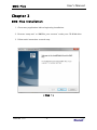
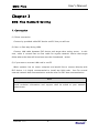
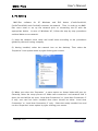
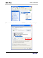
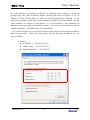
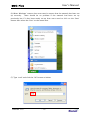
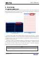
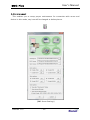
BMS-PLUS BMS Server EKG Viewer Spiro Viewer Version 1.13 BMS-Plus User’s Manual BM S-Plus Professional – Standard Edition Copyright © 2010 Bionet Co., Ltd. All rights reserved. This document is being furnished by Bionet Co., Ltd. For information purpose only to licensed users of the BMS-Plus software product and is furnished on an “AS IS: basis, that is, without any warranties, whatsoever, expressed or implied. Information in this document is subject to change without notice and does not represent a commitment on the part of Bionet Co., Ltd. The software described in this document is furnished under a license agreement. The software may be used only in accordance with the terms of that license agreement. It is against the law to copy or use the software except as specifically allowed in the license. No part of this document may be reproduced or retransmitted in any form or by any means, whether electronically or mechanically, including, but not limited to the way of: photocopying, recording, or information recording and retrieval systems, without the express written permission of Bionet Co., Ltd. BMS-Plus Professional – Standard Edition Initial Publishing March 2010. Printed in Korea. Visit our Web Site at www.ebionet.com Version 1.13 - 1- BMS-Plus User’s Manual Table of Contents Preface Chapter 1 BM S-Plus System Requirem ents Chapter 2 BM S-Plus Installation Chapter 3 BM S-Plus Network Setting Chapter 4 Chapter 5 1. Connection 2. PC Setting 3. Device Setting BM S Server Program 1. Operation guide of EKG Device 2. Start BMS Server Program 3. Menu composition and description EKG Viewer Program 1. Main Screen 2. Menu composition and description 3. Tool bar composition and description 4. Color bar composition and description 5. EKG bar composition and description 6. Setting dialog composition and description 7. Sending Order 8. Run Upgrade 9. File open and close 10. Save as JPEG, PDF file 11. Connection with EKG device 11.1. Monitoring mode 11.2. Recording mode Version 1.13 - 2- BMS-Plus 12. User’s Manual EKG graph viewer control 12.1 Channel 12.2 Rhythm lead 12.3 Sensitivity 12.4 Speed 12.5 Measurement 12.6 Magnifying Glass 12.7 Pacemaker 13. Patient information management 14. Analysis result management 15. Print 15.1 Print Preview 15.2 Print Option 16. Chapter 6 Exit Spiro Viewer Program 1. Main Screen 2. Menu composition and description 3. Tool bar composition and description 4. Color bar composition and description 5. Open and close file 6. Save JPEG, PDF file 7. Manage patient information 8. Manage analyzed information 9. Print 10. Sending order 11. Exit Version 1.13 - 3- BMS-Plus User’s Manual Preface . . . BMS-Plus has been CardioTouch3000, designed Cardio7 and and specially CardioXP programmed completely operable for making in Network environment. If output of print outs have generated by applying various forms, the problems would not occurs. However if various forms of data or when detailed diagnosis are required after measurement process, it was impossible to perform further diagnosis except depending on the output of print out and there was no way to perform further process when the print out has destroyed. In order to overcome these inconveniences and to provide more convenient functionalities, BMS Plus has developed. BMS Plus saves data into hard disk in a digitalized format to resolve problems mentioned from previous paragraph. Furthermore, data can be manipulated and printed out for further diagnosis when and as required by customers. BMS-Plus has remarkable advantages as followings. A. Permanent data acquisition by saving EKG data in computer. B. Measured data can be viewed immediately by using Viewer Program (EKG Viewer, Spiro Viewer). C. For EKG Viewer, all 12 channels can be checked at the same time in monitoring mode, diagnosis can be performed immediately on the PC in recording mode. D. Provide enlargement function by using Zoom function. E. Thickness of data line and background color can be applied in various ways. F. Results of diagnosis can be validated and additional information can be recorded. G. Provide detailed information of the patient and additional information can be recorded. H. Results displayed on the screen can be printed out immediately I. Measured data are converted and saved in a JPEG, PDF, DICOM, TEXT format and saved data can be transferred by using email system J. The created DICOM file can be transferred by interlocking with the PACS program. Enjoy using BMS-Plus software. Version 1.13 - 4- BMS-Plus User’s Manual Chapter 1 BMS-Plus System Requirements Required Items of the PC (BMS-Plus Execution Environment): the recommended environments for the operation of BMS-Plus are nicely summarized in the table below. BMS-Plus users can get the maximum results when running their software under operating systems larger than the recommended. It is highly recommended for the users to run their software under operating systems larger than that recommended by us. Environment Recommended requirement OS Windows98 or higher CPU Pentium III or higher RAM 512MB or more Monitor 17 inch or bigger Graphic Card VGA RAM 64MB or more & Resolution & 1024 x 768 or higher CD-ROM O Network Card Installed(100 M) & static IP required Network environment through hub : Normal LAN cable LAN Cable Direct connection with local PC : Twisted LAN cable EKG Device Software Version Version 1.13 l CardioTouch3000: Version 6.08 or higher l Cardio7 1.10 or higher l CardioXP: Version 1.30 or higher - 5- BMS-Plus User’s Manual Chapter 2 BMS-Plus Installation 1. Close every application before beginning installation. 2. Execute “setup.exe” or “BMSPlus_xxx xxx.exe” under your CD-ROM drive. 3. Follow each instruction on each step. < Step 1 > Version 1.13 - 6- BMS-Plus User’s Manual < Step 2 > < Step 3 > Version 1.13 - 7- BMS-Plus User’s Manual < Step 4 > Note Use the PC by installing both Server and Viewer on a single PC or use the PC by installing the Server and Viewer on separate PCs. The Viewer can be installed on various PCs; however the BMS Server can only be installed on one Server PC. Installing BMS Server on multiple PCs on the same network will make transferring ECGs more difficult. Version 1.13 - 8- BMS-Plus User’s Manual Chapter 3 BMS-Plus Network Setting 1. Connection (1) Direct connection Connect by provided cable EKG device and PC that you will use. (2) Peer-to Peer way (Using HUB) Connect LAN cable between EKG device and target data saving server. In this case, cable is normal Peer-to-Peer cable for regular network. Notice that target folder where the data will be written must be shared(read / write). (3) If you want to use two LAN card in one PC When operator has no server computer and would like to connect directly with EKG device, it is highly recommended to install two LAN cards. One For normal external network data communication and the other for EKG data communication. Note Detail technical information and support shall be asked to your network adminitrator. Version 1.13 - 9- BMS-Plus User’s Manual 2. PC Setting BMS-Plus software for PC Windows and EKG CardioTouch3000 and CardioXP) connects via network. device (CardioCare2000, Thus, in order to run BMS- Plus users need to set up the network prior to connecting the PC with the appropriate device. In case of ‘Windows XP’, follow the step-by-step procedures outlined below to set network. (1) Have the network cards ready and install them according to the procedures guided by the card issuing company. (2) Having installed, select the network icon on the desktop. Then select the ‘Properties’ from option menu by right clicking your mouse. (3) When you select the ‘Properties’, a menu option as shown below will pop up. Generally, when the setup process of ‘Make new connection’ and network card is done, the card will be set up as ‘Local Area Connection’ or ‘Local Area Connection 2’. If only one card has been installed then there should be either ‘Local Area Connection’ or ‘Local Area Connection 2’ only. Select the newly installed icon and run the ‘Properties’ menu option by right-clicking your mouse. Version 1.13 - 10- BMS-Plus User’s Manual (4) To set network, select ‘internet protocol (TCP/IP)’ option and ‘Properties’ option. Version 1.13 - 11- BMS-Plus User’s Manual (5) If the Internet is accessed via network, or computers in hospitals are accessed through the hub, then numerical values should have been pre-input in the ‘IP address (I)’ area, ‘Subnet mask (U)’ and the ‘Default gateway (D)’ as below. In this case you just need to take note of the numbers assigned to IP and gateway; use the same numbers for setting up the device. It is not available to use automatic IP allocation function based on windows system. address manually. You must allocate device’s own IP Also DNS setup is not available. If it is the first time for you to use IP address then please try to connect the device with PC by yourself. Then select the option ‘Use the following IP address (S)’ and input as below. < Example > l IP address -> 192.168.10.186 l Subnet mask –> 255.255.255.0 l Default gateway -> 192,168.10.1 Version 1.13 - 12- BMS-Plus User’s Manual (6) When ‘Windows’ restarts then uses need to ensure that the network has been set up correctly. There should be no problem if the network had been set up previously but if it has been newly set up then users need to click on the ‘Start’ button then select the ‘Run’ on the menu item. (7) Type ‘cmd’ and click the ‘OK’ button as below. Version 1.13 - 13- BMS-Plus User’s Manual (8) If the computers are connected via hub, or the devices are set up through the hub then users can test the connection by inputting the IP address as below. a. Success: Typing the command above a message in the following format generates and repeats itself if it has been correctly set up C:\> Ping 192.168.10.120 Ping 192.168.10.120 with 32 bytes of data: Reply from 102.168.10.120: bytes=32 time<1ms TTL+255. Reply from 102.168.10.120: bytes=32 time<1ms TTL+255. Reply from 102.168.10.120: bytes=32 time<1ms TTL+255. b. Error: If your computer does not perform the command above, it will generate the message in the following format. Under such circumstances you need to check the environment setting of the device, the power supply and the connection of LAN cable; restart the computer. C:\> Ping 192.168.10.120 Ping 192.168.10.120 with 32 bytes of data: Request timed out. Request timed out. Request timed out. Version 1.13 - 14- BMS-Plus 3. User’s Manual Device Setting 3.1 CadioTouch3000/Cardio7 To input the network settings, locate the shadow block on the time display area (Device Setup) and press the rotary key or press with the touch pen to convert the current mode into the ‘Device Setup’ mode. CadioTouch3000 Cardio7 In ‘Device Setup’ mode, select ‘Network Setup’ and press the rotary key. You can setup network information in case of the device is working along with LAN network. In ‘Network Setup’ mode, input the IP Address, Subnet Mask, Gateway and DB Server as below using the rotary key. ‘IP Address’ means the assigned IP address for EKG device and exactly input the same number as your server PC for ‘Subnet Mask’ and ‘Gateway’. DB Server means the computer IP address where all the recorded data send to. Generally, DB server means the PC where the program which can receive data. Note Refer to the equipment manual for detailed network setting instructions. Version 1.13 - 15- BMS-Plus User’s Manual [EKG3000 / Cardio7 Set-up screen] 3.2 CardioXP In the case of the Cardio XP, the ‘System’ menu needs to be selected for the network set-up like in the picture below. Next, select the ‘Network’ menu by using the touch screen or rotary key in the ‘System Setup’ mode. Set up the IP Address, Subnet Mask, Gateway and DB Server by using the touch or rotary key in the ‘Network’ screen like in the picture below. The IP Address is the network address of the CardioXP. Enter the same information as the PC setup in the Subnet Mask and Gateway in order to send the data. The DB server represents the IP address of the PC server, which is used to send the data. In addition, the PC means the computer with BMS-Plus™ program installed. Version 1.13 - 16- BMS-Plus User’s Manual Chapter 4 BMS Server Program BMS Server program enables you to store test data at remote computer by pressing ‘Net’ Key on device. In this case, server will save transferred file after patient name and test date. Version 1.13 - 17- BMS-Plus 1. User’s Manual Operation guide of EKG Device 1.1 Patient inform ation input If you want to transfer test data to desired computer, you need to input patient information in EKG device first. All other information can be edited in computer later on, but only the patient ID must be identified because this will give recognition part of transferred data. About “How to input patient ID”, please see operation manual of CardioTouch3000 and CardioXP. 1.2 Network data transfer In order to transfer data, you can press ‘NET’ key after patient ID input. When you press ‘NET’ key on device, you will be questioned if patient ID is correct or not. Select “Yes” or “No” first. After Yes/No selection, device will ask you “Select EKG”. If you want to send new test data, select “NEW”. data, then select “Recorded”. If you want to send recorded After selection completed, device will process as below sequence. “Recording” à “Analyzing” à “Sending” This is full procedure of data transfer to remote computer. Remote computer could be server or normal personal computer which has network card with it. 1.3 Transfer of saved data For CardioTouch3000, Cardio7 and CardioXP data will be transferred to the server PC if the “Network” key is pressed in the saved data list. Note Transfer method for the saved data list - CardioTouch3000/Cardio7: Selected [List] from the bottom of the main screen. - CardioXP: Select the ‘File’ from the main menu. Version 1.13 - 18- BMS-Plus User’s Manual Note When transmitting multiple sets of data to PC after saving, a network error could occur which may cause transmission halt and subsequent loss of data. Therefore, we recommend users to practice following procedures to minimize such loss. 1. In EKG Main, press [NET] button to transmit data to PC immediately after measuring. 2. When transmitting multiple sets of measurements, rather than sending all data at once, we recommend users to transmit individual data after each measurement. Version 1.13 - 19- BMS-Plus 2. User’s Manual Start BMS Server Program Click start and go to ‘Program’ -> ‘Bionet’ -> ‘BMS Plus’ folder. And execute BMS Server program. Also you can execute BMS Server program by clicking below icon. BMS Server After running the program, BMS Server tray icon will appear on lower right screen. If computer begins receiving data from remote EKG device, tray icon will be changed as below picture. Change d<-> Version 1.13 - 20- BMS-Plus 3. User’s Manual Menu composition and description If you click BMS Server tray icon, you can see below pop up menu. 3.1 Run EKG Viewer This enables you to start ‘EKG Viewer’ program directly. 3.2 Run Spiro Viewer This enables you to start ‘Spiro Viewer’ program directly. 3.3 Data List This menu is used to view list of daily electrocardiogram data saved from device to server PC. When this menu is executed, list screen is displayed as shown below and provide recorded date and time, patient ID, patient name, short description and path of saved file of electrocardiogram. Version 1.13 - 21- BMS-Plus User’s Manual 3.3 Environm ent This enables you to setup proper environment for connection with server and device. In this mode, tray icon will be changed as below picture. [BMS Server Settings] Version 1.13 - 22- BMS-Plus User’s Manual (1) Working Dir: Select working directory where you will save test files. (2) EKG Viewer: It is recommended to make same directory as BMS-Plus ™ working directory. This is the window where you need to link to ‘EKG Viewer’ execution file. If you setup this path, you can start ‘EKG Viewer’ program directly. (3) Spiro Viewer: Menu to set execution path of ‘Spiro Viewer’. side mouse […] button is clicked, a dialog box is prompted. When right hand Find installation folder of BMS-Plus ™ program and set ‘SpiroViewer.exe’ file. (4) File Options: This sets the option related to create and save JPEG, PDF, TEXT or DICOM files. Check the corresponding check box if you want to create and save JPEG, PDF, TEXT or DICOM files. Press the [set...] button to select the necessary setting for each file. (a) JPEG setting This sets the channel type, rhythm channel, gain, filter, image size as necessary for JPEG file creation. Note l If ‘Smoothing Filter’ is set, the EKG graph will be drawn smoothly by the image filter. However, that the filter some cause signal distortion. Version 1.13 - 23- BMS-Plus User’s Manual (b) PDF setting Similar to JPEG file creation, this sets the channel type, rhythm channel, gain, image size as necessary for PDF file creation. (c) TEXT setting This sets the information necessary for the creation of a TEXT file. Version 1.13 - 24- BMS-Plus User’s Manual (d) DICOM setting This sets the image format that will be used to create a DICOM file. Basically, ‘BMP1’ can be selected. u Make DICOM File: This sets the image format for creating DICOM files. Basically, you may choose BMP1; according to PACS systems, however, you can also select BMP2. Note The image colors of DCM files can be changed since each PACS system has different RGB types. In case EKG Grid looks green after the creation of DCM files, you can change the setting to BMP2. Version 1.13 - 25- BMS-Plus n User’s Manual Window Center, Window Width: If the DICOM file looks blurry through the PACS system, it is recommended to use the correct numbers for the program. Contact your PACS provider for the correct numbers. n EKG Modality, Spiro Modality : Contact your PACS provider for the correct Modality. u Send DICOM File: Connect to the PACS system and check the file which you hope to send. Set up the SCP Server by using the [set…] button. n Server: Enter the Server IP or the Server Name. n Port: Please enter the Port number. n AE: Please enter the Application Entity Title. Note [ Send DICOM ] function is only supported on the English version. u Image Format n This configures the necessary settings for creating DICOM files, such as Channel Type, Rhythm Channel, and Gain. (5) Save Options This is the option that is available when the data is saved. (a) Save all at “Working Dir” folder : All files are saved to the folder designated at “Working Dir.” (b) Save at each ID folder : All corresponding files are saved to the folder created by each ID. (c) Save at each file type folder : Files are saved to the folders that are created such as EKG, SPIRO, JPEG, PDF, TEXT, and DICOM. Version 1.13 - 26- BMS-Plus User’s Manual 3.4 Sending Order The inspection order is transferred from PC to CardioXP. Enter the patient information on the ‘Sending Order’ window as shown below; select the item to be examined (Examinations), and then press the [Order] button to transfer the inspection information to the equipment. At this time, make sure that the IP Address of the equipment is entered correctly. Otherwise, an error message will appear, and the transfer will not be made. In addition, ID is essential for EKG when patient information is entered. For Spirometer, ID, Age, Gender, Height, and Race are required. Note l ‘Sending order’ is for CardioXP CarioTouch3000 and Cardio7. Version 1.13 - 27- only. It cannot be used for BMS-Plus User’s Manual 3.5 Run Upgrade It is used to upgrade the CardioTouch3000 and Cardio7 equipment software. It can be used without the need for any upgrade program provided by the manufacturer. For more information on the upgrade of equipment, refer to the manual of the CardioTouch3000 and Cardio7 equipment upgrade software. Note l ‘Run Upgrade’ is for CarioTouch3000 and Cardio7 only. It cannot be used for CardioXP. 3.6 Connection to the equipm ent Send the IP information to the PC, which is connected to the DHCP sever and set up the DB Server information. Note Be sure to connect the ECG machine to the same network as the PC in which the BMS Server is installed. 3.7 Upgrade the software The software can be used to upgrade theCardioTouch3000 and Cardio7 ECG machines. The equipment can be used without the use of additional upgrade programs from the company. Refer to the CardioTouch3000 and/or Cardio7 equipment software upgrade manual for more complete information. Note - CardioXP users are unable to use the upgrade feature in the software. - Please use a cable for the network environment if you upgrade your software. 3.8 Exit This enables you to quit the BMS Server program Version 1.13 - 28- BMS-Plus User’s Manual Chapter 5 EKG Viewer Program 1. Main Screen (1) Menu Bar This is menu bar of ‘EKG Viewer’ Program. There are ‘File’, ‘View’, ‘Tools’ and ‘Help’ menu. (2) (1) (3) (4) (6) (7) (5) (8) (2) Tool Bar This is tool bar of ‘EKG Viewer’ Program. There are ‘File Open’, ‘File Close’, ‘File Save’, ‘1 Screen Display’, ‘2 Screen Display’, ‘Monitoring Mode’, ‘Recording Mode’, ‘Print’ and ‘Help’ Function. (3) Color Bar This is color bar to change the line and color of EKG graph. There are ‘Default Version 1.13 - 29- BMS-Plus User’s Manual Style’, ‘Background Color’, ‘Grid Style’, ‘Inner Grid Style’ and ‘Graph Style’ Function. (4) EKG Bar This is EKG bar to change the EKG graph viewer control. There are ‘Channel’, ‘Rhythm Ch’, ‘Gain’, ‘Speed’, ‘Measure’, ‘Glass’, and ‘Pacemaker’ Function. (5) Status Bar This is status bar to display each state. (6) Information & Analysis Window This is to display input information from EKG device and the result of analysis. (7) EKG Graphic Data Display Window This is to display the EKG graph. If you see the graph in the full screen mode, double click the left button of mouse. And press the ‘ESC’ key to return of original screen mode. The below tab is to display opened file name. Chang e <-> (8) EKG Beat Parameter Display Window This is to display the bit parameter of EKG data. If you hide this window, press the ‘Minimize’ button. Version 1.13 And if you display this window again, press the ‘Restore’ button. - 30- BMS-Plus 2. User’s Manual Menu composition and description This is menu bar of ‘EKG Viewer’ Program. There are ‘File’, ‘View’, ‘Tools’ and ‘Help’ menu. 3. Tool bar composition and description This is tool bar of ‘EKG Viewer’ Program. There are ‘File Open’, ‘File Close’, ‘File Save’, ‘1 Screen Display’, ‘2 Screen Display’, ‘Monitoring Mode’, ‘Recording Mode’, ‘Print’ and ‘Help’ Function. (1) (2) (3) (4) (5) (6) (7) (8) (9) (1) File Open: Select the EKG file and open it. (2) File Close: Close the file which is open. (3) File Save: Change this open file to JPEG, PDF, DCM file and save. (4) 1 Screen Display: Change the EKG display screen into one screen. (5) 2 Screen Display: Change the EKG display screen into two screens. This is useful when the two inspections are compared. Version 1.13 - 31- BMS-Plus User’s Manual (6) Monitoring Mode: This monitors the EKG signal of the connected terminal and it is possible when there is no processing inspection also you can set the information of the connected terminal at fundamental setup. (7) Recording Mode: This records the EKG signal and saves as the file and this file is saved under the [Recording] folder by creating the file name(present time), it is possible when there is no processing inspection also you can set the information of the connected terminal at fundamental setup. (8) Print: This prints EKG graph or other inspection information. (9) Help: It displays program information. Version 1.13 - 32- BMS-Plus 4. User’s Manual Color bar composition and description You can choose grid or graph color which is most convenient for you and select line thickness how it appears on monitor using this bar. (1) (2) (3) (4) (5) (1) Default Style: You can change all into default style. (2) Background Color: You can setup back ground color of chart paper on monitor. (3) Main Grid Style: You can choose color or line thickness for main grid. (4) Inner Grid Style: You can choose color or line thickness for inner grid. (5) Graph Style: You can choose color or line thickness for EKG graph 5. EKG bar composition and description This is EKG bar to change the EKG graph viewer control. (1) (2) (3) (4) (5) (6) (7) (1) Channel: This is the function to set up the channel form. Four types of channel forms are provided: 3ch+1rhy, 6ch+1rhy, 12ch rhy and beat report. (2) Rhythm CH.: This is the function to select the rhythm lead. This rhythm lead in 3CH, 6CH, the Rhythm Lead is recorded for 10 seconds on the bottom of the printing form; it becomes the standard for other channels. (3) Gain: This is the function used to adjust the sensitivity. There are four ways of setting up auto (automatic sensitivity adjustment) function and setting up all the 12 channels to 5 mm/mV, 10 mm/mV, 20 mm/mV. (4) Speed: This is the function used to adjust the signal width. Three values, 12.5 mm/s, 25 mm/s, and 50 mm/s are available for adjustment. (5) Measure: This is the function used to measure the width or height of EKG graph data. Version 1.13 - 33- BMS-Plus User’s Manual (6) Glass: This is the function used to magnify the part of EKG graph data. (7) Pacemaker: It is the function to determine whether Pacemaker’s mark will be marked. Note The Measure and Glass functions work in the recording mode. They do not work in the monitoring mode. 6. Setting dialog composition and description (1) Connected Terminal Information The connected terminal information is only used in case of monitoring and recording. Also, the connected terminal information can be used by selecting an automatic IP or fixed IP. - Automatic IP: The IP address of the connected terminal can be selected in the combo box - Fixed IP: Directly enter and set-up the IP address of the connected terminal Version 1.13 - 34- BMS-Plus User’s Manual Note If you register the equipment after setting up the automatic IP, the registered equipment connects itself automatically from the second implementation of opening the program. If the registered network is not connected with the network, the IP is indicated as 0.0.0.0 such as “0.0.0.0: ********”. Please confirm the network condition of the equipment. Note It is recommended to use wired Ethernet for the network environment. (2) Display Resolution: This adjusts the size of the EKG graph screen. The size of the basic signal is set at display mode and generally one stage lower resolution than monitor resolution is recommended and the size of the full screen is same as the size of the full screen mode. Generally the same provision as the monitor resolution is recommended. (3) JPEG Image: This adjusts the size of the JPEG image. (4) DICOM File Conversion This sets the image format for creating DICOM files. Basically, you may choose BMP1; according to PACS systems, however, you can also select BMP2. Note The image colors of DCM files can be changed since each PACS system has different RGB types. In case EKG Grid looks green after the creation of DCM files, you can change the setting to BMP2. (5) Save Directory: This sets the route for saving the EKG file if recording is to be made on the PC (EKG Viewer) (6) Doctor/Hospital Information You can input and correct doctor/hospital information. The set data will be entered into their respective files in case of Remote Recording. Version 1.13 - 35- BMS-Plus User’s Manual 7. Sending Order The inspection order is transferred from PC to CardioXP. Enter the patient information on the “Sending Order” window as shown below and press the [Order] button to transfer the inspection information to the equipment. At this time, make sure that the IP Address of the equipment is entered correctly in the setting menu. Otherwise, an error message will appear, and the transfer will not be made. In addition, ID is essential when patient information is entered. Note l ‘Sending order’ is for CardioXP only. It cannot be used for CarioTouch3000 and Cardio7. 8. Run Upgrade It is used to upgrade the CardioTouch3000 and Cardio7 equipment software. It can be used without the need for any upgrade program provided by the manufacturer. For more information on the upgrade of equipment, refer to the manual of the CardioTouch3000 and Cardio7 equipment upgrade software. Note l CardioXP users are unable to use the upgrade feature of the program. l Please use wired Ethernet for the network environment if you upgrade your software. Version 1.13 - 36- BMS-Plus 9. User’s Manual File open and close This is the function used to open stored file. Below window is normal file searcher. 10. Save as JPEG, PDF, DCM files Save the open file after changing into the JPEG or PDF or DCM file. Note The file can only be saved if the wave pattern is acquired through the Record mode. (EKG, JPG, PDF, DCM) 11. Connection with EKG device If device is turned on and connected by proper cable, then clicking connection button will introduce you welcome message. If it doesn’t work, check the IP address of connected device. Then check LAN cable. Please note that the LAN cable must be twisted one in case of direct connection not a network environment through hub. Version 1.13 - 37- BMS-Plus User’s Manual 11.1 M onitoring m ode When you want to monitor EKG signals, you can click ‘Monitoring mode’ icon from above toolbar. Monitoring mode can be used to check if the signal is stable or not. If operator thinks the signal is fine, then start to record or analysis afterwards. In monitoring mode, it is fixed the 12 channel viewer mode, only sensitivity control is possible. 11.2 Recording m ode To use recording mode, click ‘Recording mode’ icon from above toolbar. After click this icon, data acquisition status will be displayed first and processing status will be displayed on process bar. Version 1.13 - 38- BMS-Plus User’s Manual Same as recording mode, you can see data acquisition status and processing status information as bar information. It will take about 30 seconds to get a result. If it doesn’t work, you can see the error message. Then check connection with EKG device. 12. EKG graph viewer control 12.1 Channel After acquition the data or data with analysis result, 3 channel or 6 channel viewer option could be used to study more detailed waves. This function is only avaiable when you open stored data or just acquired data from patient by recording or analysis mode. By using stored file, recorded date or analysis data, you can see 12 channel view by clicking ‘12Ch’. In 12 channel viewer mode, rhythm lead has no meaning. It is possible to select sensitivity and speed of data. (1) 12 CH: 12 Channels Version 1.13 - 39- BMS-Plus User’s Manual (2) 6 CH + 1: 6 Channels + 1 Rhythm Channel (3) 3 CH + 1: 3 Channels + 1 Rhythm Channel Version 1.13 - 40- BMS-Plus User’s Manual (4) Beat Report: Bit Parameter (Pon / Poff / QRSon / QRSoff / Toff) This is to display the bit parameter of EKG data. If you hide this window, press the ‘Minimize’ button. And if you display this window again, press the ‘Restore’ button. 12.2 Rhythm lead Choose any rhythm that you want to setup as representative rhythm lead. This is the function to select the rhythm lead. This rhythm lead in 3CH, 6CH, the Rhythm Lead is recorded for 10 seconds on the bottom of the printing form; it becomes the standard for other channels. Version 1.13 - 41- BMS-Plus User’s Manual 12.3 Sensitivity This is the function used to adjust the sensitivity when the sensitivity is so high that the signal is overlapped with the signals of the adjacent channels, or when the sensitivity is so low that the reading is difficult. There are four ways of setting up auto (automatic sensitivity adjustment) function and setting up all the 12 channels to 5 mm/mV, 10 mm/mV, 20 mm/mV. 12.4 Speed This is the function used to adjust the signal width. Three values, 12.5 mm/s, 25 mm/s, and 50 mm/s are available for adjustment. 25 mm/s means to record the signal of the electrocardiogram for a second on 25 mm. Therefore, the width of 12.5 mm/s is a half of the width of 25 mm/s, and the width of 50 mm/s becomes two times of the width of 25 mm/s. If you want to record the broad width of the signal, set up the higher value. 12.5 M easurem ent This is the function used to measure the width of EKG graph data. And this is the function used to measure the height of EKG graph data. Version 1.13 - 42- BMS-Plus User’s Manual 12.6 M agnifying Glass This is the function used to magnify the part of EKG graph data. Version 1.13 - 43- BMS-Plus User’s Manual 12.7 Pacemaker Place the pacing mark if the pacemaker signal is detected. 13. Patient information management If you want to view the patient information select the ‘Information’ tab. And select the ‘Analysis’ tab to view the analysis result. If you want to edit the data, press the ‘Edit’ button, and press the ‘Save’ button to save edited data. If you hide this window, press the ‘Minimize’ button. And if you display this window again, press the ‘Restore’ button. - Patient Information - Hospital & Doctor Information - Recorded Date & Time Information 14. Analysis result management If you want to check and edit analysis result or add more description on it, then please click ‘Analysis’ tab button. If you want to edit the data, press the ‘Edit’ button, and press the ‘Save’ button to save edited data. (1) Analysis Parameter - Heart Rate - PR Interval - QRS Duration - QT/QTc - P/R/T Axis (2) Analysis Result (3) Doctor Comment Version 1.13 - 44- BMS-Plus 15. User’s Manual Print 15.1 Print Preview You can use this function, when you want to preview printed EKG data. 15.2 Print Option If you want to print recorded EKG data or stored EKG data, click print icon from above toolbar. You can use this function to set the printer or change print option. printing, make sure your paper setup as “Landscape” format. Version 1.13 - 45- Before the BMS-Plus User’s Manual Note 16. - The speed of printing is fixed to 25mm/sec. - The wave patterns of the monitor cannot be printed. . Exit You can use whenever you want to exit from the BMS-Plus. However all users strongly recommended to be very careful not to loose your data. Version 1.13 - 46- BMS-Plus User’s Manual Chapter 6 Spiro Viewer Program 1. Main screen (1) (2) (3) (5) ) ) (6) ) (7) (8) ) ) (4) ) (1) Menu bar Provide program menu of ‘Spiro Viewer’. and ‘Help’ components. Version 1.13 Menu bar is composed of ‘File’, ’View’ ) - 47- BMS-Plus User’s Manual (2) Tool bar Indicate program tool bar of ‘Spiro Viewer’. Tool bar is composed of ‘Open file’, ‘Close file’, ‘Save JPEG’, ‘1 View screen’, ‘2 View screen and ‘Help’ component. (3) Color bar This menu is used when change line of graph and color are required. Basic options of ‘Default Style’, ‘Grid Style’, ‘BASE Style’, ‘POST Style’ and ‘Reference Style’ are provided. (4) Status bar Provide descriptions of current status. (5) Patient information and diagnosis window This menu is used when view or modify opened information of patient. (6) Graph display window Provide graph of Spiro data. Shape of graph changes depending on the diagnosis types. (7) Diagnosis/description display window This menu is used when view or modify diagnosis information and descriptions recorded by doctors. (8) Parameter display window Display parameter value of opened data. Version 1.13 - 48- BMS-Plus 2. User’s Manual Menu configuration and descriptions Picture below shows menu bar of ‘Spiro Viewer’ program. largely of ‘File’, ‘View’ and ‘Help’ components. Version 1.13 - 49- Menu bar is composed BMS-Plus 3. User’s Manual Tool bar configuration and descriptions Picture below shows tool bar of ‘Spiro Viewer’ program. (1) (2) (3) (4) (5) (6) (7) (1) File Open: Used when open new file. (2) File Close: Used when close file. (3) File Save: Used when save opened file into JPEG, PDF, DCM image. (4) 1 Screen Display: Display graph in one window. (5) 2 Screen Display: Display graphs in 2 windows. compare 2 graphs. (6) Print: Used when print out electrocardiogram data. (7) Help: Display program information as shown below. Version 1.13 - 50- This function is useful when BMS-Plus 4. User’s Manual Color bar configuration and descriptions This menu is used when change electrocardiogram graph displayed on the screen as required by user. (1) (2) (3) (4) (5) (6) (7) (1) Default Style: Used when apply basic configuration recommended by manufacturer. (2) Grid Style: Used when change grid color of graph, thickness and shape displayed on the screen. (3) Graph Style: Used when change graph color of graph, thickness and shape displayed on the screen. (4) Reference Style: Used when change reference color, thickness and shape of FV (Flow-Volume) graph for FVC data. (5) Zoom: Used when enlarge or reduce graph size. (6) Graph Type: Used when convert type of FV (Flow-Volume)/VT (Volume-Time) graph for FVC data. (7) Graph Display: ‘FVC Graph” is used to set the 'FVC' graph format. If it will be set up as 'All', the all graphs of three times test are printed. And if it will be set up as 'BEST", the best one graph of three times test are printed. Note In case of doing an 'FVC POST' test, even if ‘FVC Graph” is set up as 'All', the best one graph of three times test are printed. Version 1.13 - 51- BMS-Plus 5. User’s Manual Open and close file This menu is used when open saved file or to close opened file. 6. Save JPEG, PDF, DCM files Convert currently opened file and saved to JPEG or PDF or DCM image. [When create information file when JPEG and PDF file is saved] is selected, text type information file is created when data is saved into JPEG or PDF image. Version 1.13 - 52- BMS-Plus 7. User’s Manual Manage patient information This window is used when view or modify currently opened patient information. If you wish to modify patient information, click on ‘Edit Info’ and modify desired information. In order to save modified information, click on the ‘Save information’ button for automatic saving function. - Patient information - Information of hospital and doctor in charge - Information of recorded date and time 8. Manage analyzed information This window is used to view, input or modify currently opened diagnosis information entered by doctor in charge. If you wish to modify diagnosis information entered, enter new information in ‘Comment’ field then click on ‘Save comment’ button. Contents provided on right hand side displays parameter values of currently opened data. The window can be hidden by using ‘Minimize’ button located on the top right hand side of window and restored when ‘Restore’ button is clicked. Version 1.13 - 53- BMS-Plus 9. User’s Manual Print 9.1 Print preview Provide preview of file to be printed. Version 1.13 - 54- BMS-Plus User’s Manual 9.2 Print option This menu is used when print out currently opened graph. Configure or change settings of printer, number of pages to print and print options are applied. 10. Sending order It transfers the inspection order from the PC (Spiro Viewer) to Cardio XP. Enter the patient information, select the item of examination (Examinations), and then press the [Order] button. ID, Age, Gender, Height, and Race are essential when patient information is entered. Note l ‘Sending order’ is for CardioXP only. It cannot be CarioTouch3000 and Cardio7. 11. Exit This menu is used to end current session of Spiro-Plus ™ program. Version 1.13 - 55- used for