1
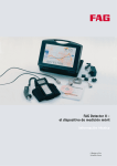
FAG Detector II –
the “mobile” among data collectors
Technical Product Information
Application · Condition-based maintenance · Principle
Application
The FAG Detector II is a vibration
measuring device and data collector
rolled into one. Together with the
PC software Trendline, the device
was developed for data collection
in offline plant monitoring. The
FAG Detector II is easy and
comfortable to use. It has a low
mass. It is thus suitable for the
monitoring of large plants where
a measurement round would involve
covering a considerable distance.
With this device, parameters for
vibration acceleration and vibration
velocity can be measured in freely
definable frequency bands.
Machine vibrations are monitored
according to ISO 10816 and the
rolling bearing condition can be
assessed by means of the
demodulation detection method.
Raw and demodulated signals can
be stored and thus more detailed
analysis of the vibration signals
can be carried out in relation to
time and frequency ranges. Imbalance
and misalignment can be detected
precisely, as can rolling bearing
damage and gear problems.
In addition, the device is equipped
with a temperature measurement
probe.
which is absolutely essential for
this type of maintenance, can be
recovered in a very short space of
time. This is particularly true if the
reasonably priced, easy to use and
handy FAG Detector II is chosen.
The device is also suitable for
personnel that have no knowledge
of vibration measurement. Use of
the device is straight forward and
can be learnt quickly. The user can
generate individual routes and is
then guided systematically from
one measurement point to the next.
The acceleration sensor is attached
to the machine by means of a
magnetic foot. At any time, the
user can depart from a previously
defined “measurement round” and
add further measurement points.
Data are measured and stored by
simply pressing a key.
The principle
The FAG Detector II measures
vibration signals at predefined
measurement points using a sensor
and uses these to calculate the
RMS values for vibration velocity,
vibration acceleration and
demodulated acceleration. These
values for characterising the
machine or component condition
are described in further detail in
the table on page 6. Frequency
bands of any width between 2 Hz
and 20 kHz can be defined and
monitored. The FAG Detector II has
a dynamic memory management
system and the base version can
store up to 24 time signals. With
expanded memory, up to 116 time
signals can be stored using the
“FIS.DETECTORII.SET.1MB”.
Condition-based
maintenance
Condition-based maintenance
means: identifying damage at an
early stage, defining planned
repairs, making optimum use of
bearing life, and achieving
considerable reduction in costs,
in particular those relating to
production stoppages. The costs
of purchasing a diagnostic device,
3
Principle · Operation
With an infrared sensor, this device
can also be used for non-contact
temperature measurement. After a
measurement round, the parameters
measured are transferred to a
computer for evaluation, analysis
and diagrammatic presentation
using the software Trendline.
The precise location of the
measurement points within the
plant to be monitored is filled in the
configuration. This also contains
the sensor sensitivity and limit
values for the main alarm and
pre-alarm for each measurement
point.
The configuration is generated
using the software FAG Trendline
and transferred to the Detector
prior to measurement.
The sensor must be securely
attached as close as possible to
the point to be measured. In general,
it is attached by means of the
screw-mounted magnetic foot.
4
If this is not possible, for example
with an aluminium housing, a small
iron plate or support washer with
the same size as the magnetic foot
is attached to the measurement
point. This can be carried out using
hard-curing instant adhesives
(e.g. cyanoacrylate adhesives).
On the FAG Detector II, this
measurement location is selected
in the configuration and measurement
is started. During measurement,
the speed should be constant
(at least 120 or 600 min –1 are
required for Vsel or ISO 10816
respectively).
The device records the sensor
signals according to the selected
bandwidths and calculates the
characteristic values.
For each configuration, the
FAG Detector II compares the new
measured characteristic values with
the defined limit values for main
alarm and pre-alarm for this
measurement location. If
one of these threshold
values is exceeded, this is
displayed immediately on
the device. After a
measurement session,
the stored values are
transferred to the computer.
With the aid of trend analysis, the
user can estimate when an alarm
will probably be triggered.
When an alarm is triggered, an
alarm report can be generated and
printed out. In order to ensure
comparability of values, they
should be recorded under identical
conditions. After an initial reference
measurement, measurements are
carried out at regular intervals.
E-mail button on the FAG Detector II
One very useful feature of the
software, particularly for users with
little experience of vibration
measurement, is the e-mail button.
This can be used to send
measurement data to a vibration
expert by e-mail at the touch of a
button. In this way, an external
diagnosis expert can be consulted
for sophisticated analyses. Our F’IS
service department will always be
pleased to help you with such
analyses.
User friendly
The display on the FAG Detector II
shows the user all the information
needed to operate the device:
• selection of the measurement
point,
• user guidance during measurement,
• display of measurement results,
• the system settings.
The device can be easily operated
using just the six keys on the soft
keyboard.
Features · Ordering designation and scope of delivery
Features
• If you wish: you collect the data,
we carry out a remote diagnosis
• Portable, handy, easy to use
diagnostic device
• Low mass – 450 g
• Operation with one hand using
6 keys
• Dust and spray-resistant
soft keyboard
• Working temperature 0 to 50 °C
• Automatic switch off after
approx. 2 minutes
• Monitoring functions:
– general vibration condition
– rolling bearing condition
– data collector for up to
1200 measurement points
– headset jack for
acoustic noise assessment
• Storage and display of up to
4 measurement values per
measurement point for straightforward condition assessment
• Simple PC trend/graphics
software with database for
WIN 98/NT/2000/XP
• Sensor cable length possible
up to 50 m
Ordering designation and
scope of delivery
Ordering designation:
FIS.DETECTORII.SET
or
FIS.DETECTORII.SET.1MB
Accessories
• Second attachable bag
for holding acceleration sensor
• Sensor extension cables
for lengths of 5 m and 15 m are
available on request
FAG DETECTOR II
Scope of delivery:
• Basic device with storage battery
• Acceleration pickup
with magnetic foot
• Temperature sensor
• Power pack
• PC data cable
• User manual
• Protective bag with holder
for temperature sensor
• PC software Trendline
• Case
• USB serial adapter
5
Selection of characteristic values
Selection of characteristic values
Possible characteristic values and signals
for each measurement point
Measurement range/Resolution
Frequency range
Display
Characteristic value: vibration severity to ISO 10816
(VDI 2056) (broadband RMS value of vibration velocity)
for general assessment of machine condition
according to ISO 10816
ISO 10816 = 0 – 999,9 mm/s
10 Hz – 1 kHz
Detector
and PC
Characteristic value: vibration severity (freely selectable)
(RMS value of vibration velocity,
e.g. for detection of imbalances and misalignment)
Vsel = 0 – 999,9 mm/s
Freely selectable
between
2 Hz and 1 kHz
Detector
and PC
Characteristic value: acceleration
(broadband RMS value of vibration acceleration,
e.g. for monitoring of gearboxes)
Aeff = 0 – 25 g
2 kHz – 20 kHz
Detector
and PC
Characteristic value: acceleration (freely selectable)
(e.g. for selection gear set monitoring)
Asel = 0 – 25 g
Freely selectable
between
15 Hz and 20 kHz
Detector
and PC
Characteristic value: demodulated signal 100 Hz/1000 Hz
(RMS value of demodulated signal up to 100/ 1000 Hz,
e.g. for monitoring of rolling bearing condition)
Deff/TP100/1000 Hz = 0 – 25 g
0 Hz – 100 Hz/
0 Hz – 1000 Hz
Detector
and PC
Characteristic value: demodulated signal 100 Hz/1000 Hz
(freely selectable)
(e.g. for selective monitoring of rolling bearing condition)
Dsel/TP100/1000Hz = 0 – 25 g
Freely selectable
0 Hz – 100 Hz/
0 Hz – 1000 Hz
Detector
and PC
Time signal of vibration acceleration
up to 1 kHz, 4096 values
±25 g
2 Hz at 1 kHz
PC
Time signal of vibration acceleration
up to 20 kHz, 4096 values
±25 g
2 Hz at 20 kHz
PC
Demodulated time signal
up to 100 Hz,
up to 1 kHz
±25 g
0 Hz to 100 Hz
0 Hz to 1 kHz
PC
Frequency spectrum (Fourier transform)
of time signal of vibration velocity up to 1 kHz
±999,9 mm/s
Resolution: 0,73 Hz
2 Hz to 1 kHz
PC
Frequency spectrum (Fourier transform)
of time signal of vibration acceleration
up to 20 kHz
±25 g,
Resolution: 14,6 Hz
15 Hz to 20 kHz
PC
Frequency spectrum (Fourier transform)
of time signal of demodulated signal or
up to 100 Hz or up to 1 kHz
±25 g,
0 Hz to 100 Hz
Resolution: 0,073 Hz (at 100 Hz), or
0,73 Hz (at 1 Hz)
0 Hz to 1 kHz
PC
Measurement point temperature
Temp = –15 °C to 240 °C
Detector and PC
–
On the PC, the user can specify for each measurement point whether and under what conditions certain time signals are to be stored.
Three different time signals can be measured, namely vibration acceleration (2 Hz – 1 kHz, 3 kHz scan rate),
vibration acceleration (2 Hz – 20 kHz, 60 kHz scan rate) and demodulated signal (0 Hz – 100 Hz/1 kHz , 300 Hz/3 kHz scan rate).
The Detector can, depending on the memory size, store 24 or 116 time signals.
6
Technical data
Device designation
FAG Detector II, ordering designation FIS.DETECTORII.SET
with expanded memory FIS.DETECTORII.SET.1MB
Dynamic memory
max. 1200 measurement points without time signals,
Basic version: 256 kbyte, up to max. 24 time signals can be stored,
with expanded memory: 1 Mbyte, up to max. 116 time signals can be stored
PC interface
RS 232, baud rate: 38,2 kbps 57,6 kbps
Display
Illuminated graphic display (LCD), 128 ~ 64 pixels
Dimensions: 55 ~ 33 mm
Inputs
BNC jack for ICP acceleration sensor with adjustable
sensitivity: (mV/g),
9 pin jack for pyrometer (IR temperature sensor),
9 pin DIP jack with RS232 interface for PC data cable supplied,
Connector for battery charger
Output
Connector for headset with 3,5 mm jack plug (Walkman), signal: demodulated signal
Detector languages
switchable between German, English, French, Dutch, Italian, Turkish,
Spanish, Portuguese, Swedish and Finnish,
other languages available by agreement
Keyboard
6 soft keys
Manual
German, English and French
Power supply
Rechargeable NiMH batteries
Operating time
Approx. 6 – 8 hours (continuous operation)
Temperature range
0 ... +50 °C (working temperature)
–20 ... +70 °C (transport and storage temperature)
Dimensions (basic device)
230 ~ 70 (53) ~ 45 (53) mm (L ~ B ~ H)
Mass (basic device)
ca. 450 g
Protective bag
Two compartments, black nylon, 2 transparent film windows,
openings with velcro fasteners, velcro holders for cable and sensor, carry strap
PC software Trendline
Runs under WINDOWS 98/NT 4.0 SP6/2000/XP
• Configuration of FAG Detector II via RS232 interface
• Hierarchy-based factory and measurement point manager with machine graphics facility
• Generation of any number of measurement routes on PC
• Integral database for storage of measurement values
• Graphic representation of measurement values and their behaviour, trend analysis
and trend extrapolation
• Presentation of recorded time signals
• FFT presentation of time signals
• Report generator for alarms and measurement values
• Available in German, English, French and Portuguese (others in preparation)
Temperature measurement
IR temperature sensor, handheld device for non-contact temperature measurement,
measurement range –15 ... +240 °C (1 mV/°C/°F), spectral range 8 – 14 µm,
minimum target 2,5 mm, distance ratio 4 : 1,
connector plug for DETECTOR II
7
98/09/05 Printed in Germany by Weppert Print & Media GmbH
FAG Kugelfischer AG & Co. oHG
P.O. Box 1260
D-97419 Schweinfurt
Every care has been taken to ensure the
correctness of the information contained
in this publication but no liability can be
accepted for any errors or omissions.
Georg-Schäfer-Strasse 30
D-97421 Schweinfurt
We reserve the right to make changes in
the interest of technical progress.
Service-Hotline
© by FAG · 2005, September
Phone +49 2407 9149-99
This publication or parts thereof may not
Fax
be reproduced without our permission.
+49 2407 9149-59
www.fis-services.com
TPI WL 80-62/2 E