1
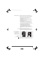
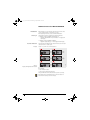
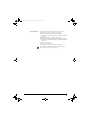
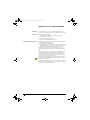
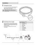
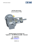
ba12__en_gb__de.book Seite 1 Donnerstag, 13. September 2012 10:47 10
FAG Motion Guard C6-MP-DISTRIBUTOR
Distributor
User manual
ba12__en_gb__de.book Seite 1 Donnerstag, 13. September 2012 10:47 10
FAG Motion Guard C6-MP-DISTRIBUTOR
Distributor
User manual
ba12__en_gb__de.book Seite 2 Donnerstag, 13. September 2012 10:47 10
Safety guidelines and symbols
High product safety
Follow instructions
Definition of guidelines and
symbols
Warning
Caution
Note!
�
Original user manual
2
BA 12
Our products correspond to the current level of research and
technology. If the bearing arrangement is designed correctly,
the products are handled and fitted correctly and as agreed and
if they are maintained as instructed, they do not give rise to any
direct hazards.
This publication describes standard products.
Since these are used in numerous applications, we cannot make
a judgement as to whether any malfunctions will cause harm to
persons or property.
It is always and fundamentally the responsibility of the designer and
user to ensure that all specifications are observed and that all
necessary safety information is communicated to the end user.
This applies in particular to applications in which product failure
and malfunction may constitute a hazard to human beings.
The warning and hazard symbols are defined along the lines of
ANSI Z535.6–2006.
The meaning of the guidelines and symbols is as follows:
If these safety guidelines are not observed, death or serious injury
may occur.
If these safety guidelines are not observed, minor or slight injury
will occur.
If these safety guidelines are not observed, damage or malfunctions
in the product or the adjacent construction will occur.
There follows additional or more detailed information that must be
observed.
Numbers within a circle are item numbers.
This user manual is the original user manual in accordance with the
Machinery Directive 2006/42/EC.
Schaeffler Technologies
ba12__en_gb__de.book Seite 3 Donnerstag, 13. September 2012 10:47 10
FAG Motion Guard C6-MP-DISTRIBUTOR
Page
Features
Scope of delivery ...................................................................... 4
Ambient conditions................................................................... 5
Legal guidelines........................................................................ 5
Design and safety guidelines
Intended purpose ..................................................................... 6
Responsible persons ................................................................ 6
Qualified personnel .................................................................. 6
Protective equipment................................................................ 6
Lubrication system.................................................................... 6
Mounting
Mounting of connectors ............................................................ 7
Joint mounting .......................................................................... 8
Separate mounting ................................................................... 9
Initial operation
Determining the lubricant quantity ........................................... 10
Setting the service life .............................................................. 10
Configuring outlets ................................................................... 10
Initialisation.............................................................................. 12
Operation
Inspection................................................................................. 14
Additional lubricant quantity .................................................... 14
Switching off ............................................................................. 15
Malfunction
Eliminating the malfunction...................................................... 16
Error messages ......................................................................... 17
Technical data
Distributor................................................................................. 18
Replacement parts .................................................................... 19
Accessories............................................................................... 20
Service ...................................................................................... 20
EU Declaration of Conformity
................................................................................................. 21
Quick guide manual
Configuring outlets ................................................................... 22
Preparing the distributor........................................................... 23
Mounting the lubrication system .............................................. 23
Determining the service life ...................................................... 23
Switching on the lubrication system ......................................... 23
Switching off the lubrication system ......................................... 23
Schaeffler Technologies
BA 12
3
ba12__en_gb__de.book Seite 4 Donnerstag, 13. September 2012 10:47 10
FAG Motion Guard C6-MP-DISTRIBUTOR
Features
The FAG Motion Guard C6-MP-DISTRIBUTOR provides lubricant
to the lubrication points. The maximum pressure is 25 bar.
The lubricant is supplied from an FAG lubricator.
The service life and lubricant quantity are set on the lubricator.
The lubricant cartridge in the lubricator is designated as
an LC unit. The unit comprising the lubricator and the distributor
is the lubrication system.
The user manual must always be complete and in a legible condition.
Users of the distributor must have this user manual available and
must observe the information in the manual.
� Distributor
� Box of accessories
� Connectors, straight type G1/8,
6 pieces
� Connectors, elbow type G1/8,
6 pieces
� Closing plugs G1/8,
4 pieces
� User manual
� Connection cable, short type,
C6-KIT only
� Drilling template, C6-KIT only
Holder, C6-KIT only
�� Lubricator, C6-KIT only
The items included in delivery are shown in Figure 1.
8
10
9
7
6
2
Figure 1
Scope of delivery
Note!
4
BA 12
1
4
3
5
00016346
Scope of delivery
Check the delivery and report any damage in transit as a complaint
to the deliverer. Any missing items or other defects must be reported
as a complaint to Schaeffler Technologies AG & Co. KG.
Schaeffler Technologies AG & Co. KG accepts no liability for
any defects that are the subject of retrospective complaints.
Schaeffler Technologies
ba12__en_gb__de.book Seite 5 Donnerstag, 13. September 2012 10:47 10
Ambient conditions
If the distributor is screwed together correctly with the lubricator,
it is resistant to dust and spray water. However, the sealing rings
and plastics may be attacked by ambient media. Uniform dispensing
of lubricant and pressure build-up to a maximum of 25 bar can
only be ensured at operating temperature.
Protect the distributor against chemically aggressive environments.
Operating temperature
Storage
Legal guidelines
The distributor can be used in the temperature range from –20 °C to
+60 °C.
Store the distributor in a dry, dust-free environment in
the temperature range from +15 °C to +25 °C.
The information in this manual corresponded to the most recent
status at the close of editing. The illustrations and descriptions
cannot be used as grounds for any claims relating to lubricators
that have already been delivered.
Schaeffler Technologies AG & Co. KG accepts no liability for any
damage or malfunctions if the lubrication system has been modified
or used in an inappropriate manner.
Schaeffler Technologies
BA 12
5
ba12__en_gb__de.book Seite 6 Donnerstag, 13. September 2012 10:47 10
FAG Motion Guard C6-MP-DISTRIBUTOR
Design and safety guidelines
Intended purpose
Responsible persons
Qualified personnel
Protective equipment
Lubrication system
6
BA 12
The distributor provides the same quantity of grease to up to
six lubrication points. Typical areas of application include
the lubrication points on rolling and plain bearings, drive and
conveyor chains, guidance systems, open gearboxes and seals.
The operator and safety co-ordinator are defined as responsible
persons. The operator is the natural or juristic person that uses
the distributor or on whose instruction the distributor is used.
The distributor and lubrication system may only be operated by
qualified personnel.
A person defined as qualified personnel:
■ is authorised to use the distributor by the safety co-ordinator
■ has all the necessary knowledge
■ is familiar with the safety guidelines
■ has read and understood this manual.
Protective equipment is intended to protect personnel against
health hazards.
When working with the distributor, the following protective
equipment must be used at all times:
■ protective goggles.
If the lubrication system fails, take appropriate measures to prevent
possibly material damage.
Caution
Do not modify the distributor. Keep grease away from eyes,
skin and clothing. Observe the safety data sheets for the greases.
Warning
While working on machinery and plant, the safety guidelines and
user manuals of the manufacturers must be observed.
Schaeffler Technologies
ba12__en_gb__de.book Seite 7 Donnerstag, 13. September 2012 10:47 10
Mounting
Collect the material required for mounting. Order accessories as
appropriate, see table Accessories, page 20.
The material required is as follows:
■ connectors
■ lubricant feed line
■ connection cable, short type,
(connection cable, 2 m for separate mounting)
■ holder (included in the KIT)
■ grease cartridge (400 g) for prelubrication
■ lubricator (included in the KIT)
■ connector G1/8 for lubricator and connector G3/8 for distributor
(only for separate mounting).
The distributor should be fitted exclusively with connector and
lubricant feed lines supplied by
Schaeffler Technologies AG & Co. KG.
Fitting of connectors
Before joint or separate mounting, fit the connectors, Figure 2:
■ Define the outlets to be used.
■ Screw connectors into the outlets to be used,
observing the maximum torque of 2 Nm.
■ Screw the closing plugs into the outlets not required.
3
1
Figure 2
Lubricator
FAG Motion Guard CONCEPT6
C6-MP-DISTRIBUTOR
4
2
5
3
6
5
2
4
6
000 15A75
� Outlets 1 to 3
� Housing with drive unit and
distribution system
� Connector for FAG lubricator
� Drive unit with motor and electronics
� Outlets 4 to 6
� Socket for connection cable
1
Do not loosen the screws on the underside of the distributor.
Do not open the distributor housing. If these warnings are ignored,
this will invalidate the warranty.
Schaeffler Technologies
BA 12
7
ba12__en_gb__de.book Seite 8 Donnerstag, 13. September 2012 10:47 10
FAG Motion Guard C6-MP-DISTRIBUTOR
Joint mounting
Note!
� Hexagon head screws M6⫻25
for fixing to metal wall
� Hexagon head screws M6⫻16
for distributor, lubricator and holder,
maximum torque 3 Nm
� Spacing 45 mm, horizontal
� Spacing 75 mm, vertical
� Total length with LC250 = 351,5 mm
or with LC500 = 402,5 mm
In joint mounting, the lubricator and distributor are screwed
together, the holder is screwed into place and then fixed to
the machine.
■ Grease the lubrication points and lubricant feed lines with
the same lubricant as in the LC unit.
■ Screw the lubricator and distributor together,
observing the maximum torque of 2 Nm.
■ Screw the holder to the lubrication system,
using support washers and hexagon head screws M6⫻16.
■ Screw the lubrication system and holder to a carrier assembly
on the machine. If a metallic base material is present,
use a minimum of three hexagon head screws M6⫻25;
the holes for the fixing screws should correspond to the drilling
template and Figure 3.
■ Connect the lubricant feed lines to the connectors
of the distributor and lay to the lubrication points.
Observe the minimum bending radius of 40 mm.
■ Connect the lubricant feed lines to the lubrication points.
■ After ensuring that the components are switched off,
connect the lubricator and distributor using a short connection
cable.
The lubrication system is now ready for operation.
When delivered, the pump system in the lubricator is filled with
universal grease. After approximately ten greasing operations,
the universal grease is replaced by the grease from the LC unit.
2
5
1
1
2
2
4
3
Figure 3
Lubrication system,
joint mounting
8
BA 12
3
000 15F8B
1
Schaeffler Technologies
ba12__en_gb__de.book Seite 9 Donnerstag, 13. September 2012 10:47 10
Separate mounting
Note!
The distributor and lubricator can be mounted separately.
In this case, one connector each for the distributor and lubricator,
an additional holder and a long connection cable are required.
■ Grease the lubrication points and lubricant feed lines
with the same lubricant as in the LC unit.
■ Fix the lubricator to the machine, see the user manual
for the lubricator.
■ Screw the holder to the distributor, using support washers
and hexagon head screws M6⫻16.
■ Fix the distributor with the holder to a carrier assembly on
the machine, Figure 4.
■ Screw the connector G1/8 of the straight type (accessory)
into the lubricator and the connector G3/8 (accessory)
into the distributor. Observe the maximum torque of 2 Nm.
■ Connect the distributor and the lubricator using the lubricant
feed line (8⫻1,5 mm), maximum length 2 m.
■ Connect the lubricant feed lines to the connectors of
the distributor and lay to the lubrication points.
Observe the minimum bending radius of 40 mm.
■ Connect the lubricant feed lines to the lubrication points.
■ After ensuring that the components are switched off,
connect the lubricator and distributor using a long connection
cable.
The lubrication system is now ready for operation.
When delivered, the pump system in the lubricator is filled with
universal grease. After approximately ten greasing operations,
the universal grease is replaced by the grease from the LC unit.
3
� Hexagon head screws M6⫻25
for fixing to metal wall
� Hexagon head screws M6⫻16
for distributor and holder,
maximum torque 3 Nm
� Spacing 45 mm, horizontal
� Spacing 75 mm, vertical
1
4
4
2
5
6
1
000 15F8D
Figure 4
Distributor,
separate mounting
The maximum length of the lubricant feed lines of 5 m in each case
includes the connection between the lubricator and distributor.
Schaeffler Technologies
BA 12
9
ba12__en_gb__de.book Seite 10 Donnerstag, 13. September 2012 10:47 10
FAG Motion Guard C6-MP-DISTRIBUTOR
Initial operation
The service life and lubricant quantity are set on the lubricator,
after which the outlets are configured. When the lubrication system
is switched on, automatic initialisation starts. Once error-free
initialisation has taken place, the lubrication system is ready and
begins to operate.
Before initial operation, ensure that the lubrication system
is not damaged.
Caution
Before initial operation, ensure that the lubrication system
is correctly mounted, set and greased.
Determining
the lubricant quantity
Setting the service life
Note!
Configuring outlets
Based on the operating conditions, the lubricant quantity per
lubrication point is determined. The daily lubricant quantity
is the number of lubrication points multiplied by the lubricant
quantity per lubrication point.
The service life in days is determined from the volume
of the lubricator divided by the daily lubricant quantity and can be
set at any time on the lubricator without interrupting its operation.
Setting can be carried out while the lubrication system is switched
on or off.
Set the service life according to the manual for the lubricator.
The service life (dispensing time) can be determined
using the software FAG Motion Guard SELECT MANAGER,
www.schaeffler.com/services!
At the time of delivery, all the outlets are deactivated.
Once the distributor is connected, configure the outlets according to
the manual for the lubricator and Figure 5, page 11.
Ensure that the lubricator is switched off while carrying out
configuration.
10
BA 12
Schaeffler Technologies
ba12__en_gb__de.book Seite 11 Donnerstag, 13. September 2012 10:47 10
Configuration
In Figure 5, the “SELECT” key is shown. When using
FAG Motion Guard CONCEPT 6, press the “ON/OFF SELECT” key.
A long red arrow indicates that the key must pressed for at least
four seconds.
1
2
MODE
SAVE
3
4
5
MODE
SAVE
SELECT
MODE
SAVE
SELECT
MODE
SAVE
SELECT
MODE
SAVE
SELECT
MODE
SAVE
SELECT
MODE
SAVE
SELECT
MODE
SAVE
SELECT
MODE
SAVE
SELECT
MODE
SAVE
SELECT
MODE
SAVE
SELECT
6
7
Figure 5
Configuration menu
Schaeffler Technologies
8
9
10
11
12
13
00014E88
� Delivered condition of fitted LC unit
� Time-setting and PIN-reset display
� PIN entry, first digit
� PIN entry, second digit
� Select volume of the LC unit
� Set month, weeks or days
� Changing over to days or weeks
� Setting outlets
Outlet 1 activated
�� Outlet 2 activated
�� Change PIN, first digit
(for initial configuration or
following PIN reset only)
�� Change PIN, second digit
(for initial configuration or
following PIN reset only)
�� Configuration complete
MODE
SAVE
BA 12
11
ba12__en_gb__de.book Seite 12 Donnerstag, 13. September 2012 10:47 10
FAG Motion Guard C6-MP-DISTRIBUTOR
Initialisation
When switched on for the first time, the lubrication system carries
out automatic initialisation and begins to operate.
After replacing a distributor, carry out manual initialisation.
Switching on
The lubrication system is switched on using the lubricator:
■ FAG Motion Guard CONCEPT6 with battery set:
– Hold the “ON/OFF SELECT” key down until “--” disappears in
the display.
■ FAG Motion Guard CONCEPT6 CONTROL:
– Apply the supply voltage, “--” will disappear in the display.
Automatic initialisation
Example
The lubricant system will check the outlets and show each connected
outlet by means of a black square.
Outlets 1, 2, 3 and 6 are connected, Figure 6.
Outlets
1
Outlets
2
Outlets
Outlets
4
3
Figure 6
Display during initialisation routine
Outlets
000 15A69
Outlets
5
6
After automatic initialisation, the display on the lubricator shows
the following:
■ the connected outlets
■ the residual volume in the lubricator.
The green LED flashes while the lubrication system is operating.
After initialisation, check whether all the connected outlets are
represented as black squares in the display.
12
BA 12
Schaeffler Technologies
ba12__en_gb__de.book Seite 13 Donnerstag, 13. September 2012 10:47 10
Manual initialisation
Before manual initialisation, the lubrication system must be
switched off, check that “--” is shown in the display.
Lubrication system with FAG Motion Guard CONCEPT6:
■ Press the keys on the lubricator at the same time for longer than
4 seconds.
The display will show “--”, the system is switched off.
Lubrication system with FAG Motion Guard CONCEPT6 CONTROL:
■ Press the keys on the lubricator at the same time for longer than
4 seconds.
■ Wait for “In” to flash.
■ Activate the supply voltage.
The display will show “%Vol.”, the system is switched on.
After initialisation, check whether all the connected outlets are
represented as black squares in the display.
Schaeffler Technologies
BA 12
13
ba12__en_gb__de.book Seite 14 Donnerstag, 13. September 2012 10:47 10
FAG Motion Guard C6-MP-DISTRIBUTOR
Operation
Check the lubrication system regularly during operation and,
if necessary, provide the lubrication points with additional lubricant.
Inspection
Check the following regularly:
■ the integrity and condition of the lubricator, distributor,
connections and feed lines
■ the residual volume of lubricant
■ the position and fixing of all components.
Additional lubricant quantity
The lubrication points can be manually greased with an additional
quantity of lubricant at any time:
■ Press both keys on the lubricator.
■ The lubrication points are greased with lubrication at intervals
of approximately 30 seconds. If all the outlets are connected,
the greasing cycle will last a maximum of 14 minutes.
If both keys are pressed during a break (duration 30 seconds),
a further greasing cycle is started when the current greasing cycle
ends.
After an additional quantity of lubricant has been supplied or after
a long period of machine stoppage (weekends, plant shutdowns),
the remaining running time of the lubrication system must be
recalculated in accordance with the user manual for the lubricator.
This can be carried out using the software
FAG Motion Guard Select Manager, www.schaeffler.com/services
An additional lubricant quantity can only be supplied at an ambient
temperature of more than 0 °C.
The remaining running time, which has been shortened as a result of
the additional lubricant quantity, must be taken into consideration
in the lubrication and maintenance plan.
14
BA 12
Schaeffler Technologies
ba12__en_gb__de.book Seite 15 Donnerstag, 13. September 2012 10:47 10
Switching off
Lubrication system with lubricator FAG Motion Guard CONCEPT6:
■ Hold the “ON/OFF SELECT” key down until “%Vol.” disappears
in the display and is replaced by “--”, Figure 7.
Lubrication system with lubricator
FAG Motion Guard CONCEPT6 CONTROL:
■ Disconnect from the voltage supply.
1
2
00015A6E
� Before switching off
� After switching off
Figure 7
Switching off, switching on
After switching off, all the settings are saved. After switching on,
greasing is continued at the point where it was stopped.
Schaeffler Technologies
BA 12
15
ba12__en_gb__de.book Seite 16 Donnerstag, 13. September 2012 10:47 10
FAG Motion Guard C6-MP-DISTRIBUTOR
Malfunction
Eliminating the malfunction
Example
16
BA 12
Defects are detected by the controller and shown on the display
of the lubricator. The lubrication system will shut itself down until
the defect has been eliminated and the error message has been
acknowledged.
If a defect occurs, the red LED will flash:
■ Localise the defect, see table Error messages, page 17.
■ Eliminate the defect.
■ Acknowledge the error message
(“ON/OFF SELECT” or “SELECT”).
The display shows “F2”:
■ The pressure required at the second lubrication point is more
than 25 bar.
– The second lubrication point is not being greased.
■ Correct the defect present, a blockage of the outlet or a kink
in the lubricant feed line, at the second lubrication point.
■ Acknowledge the error message.
Schaeffler Technologies
ba12__en_gb__de.book Seite 17 Donnerstag, 13. September 2012 10:47 10
Error messages
Defect, cause, remedy
Localise and eliminate possible defect sources using the table.
Reading on Defect
the display
Possible cause
Remedy
E0
Lubricator
has been
switched off
Excessive motor
current in
the distributor
Replace the distributor
F1 to F6
Defect on
Excessive motor
the lubrication current,
point indicated the indicated
outlet is blocked
Eliminate the blockage and
acknowledge the defect
(press ON/OFF SELECT
or SELECT for longer than
four seconds)
E2
Lubrication
system
has been
switched off
The outlets on
the distributor
were incorrectly
detected
Replace the distributor
E3
Lubrication
system
has been
switched off
Time overrun
in control of
the distributor
Replace the distributor
E4
Lubrication
system
has been
switched off
The drive unit
of the lubricator
is defective
Replace the drive unit
E5
The outlets
are not set
The outlets were
not configured
Configure the outlets,
switching off the voltage
supply before
acknowledging the defect
in the case of
CONCEPT6 CONTROL
LC
System
LC unit missing
does not detect
an LC unit
Fit an LC unit.
Observe the user manual
for the lubricator
L0
(only
CONCEPT6
CONTROL)
Lubrication
Lubricator is
system
switched off
without voltage
supply
Attach voltage supply.
Observe the user manual
for the lubricator
(only
Battery set
CONCEPT6) discharged
Defective
Replace
connection cable the connection cable
–
Replace battery set
If the defect cannot be eliminated, please contact Customer Service
at Schaeffler Technologies AG & Co. KG.
Schaeffler Technologies
BA 12
17
ba12__en_gb__de.book Seite 18 Donnerstag, 13. September 2012 10:47 10
FAG Motion Guard C6-MP-DISTRIBUTOR
Technical data
Distributor
Technical data: see table.
Designation
Technical data
Length
148 mm
Diameter
64 mm
Mass
approx. 1 kg
Number of outlets
6
Operating pressure
max. 25 bar
Lubricants
greases up to consistency class NLGI 2
Operating temperature
–20 °C to +60 °C
Voltage supply
via connected FAG lubricator
Threaded connector
for lubricator
G3/8 inside
Threaded connector
for lubricant feed line(s)
G1/8 inside
Diameter
of lubricant feed line(s)
8⫻1,5 mm,
inside diameter 5 mm
Length
of lubricant feed line(s)
max. 5 m,
see the user manual for the lubricator
Protection class
IP 54
3
� Diameter
� Length
� Threaded connector for lubricator
� Jack for connection cable
� Connection for connectors,
lubricant feed lines
1
4
1
2
5
2
3
6
3
5
2
Figure 8
Distributor
18
BA 12
1
000 15A4E
4
Schaeffler Technologies
ba12__en_gb__de.book Seite 19 Donnerstag, 13. September 2012 10:47 10
Replacement parts
Component
Ordering designation
Distributor
ARCALUB-C6.DISTRIB-MP
Connection cable, short type
ARCALUB-C6.CABLE-MP
Closing plug
Available by agreement
1
1
2
2
3
3
000 15AE3
� Distributor
� Connection cable, short type
� Closing plug
Figure 9
Replacement parts
Only FAG original replacement parts should be used.
Caution
Schaeffler Technologies
BA 12
19
ba12__en_gb__de.book Seite 20 Donnerstag, 13. September 2012 10:47 10
FAG Motion Guard C6-MP-DISTRIBUTOR
Accessories
Component
Ordering designation
Straight connector G1/8 , 6 pieces,
including closing plugs, 4 pieces
ARCALUB-C6.JOINT-MP-0-SET
Elbow connector G1/8 , 6 pieces,
including closing plugs, 4 pieces
ARCALUB-C6.JOINT-MP-90-SET
Lubricant feed line 5 m, 8⫻1,5 mm,
inside diameter 5 mm
ARCALUB-C6.TUBE-5M
Connector for lubricator,
separate mounting
ARCALUB-C6.TUBEFIT-G1/8
Connector for distributor,
separate mounting
ARCALUB-C6.TUBEFIT-G3/8
Connection cable, 2 m
ARCALUB-C6.CABLE-2M
Holder
ARCALUB-C6.HOLDER
Grease cartridge (400 g) for prelubrication:
■ filled with Arcanol MULTITOP
■ filled with other lubricants
ARCANOL-MULTITOP-400G
Available by agreement
1
3
2
4
� Connector, straight type
� Connector, elbow type
� Lubricant feed line
� Holder
� Connection cable, 2 m
� Grease cartridge
6
000 15AE4
5
Figure 10
Accessories
Only use FAG accessories.
Caution
Service
20
BA 12
Distributors and empty lubricators can be sent to
Schaeffler Technologies AG & Co. KG for:
■ disposal of used parts in an environmentally-friendly manner
■ replacement of LC units
■ setting of the required lubricant quantity.
Schaeffler Technologies
ba12__en_gb__de.book Seite 21 Donnerstag, 13. September 2012 10:47 10
Declaration of Conformity for distributor
FAG Motion Guard C6-MP-DISTRIBUTOR
000 16F77
EU Declaration of Conformity
Figure 11
EU Declaration of Conformity
Schaeffler Technologies
BA 12
21
ba12__en_gb__de.book Seite 22 Donnerstag, 13. September 2012 10:47 10
FAG Motion Guard C6-MP-DISTRIBUTOR
Quick guide manual
This quick guide manual contains the most important guidelines
on the use and setting of the distributor.
The quick guide manual is not a substitute for the detailed user
manual.
Observe the safety guidelines and detailed information,
see chapter Features, page 4 to chapter Technical data, page 18.
This quick guide manual is only valid for the distributor
FAG Motion Guard C6-MP-DISTRIBUTOR
in conjunction with the lubricators FAG Motion Guard CONCEPT6
or FAG Motion Guard CONCEPT6 CONTROL.
Configuring outlets
One distributor can be used to grease up to six lubrication points.
At the time of delivery, all the outlets are deactivated.
Once the distributor is connected, configure the outlets according to
the manual for the lubricator and Figure 4.
Ensure that the lubricator is switched off while carrying out
configuration.
1
MODE
SAVE
SELECT
MODE
SAVE
SELECT
MODE
SAVE
SELECT
MODE
SAVE
SELECT
3
Figure 12
Configuration menu,
excerpt
4
000 16726
2
Configuration is carried out on the lubricator, Figure 12.
� Select the volume of the LC unit:
■ Press “MODE SAVE” for longer than four seconds.
■ Briefly press “ON/OFF SELECT” or “SELECT”.
� Set month, weeks or days.
� Change to days or weeks:
■ Press “MODE SAVE” for longer than four seconds.
■ Briefly press “ON/OFF SELECT” or “SELECT”.
� Configure outlets:
■ Configure the remaining outputs in the same way.
22
BA 12
Schaeffler Technologies
ba12__en_gb__de.book Seite 23 Donnerstag, 13. September 2012 10:47 10
Preparing the distributor
■ Screw connectors into the outlets to be used.
■ Screw closing plugs into the outlets that are not required.
Observe the maximum torque of 2 Nm for all screw connections.
Mounting
the lubrication system
■ Grease the lubrication points and lubricant feed lines with
the same lubricant as in the LC unit of the lubricator.
■ Screw the lubricator and distributor.
■ Screw the holder firmly to the lubrication system.
■ Fix the holder and lubrication system to a rigid wall.
■ Connect the lubricant feed lines to the connectors of
the distributor and lay to the lubrication points.
Maximum length of lubricant feed lines, see user manual
for CONCEPT6 or CONCEPT6-CONTROL.
■ With the lubrication system switched off, connect the lubricator
and distributor using a connection cable.
Determining the service life
In accordance with the operating conditions, determine the daily
lubricant quantity.
The service life and setting mode are dependent on the volume of
the LC unit (lubricant cartridge).
The service life can be determined using the software
FAG Motion Guard SELECT MANAGER, www.schaeffler.com/services
Only connect the lubrication points that require identical lubricant
quantities.
Switching on
the lubrication system
Set service life or pulse operation, size of the LC unit, outlets and PIN
in accordance with the user manual for the lubricator.
The lubrication system is switched on using the lubricator:
■ FAG Motion Guard CONCEPT6:
– Hold the “ON/OFF SELECT” key down until “--” disappears
in the display.
■ FAG Motion Guard CONCEPT6 CONTROL:
– Apply the supply voltage, “--” will disappear in the display.
The lubrication system will now carry out automatic initialisation,
during which the outlets used are activated and shown in
the display. After initialisation, the residual volume is shown and
the lubrication system begins to operate.
Switching off
the lubrication system
After switching off, all the settings are saved. After switching on,
greasing is continued at the point where it was stopped.
Schaeffler Technologies
BA 12
23
MATNR 036859923-0000 / BA12 / 01 / GB-D / 2012091 / Printed in Germany by hofmann
ba12__en_gb__de.book Seite 24 Donnerstag, 13. September 2012 10:47 10
Schaeffler Technologies
Every care has been taken to ensure the
AG & Co. KG
correctness of the information contained
Postfach 1260
in this publication but no liability can be
97419 Schweinfurt
accepted for any errors or omissions.
Germany
We reserve the right to make technical
Georg-Schäfer-Straße 30
changes.
97421 Schweinfurt
Germany
© Schaeffler Technologies AG & Co. KG
Issued: 2012, September
Phone
+49 2407 9149-99
Fax
+49 2407 9149-59
This publication or parts thereof may not
E-mail
[email protected]
be reproduced without our permission.
Internet www.schaeffler.com/services
BA 12 GB-D