1
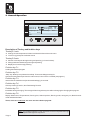
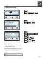
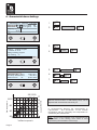
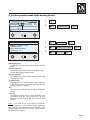
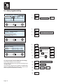
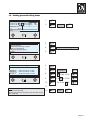
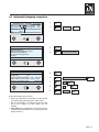
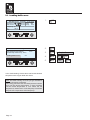
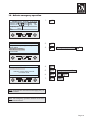
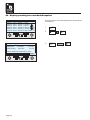
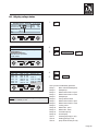
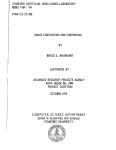
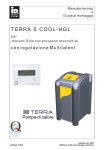
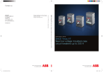
Users manual
TERRA-HGL-Heatpump
heatpump
Expenditure Sept 2005
TERRA-HGL_ Bedienung_Sept05-engl.cdr
Content
1.
General information
Page
1
2.
General operation
2
3.
The display in the main menu
3
4.
Set Tap water temperature
4
5.
Desired room temperature setting Version 1
5
6.
Desired room temperature setting Version 2
6
7.
Characteristic curve setting
7
8.
Room influence setting
8
9.
Set the operation mode of the heat circuits
9
10. Heat program setting
10
11
Mode of bufferloading
11
12. Settings bufferloading
12
13. Settings power blocking times
13
14. Heatpump connection
14
15. Automatic heatpump connection
15
16. Loading buffer once
16
17. ActivateBath-Summer mode
17
18. Activate presence operation
18
19. Activate emergency operation
19
20. Cooling
20
21
21
Cement floor heating program
22. Time and date setting
22
23. Display all temperatures
23
24
24
Display operating hours and switch impulses
25. Display relais status
25
26. Display installation details
26
27. Error display
27
28. Glossary
28
Changes in technology and Design reserve!
IDM-Energiesysteme GmbH, A-9971 Matrei i.O.
TERRA-HGL_Bedienung_Sept05-engl.cdr
1. general information
With the acquisition of this plant you have decided
yourself for a modern and economic heating system
Regular quality controls and improvements,
as well as functional tests in the factory, guarantees
a technically faultless device.
Cleaning:
If required, the Terra heat pump can be cleaned with
a damp cloth. The use of cleansers is not recommended.
Correct EC guidelines
Read these documents attentively.
You will contain important notes and for the sure and
economical operation of the plant.
EC machine guideline (89/392/EEC)
EC low voltage guideline (73/23/EEC)
EC-EMV guideline (89/366/EEC)
Tip for security:
Correct harmonized EN
Installation and maintenance can involve dangers by
high Plant pressures, high temperatures and voltage-carrying Parts and being and must be done by experts.
Heat pumps may only be installed by competent experts and put into operation only by a company which
is trained by IDM energy systems GmbH
EN378
EN60529
EN292/T1/T2
EN294
EN349
EN60335 1/2-40
EN55014
EN55104
For work on the heat pump all safety data in the corresponding documents, the sticker at the heat pump itself and all the other safety regulations have to been
observed.
Correct national norms/guidelines
ÖNORM M7755 2 (Austria)
Transport:
By transport, never incline the thermal pump more
then 15°.
The transportation packing should be removed just after the thermal pump is positioned at the place of installation.
Sound emission:
Terra heat pumps are very quiet in operation due to
their construction.
Nevertheless it is important that the heating room
should be positioned outside of sensitive to noise
living quarter and should be provided with a well closing door closing.
Drying of subfloor or carcass:
The heat pump isn't setup for the increased need of
heat for drying subfloor or carcass.
This must be done by equipment specially designed
for this task.
Important safety reference:
The heat pump is filled with refrigerant. This
Cryogen is non-poisonous and not combustible.
In case of damage however, refrigerant is could flow
out of the plant, and could cause superseding of
oxygen.
Due to open fire, toxic disintegration products can arise
By leaving refrigerant (smell) leave the installation site
immediately leaving and close the door.
Contact the customer service.
Works at and in the equipment are permitted only for
authorized experts
Reference to disturbances and error messages see
Page 20.
Service and maintenance:
A regular maintenance as well as a check and
Care of all important plant parts guarantees at last a
safe and thrifty operation of the plant.
We recommend a contract for maintenance.
Page 1
2. General Operation
IDM-Mainmenue 30/07/02 11:02
20,7°C outdHeat circ A:
°C
21,2°C temp:
Heat circ B:
Buffertemp.: 52°C
Heatpump: on
[1]
32°C,
next
19
F1
D1
F2
F3
F4
F5
F6
D2
Description of Turnkey and funktion keys
Turnkey D 1 sets:
m Change of room temperature inHeat circuit A and/or B out of the main menu
m “Home”-key (press) out of all other menus
Turnkey D 2 sets:
m Choose a menue point through turning and pressing (= Cursor funktion).
m Change and save Data through turning and pressing
m Display the Cursor through pressing.
Funktion key F 1:
Loading the standard program
Funktion key F 2:
“Help”-key: Nearley every Menue has a Help. To leave the Help press key D1.
Announcements status report from the main menue, if the cursor is not visible (see page 27).
Funktion key F 3:
reserved for the maintainance (fundamental settings), pin secured.
Funktion key F 4:
Chimney cleaning Function, also Fast heating Function
Funktion key F 5:
Immediate storage charging. The storage will be charged at any time without changing the Charging time program.
Funktion key F 6:
Display Submenue of Temperatures, Running time, Switch impulses, Running mode, emergancy run, Bath Summer
mode and Machine Data.
Terms, which are underlined, are more near described on page 28!
Note: In principle all attitudes on the regulation can be accomplished through
turn and press of the right turn-key D2 to.
Page 2
3. The Display in the Main menu
Sunshade is displayed in Summer-mode
Shows the actual outside temperature
Shows the Day and Time
Shows the heating circuit operation mode:
Heating Circuit Operation with Nominaltemp.
Heating Circuit Operation with temperature saving
Pump in operation
Heat Circuit Operation in Heating program
21,7°C Shows the measured room temperaturewith
attached ambient temperature feeler
for each heat circuit. If no space temperature
sensor is attached or no space influence
defined, 0,0°C is indicated here..
IDM-Mainmenue 30/07/02 11:02 clock
20,7°C outdHeat circ A:
°C
21,2°C temp:
Heat circ B:
Heatpump: on
Buffertemp.: 52°C
[1]
32°C, Contact extern closed
next
19
Announcement of the current heat pump status (in/out),
the heat pump stage ([1] and ev. [2]), and of the
Heatpump temperature.
“Tab” is shown if buffer is loading for domestic water
Indicate to the buffer temperature (feeler 6), if an
appropriate feeler is attached.
Announcement "contact externally closed", if this
contact is used and is closed. With open telephone
contact the field is empty. To use of the contact see
description of function.
Error messages appear in the grey deposited field in the
display. Closer description see page 24.
If a heating circle runs in the cooling-mode, appears
here "cool"
Note: If the regulation is not served longer than 1 minute in a submenu , the announcement jumps again
in the main menue (excluded with announcement of
the temperatures)
Explanation of the indication symbols:
D1
Turnkey D1 press confirms inputs
D1
Turnkey D1 turn around the cursor
to place and/or to change
attitudes
Applies also to Turnkey D2!
Page 3
4. Set Tap water temperature
IDM-Mainmenu 30/07/00 11:02 clock
Heat circ A:
Heat circ B:
Heatpump: on
[1]
32°C,
next
20,7°C outd21,2°C temp:
D1
19
°C
1.
D2
2.
D2
3.
D2
4.
D2
5.
D2
6.
D2
7.
D2
desired domestic water temp.
8.
D2
47°C
9.
D2
back
next
D2
next
D2
D2
Submenu 1- Page 1
General settings
Bufferloading: loading program
Settings bufferloading
Set power blocking times
cooling
back
D1
next
D2
Submenu 1 - Page 2
Settings domesticwater
Cement floor-heating program
Settings domesticwater
D2
back
D1
D2
Expert-Level: domestic water
desired domestic water temp.: 47°C
times for loading buffer
should be set!
back
D1
D2
Note: Consider during attitude of the desired water
temperature that also the memory load time should be
accordingly changed.
Page 4
D2
5. Desired room temperature (Nominaltemperatur) desire - Version 1
IDM-Mainmenu 30/07/00 11:02 clock
Heat circ A:
Heat circ B:
Heatpump: on
[1]
32°C,
next
20,7°C outd21,2°C temp:
D1
19
22°C
20°C
D1
D1
2.
D1
for Heat circ A:
D1
21°C
D1
for Heat circ B:
D1
19°C
°C
3.
D2
roomtemperature desired
for Heat circ A:
for Heat circ B:
D1
D2
roomtemperature desired
for Heat circ A:
for Heat circ B:
1.
4.
22°C
20°C
5.
D1
D2
Page 5
6. Desired room temperature (Nominaltemperatur) desire - Version 2
IDM-Mainmenu 30/07/00 11:02 clock
Heat circ A:
Heat circ B:
Heatpump: on
[1]
32°C,
next
20,7°C outd21,2°C temp:
D1
19
°C
1.
D2
2.
D2
3.
D2
4.
D2
5.
D2
6.
D2
function: heating program
constant at: 35°C
settings heating program
non freezing: on
back
D1
Heat.circ. A
Caract. curve:
10
room temp. day: 22°C,
flow temp. desired: 35°C,
influence room:
off
back
D2
next
next
D2
night: 16°C
- act: 35°C
quota: 100%
7.
8.
D2
9.
The temperature “Night” sets the night and out of
Heating periods temperature (“always low level”)
Note: If you set the night temperature on 8°C, the
heating circuit will be switched off during the night.
Except for “Non freeze function”.
Seite 6
D2
D2
Heat.circ. A
D1
Heat circ A / B:
room temp. day
D2 20°C
D2
night
D2
8°C
D2
back
D2
D2
D2
D2
7. Room influence setting
IDM-Mainmenu 30/07/00 11:02 clock
Heat circ A:
Heat circ B:
Heatpump: on
[1]
32°C,
next
20,7°C outd21,2°C temp:
D1
19
°C
1.
D2
2.
D2
3.
D2
4.
D2
5.
D2
6.
D2
D2
D2
Heat.circ. A
function: heating program
constant at: 35°C
settings heating program
non freezing: on
back
D1
Heat.circ. A
Caract. curve:
10
room temp. day: 22°C,
flow temp. desired: 35°C,
influence room:
off
back
D2
next
next
D2
night: 16°C
- act: 35°C
quota: 100%
7.
8.
D1
Heat circ A / B:
D2
9.
influence room
D2
D2 on
D2
quota
D2
98%
D2
back
D2
D2
D2
Under “Quota” you can set how strong the control
should react onto the room temperature:
- Influence small (<100%) small influence of room
temperature onto the heating
- Influence big (>100%) big influence of room
temperature onto the heating
If the room sensor is inside a room with an extra heat
source, (e.g. stove) you should set a
small quota. The room temperature of that room effects
all the other rooms connected to the heat circuit
Note: The room influence can only be switched on
if it’s switched on in the service menu
Page 7
8. Characteristic Curve Settings
IDM-Mainmenu 30/07/00 11:02 clock
Heat circ A:
Heat circ B:
Heatpump: on
[1]
32°C,
next
20,7°C outd21,2°C temp:
D1
19
°C
function: heating program
constant at: 35°C
settings heating program
non freezing: on
back
D1
night: 16°C
- act: 35°C
quota: 100%
5
Page 8
10
0
-10 -20°C
Außentemperatur
Outside temperature
Curve Steepness
11
Steilheit der Kennlinie
Vorlauftemperatur
flow temperature
17
14
2
20
20
3.
D2
4.
D2
5.
D2
6.
D2 8
7.
D2
D2
Heat circ. A / B:
D2
next
D2
caract curve
back
D2
D2
D2
8
40
D2
next
25 23 20
60
2.
D2
Heat.circ. A
Caract. curve:
10
room temp. day: 22°C,
flow temp. desired: 35°C,
influence room:
off
back
80°C
D2
D2
Heat.circ. A
D1
1.
Note: If the appropriate heating circle is defined in the
Service menue as floor or wall heating circle, can be
adjusted with characteristic maximally 10!
In accompanying diagram the characteristic is
represented.
The connection of the outside
temperature with the necessary flow temperature is
specified by the characteristic.
Note: For the correct attitude of the characteristic the
interpretation of the heating must admit or must
requested by the Installateur if necessary!
9. Set the operation mode of the Heating Circuits
IDM-Mainmenu 30/07/00 11:02 clock
Heat circ A:
Heat circ B:
Heatpump: on
[1]
32°C,
next
20,7°C outd21,2°C temp:
D1
19
°C
D2
2.
D2
Heat circ A / B:
3.
D2
function
function
4.
D2
always high level
5.
D2
back
D2
D2
Heat.circ. A
function: heating program
constant at: 35°C
settings heating program
non freezing: on
back
D1
1.
next
D2
D2
D2
D2
Heating program:
The Heating for Heat circuit A operate by the set Heat
timing
- Always high level:
The Radiators for Heat circuit A operate always with
nominal Temperature without a drop.
- Always low level:
The Radiators for Heat circuit A always operate with
saving temperature.
- Constant temp:
The heating keeps a constant temperature that is set
in the next line. Summer-Winter switching and the
heating times have no effect
- Off:
Heat circuit A is switched off. Except for Antifreeze
function.
- cooling:
The heating circuit A runs in cooling operation. The
temperature must be set for heat circuit A. The
Mainmenu shows cooling and the pump for heat
circuit A.
Note: In the case of use of the external contact the
mode of operation of the heating circles, depending
upon attitude in the specialist level, can depend on the
switching status of the external contact, sees in addition
the description of function.
Page 9
10. Heat program setting
IDM-Mainmenu 30/07/00 11:02 clock
Heat circ A:
Heat circ B:
Heatpump: on
[1]
32°C,
next
20,7°C outd21,2°C temp:
19
D1
°C
1.
D2
2.
D2
3.
D2
4.
D2
5.
D2
6.
D2
7.
D2
periode 1:
D2
8.
D2
05:00 till 22:00
D2
9.
D2
06:30 till 22:00
D2
10.
D2
06:30 till 20:00
D2
12.
D2
settiings for tuesday
13.
D2
unequal
14.
D2
next
Heat circ A / B:
D2
D2
Heat.circ. A
function: heating program
constant at: 35°C
settings heating program
non freezing: on
back
settings heat program
next
D1
D2
programm for heating circuit A
settings for monday
periode 1
: 06:00 till 22:00 o clock
periode 2
: 00:00 till 00:00 o clock
periode 3
: 00:00 till 00:00 o clock
settings for tuesday unequal
next
D1
D2
11.
To copy the Heat Time from Monday to Tuesday:
The cursor position is onto “unequal”
As soon the Heat times are copied to Tuesday it says
“unequal” again
The Heat time copying from Tuesday to Wednesday
and from Wednesday to Thursday, etc. is done in the
same way like from Monday to Tuesday.
15.
16.
Page 10
...
...
D1
D2
11. Mode of bufferloading
IDM-Mainmenu 30/07/00 11:02 clock
Heat circ A:
Heat circ B:
Heatpump: on
[1]
32°C,
next
20,7°C outd21,2°C temp:
D1
19
°C
1.
D2
2.
D2
3.
D2
4.
D2
bufferloading
5.
D2
loading program
6.
D2
back
D2
next
D2
Submenu 1- Page 1
General settings
Bufferloading: loading program
Settings bufferloading
Set power blocking times
cooling
back
D1
D2
next
D2
D2
D2
Bufferloading Settings
loading program:
The warm water storage is charged after the set
loading times.
always on:
The buffertank will always be loaded as soon the
buffer temperature is below the set Temperature.
- always off:
The buffertank is not been heated to provide warm
water.
Note: In the case of use of the external contact the mode
of operation of the heating circles, depending upon
attitude in the specialist level, can depend on the
switching status of the external contact, sees in addition
the description of function.
Page 11
12. Heat program setting
IDM-Mainmenu 30/07/00 11:02 clock
Heat circ A:
Heat circ B:
Heatpump: on
[1]
32°C,
next
20,7°C outd21,2°C temp:
D1
19
°C
1.
D2
2.
D2
3.
D2
4.
D2
5.
D2
6.
D2
7.
D2
periode 1:
D2
8.
D2
05:00 bis 22:00
D2
9.
D2
06:30 bis 22:00
D2
10.
D2
06:30 bis 20:00
D2
12.
D2
periodes for tuesday
13.
D2
unequal
14.
D2
next
Weiter
D2
D2
Submenu 1- Page 1
General settings
Bufferloading: loading program
Settings bufferloading
Set power blocking times
cooling
back
D1
Settings bufferloading
next
D2
periodes for bufferloading
periodes for monday
periode 1: 06:00 till
periode 2: 00:00 till
periode 3: 00:00 till
periodes for tuesday
D1
22:00 o clock
00:00 o clock
00:00 o clock
unequal
next
D2
11.
To copy the bufferloading time from Monday to
Tuesday:
The cursor position is onto “unequal”
As soon the bufferloading times are copied to
Tuesday it says “unequal” again
The bufferloading time copying from Tuesday to
Wednesday and from Wednesday to Thursday,
etc.is done in the same way like from Monday to
Tuesday.
15.
16.
Page 12
...
...
D1
D2
13. Setting power blocking times
IDM-Mainmenu 30/07/00 11:02 clock
Heat circ A:
Heat circ B:
Heatpump: on
[1]
32°C,
next
20,7°C outd21,2°C temp:
D1
19
°C
D2
2.
D2
3.
D2
4.
D2
5.
D2
6.
D2
7.
D2
periode 1:
D2
8.
D2
05:00 bis 22:00
D2
9.
D2
06:30 bis 22:00
D2
10.
D2
06:30 bis 20:00
D2
D2
back
next
D2
D2
Submenu 1- Page 1
General settings
Bufferloading: loading program
Settings bufferloading
Set power blocking times
cooling
back
D1
next
Set power blocking times
D2
set power blocking periodes
periode 1:
periode 2:
periode 3:
back
D1
1.
06:00 till 22:00 o clock
00:00 till 00:00 o clock
00:00 till 00:00 o clock
D2
11.
Note: The set periodes are valid for every day and
can not set indvidually.
During this periodes the heat pump and the pumps
won´t operate.
12.
...
D2
Page 13
14. Heatpump connection
IDM-Mainmenu 30/07/00 11:02 clock
Heat circ A:
Heat circ B:
Heatpump: on
[1]
32°C,
next
20,7°C outd21,2°C temp:
D1
19
°C
Submenu 1- Page 1
D2
3.
D2
4.
D2
5.
D2
6.
D2
Heatpump
7.
D2
on
8.
D2
back
D2
next
General Settings
D2
D2
Heatpump connection:
! on: The Heatpump is connected and will supply
the buffertank and heating with warm water
! off: The heatpump is disconnected and won´t
supply any warm water to the buffertank or into
heating
Note: In the case of use of the external contact the
heatpump connection, depending upon attitude in
the specialist level, can depend on the switching
status of the external contact, sees in addition the
description of function.
Page 14
2.
next
General Settings
21°
Summer-Winter-change:
Heatpump:
on
autom. Switch on heat p.: yes 30 min
Date / Time: 31 / 07 / 00 - 11:02 o clock
Runtime circulation pump:
3 Minutes
back
D1
D2
D2
General settings
Bufferloading: loading program
Settings bufferloading
Set power blocking times
cooling
back
D1
1.
D2
D2
D2
15. Automatic heatpump connection
IDM-Mainmenu 30/07/00 11:02 clock
Heat circ A:
Heat circ B:
Heatpump: on
[1]
32°C,
next
20,7°C outd21,2°C temp:
D1
19
°C
Submenu 1- Page 1
2.
D2
3.
D2
4.
D2
5.
D2
6.
D2
Autom. Switch on heat p.:
7.
D2
Yes
8.
D2
5 min
9.
D2
back
D2
next
General Settings
next
D2
General Settings
21°
Summer-Winter-change:
Heatpump:
on
autom. Switch on heat p.: yes 30 min
Date / Time: 31 / 07 / 00 - 11:02 o clock
Runtime circulation pump:
3 Minutes
back
D1
D2
D2
General settings
Bufferloading: loading program
Settings bufferloading
Set power blocking times
cooling
back
D1
1.
D2
D2
D2
D2
D2
Automatic heatpump connection:
! Yes: The automation is switched on and the heat
pump will supply the heating with warm water
! no: The automation is switched off and the heat
pump won´t supply any warm water into the
heating
! time setting: the engagement of the heat pump is
retarded at the adjusted time (e.g. although a solar
plant is present)
Page 15
16. Loading buffer once
IDM-Mainmenu 30/07/00 11:02 clock
Heat circ A:
Heat circ B:
Heatpump: on
[1]
32°C,
next
F1
F2
20,7°C outd21,2°C temp:
F4
2.
D2
3.
D2
Loding buffer once
4.
D2
off
5.
D2
back
°C
D2
bufferloading
Actual buffer temperature:
Desired tap water temp.: 48°C
Loading buffer once:
F5
F5
F6
F3
D1
19
1.
47°C
off
D2
back
F1
D1
F2
F3
F4
F5
F6
D2
In the “bufferloading” window the actual and the desired
temperature in the upper buffer are shown.
Note: The buffer loading once can just get activated if
there is a heat pump connected.
The loading just starts if the actual temperature is below
46°C and the desired temperature. It stays activated
until the actual temperature is 10°C above the set
temperature, reaches 55°C or the heatpump is switched
off by the max. temperature of the heatpump.
Page 16
D2
17. Activate Bath-Summer operation mode
IDM-Mainmenu 30/07/00 11:02 clock
Heat circ A:
Heat circ B:
Heatpump: on
[1]
32°C,
next
F1
F2
20,7°C outd21,2°C temp:
F4
F4
3.
D2 Bath-Summer operation:
4.
D2
5.
D2
Bath-Summer operation:
6.
D2
off
7.
D2
back
D2
F5
F6
F3
D1
D2
D2
Submenu 2
F2
2.
°C
Temperatures. operating hours, impulses
Relais Status
Emergancy operation
Bath-Summer operation
Install details
back
F1
F6
F5
F6
F3
D1
19
1.
D2
Bath-Summer operation
Bath-Summer operation: off
In this mode the actual outdoortemperature
is placed by a fix value with 7°C
->heating circuits in work!
D2
back
F1
D1
F2
F3
F4
F5
F6
D2
Note: The Bath- Summer operation mode sets the
outside temperature onto constant 7°C.
This makes it possible that you can use the Heating
also during the summer.
Not used Heating circuits must be switched off.
In the main menu and under the displayed
Temperatures there are no temperatures shown.
All values are 0,0°C
Page 17
18. Activate precence operation
1.
F4
Precence operat.
2.
D2
Precence operat.: off
Changing of the setted heating program
Till the next switch over for the heating
circuit in work
3.
D2
Presence operat.:
4.
D2
off
5.
D2
back
IDM-Mainmenu 30/07/00 11:02 clock
Heat circ A:
Heat circ B:
Heatpump: on
[1]
32°C,
next
F1
D1
F2
F3
20,7°C outd21,2°C temp:
F4
19
°C
F5
F6
D2
back
F1
D1
F2
F3
F4
F5
F6
D2
Note: The Bath- Summer operation mode sets the
outside temperature onto constant 7°C.
This makes it possible that you can use the Heating also
during the summer.
Not used Heating circuits must be switched off.
In the main menu and under the displayed
Temperatures there are no temperatures shown.
Page 18
D2
19. Activate emergency operation
IDM-Mainmenu 30/07/00 11:02 clock
Heat circ A:
Heat circ B:
Heatpump: on
[1]
32°C,
next
F1
20,7°C outd21,2°C temp:
F2
F4
D1
F3
F4
D2
3.
D2
4.
D2
5.
D2
Emergency operation:
6.
D2
off
7.
D2
back
D2
Submenu 2
F2
2.
°C
Temperatures. operating hours, impulses
Relais Status
Emergency operation
Bath-Summer operation
Install details
back
F1
F6
F5
F6
F3
D1
19
1.
Emergency operation:
D2
F5
F6
D2
Emergancy operation
emergency operation: off
Attention: mixers have to be set
in manual mode
back
F1
D1
F2
F3
F4
F5
F6
D2
D2
Note: In this function secures the heat supply, if e.g. a
sensor is fefect.
Note: The emergency operation switches off as soon
you leave the window.
Page 19
20. Cooling
IDM-Mainmenu 30/07/00 11:02 clock
Heat circ A:
Heat circ B:
Heatpump: on
[1]
32°C,
next
20,7°C outd21,2°C temp:
D1
19
°C
Submenu 1- Page 1
D1
D2
3.
D2
4.
D2
5.
D2
6.
D2
Cooling heat circ. A:
7.
D2
locked
D2
8.
D2
next
D2
9.
D2
10.
D2
Next
D2
Cooling
D2
D2
Cooling heat circ. A:
desired Room temperature. HK A:
switch diff. cooling:
desired cooling temp.:
Attention: Dew Point
locked
20,5°C
0,5 K
15°C
D2
next
D2
You also can set individual room temperatures for the
heating circuits. The temperature is only valid for the
cooling not for heating.
You can also set the switch differential and the min.
temperature. The mixer mixes the flow temperature onto
the min. temperature +2K!
Hinweis: To use the cooling function you need to have a
room sensor!
Page 20
2.
next
Cooling heat circ. A:
D1
D2
D2
General settings
Bufferloading: loading program
Settings bufferloading
Set power blocking times
cooling
back
back
1.
11. ...
Cooling heat circ. B:
D2
21. Cement floor heat program
Change as described under point 4 in the
“Submenü 1 - Page 2”
Submenu 1 - Page 2
Settings domesticwater
Cement floor-heating program
back
D1
D2
2.
D2
Cement floor heat. prog.
3.
D2
for heat circ:
4.
D2
heat circ A and B
5.
D2
start temperature
6.
D2
25°C
7.
D2
Cement floor heat. prog.
8.
D2
on
D2
back
D2
D2
Cement floor heating program
for heat circ.: Heat circ.A and B
start temperature: 25°C
cement floor heat progr.: on
desired temp: 25°C, - act: 35°C
off
back
D1
1.
D2
Cement floor heating program:
The Cement floor heating program may be started ac- 9.
cording to DIN EN 1264-4 with Cementsceed at the earliest 21 days and with anhydride or calcium sulfatesceeds at the earliest 7 days after screed putting.
The desired heating circles are heated for 3 days with
25°C. Subsequently, the temperature is increased
daily by 5°C, up to the adjusted maximum temperature
of the heating circles. With this maximum inlet temperature the heating circles are heated for 4 days. At the
end the flow temperature of the desired heating circles
is lowered again around 5°C per day, to 25°C.
While the cement heating are the heating programs for
the heating circles not actively, the heating circles become without sinking claimant.
At the display in the window for the cement heating program the following data are indicated: Desired and actual flow temperature as well as operating status (heating phase, up heating phase, back heating phase,
out).
Sufficient ventilation is important, But draft is to be avoided.
If necessary the cement floor heating program with an
adjustable starting temperature can be started.
D2
D2
D2
D2
It is not guaranteed by the cement floor heating
program that the screed achieved the moisture
content necessary for the voucher-ripe!
Page 21
22. Date and time setting
IDM-Mainmenu 30/07/00 11:02 clock
Heat circ A:
Heat circ B:
Heatpump: on
[1]
32°C,
next
20,7°C outd21,2°C temp:
D1
19
°C
1.
D2
2.
D2
3.
D2
4.
D2
5.
D2
Date/Time
6.
D2
29/06/00-11:02
7.
D2
30/06/00-11:02
8.
D2
30/06/00-11:02
9.
D2
30/07/00-11:02
10.
D2
30/07/00-11:02
11.
D2
30/07/04-11:02
12.
D2
30/07/04-11:02
13.
D2
30/07/04-10:02
14
D2
30/07/04-10:02
15.
D2
30/07/04-10:05
16.
D2
next
D2
D2
General settings
D2
Submenu 1- Page 1
General settings
Bufferloading: loading program
Settings bufferloading
Set power blocking times
cooling
back
D1
next
D2
General Settings
21°
Summer-Winter-change:
Heatpump:
on
autom. Switch on heat p.: yes 30 min
Date / Time: 31 / 07 / 00 - 11:02 o clock
Runtime circulation pump:
3 Minutes
back
D1
Page 22
D2
back
D2
D2
23. Display all temperatures
IDM-Mainmenu 30/07/00 11:02 clock
Heat circ A:
Heat circ B:
Heatpump: on
[1]
32°C,
next
F1
F2
20,7°C outd21,2°C temp:
F4
F4
D1
F2
F3
F4
D2
5.
D2
6.
D2
Temperatures, operating hours...
D2
Overview temperatures
sensor 1: 15°C, sensor 7: 49°C
sensor 2: 39°C, sensor 8: 57,8°C
sensor 3: 34°C, sensor 9: 32°C
sensor 4: 53°C, sensor 10: 20,7°C
sensor 5: 32°C, sensor 11: 21,2°C
sensor 6: 51°C, sensor 12: ext. cont
F1
3.
F5
F6
F3
D1
D2
D2
Temperatures. operating hours, impulses
Relais Status
Emergancy operation
Bath-Summer operation
Install details
back
F2
2.
°C
Submenu 2
F1
F6
F5
F6
F3
D1
19
1.
F5
F6
This window displays all temperatures
Fühler 1: outside
Fühler 2: flow heatpump
Fühler 3: return heatpump
Fühler 4: brine-/groundwaterreturn
Fühler 5: flow heat circuit A
Fühler 6: buffertemperature
Fühler 7: domestic water
Fühler 8: flow HGL
Fühler 9: flow heat circuit B
Fühler 10: room heat circuit A
Fühler 11: room heat circuit B
Fühler 12: ext. contact
D2
Note: The sensors 4, 6, 7, 9, 10 and 11 just shows a
temperature if there is a sensor connected.
Sensor 12 always shows ext. cont.
Page 23
24. Display operating hoers and Switch impulses
Go to the window “overview temperatures” as described
in chapter 23.
Overview temperatures
sensor 1: 15°C, sensor 7: 49°C
sensor 2: 39°C, sensor 8: 57,8°C
sensor 3: 34°C, sensor 9: 32°C
sensor 4: 53°C, sensor 10: 20,7°C
sensor 5: 32°C, sensor 11: 21,2°C
sensor 6: 51°C, sensor 12: ext. cont
F1
D1
F2
F4
Operating hourand switch Impulses
112 Imp.
134 Imp.
41 Imp.
medium heatpump temperature: 38°C.
back
D1
Page 24
F2
F3
2.
D2
3.
D2
D2
D2
heatpump 1:
87,5 Std.,
heatpump 2:
152,0 Std.,
buffer loading:
25,3 Std.,
F1
D2
F5
F6
F3
1.
F4
F5
F6
D2
back
D2
25. Display relays status
IDM-Mainmenu 30/07/00 11:02 clock
Heat circ A:
Heat circ B:
Heatpump: on
[1]
32°C,
next
F1
F2
20,7°C outd21,2°C temp:
F4
Relais Status
Rel 7: off
Rel 8: off
Rel 9: off
Rel 10: on
Rel 11: off
Rel 12: off
off
on
off
off
on
on
F1
D1
F2
F3
3.
D2
4.
D2
5.
D2
Relay Status
D2
F5
F6
F3
D1
Rel 1:
Rel 2:
Rel 3:
Rel 4:
Rel 5:
Rel 6:
F4
D2
D2
Submenu 2
F2
2.
°C
Temperatures. operating hours, impulses
Relay Status
Emergancy operation
Bath-Summer operation
Install details
back
F1
F6
F5
F6
F3
D1
19
1.
F4
D2
Rel 13: off
Triac 1:
0
Triac 2: 10000
Triac 3: 10000
zurück
F5
F6
D2
Note: the triac1 to 3 are depending on the rpm.
Max rpm = 10000, 0 = off
back
Here you can see all Relay positions:
Relay 1:
Brine-/Groundwaterpump
Relay 2:
Heatpump 1
Relay 3:
Mixer Heat circuit A - open
Relay 4:
Mixer Heat circuit A - close
Relay 5:
Heatpump 2
Relay 6:
Pump Heat circuit B
Relay 7:
Mixer Heat circuit B - open
Relay 8:
Mixer Heat circuit B - close
Relay 9:
cooling valve
Relay 10:
Mixer HGL - open
Relay 11:
Mixer HGL - close
Relay 12:
circulation pump
Relay 13:
error display
Triac 1:
exchanger pump (0 = off)
Triac 2:
loading pump (0 = off)
Triac 3:
pump heat circuit A (0 = off)
Page 25
26. Display installation details
IDM-Mainmenu 30/07/00 11:02 clock
Heat circ A:
Heat circ B:
Heatpump: on
[1]
32°C,
next
F1
F2
20,7°C outd21,2°C temp:
F4
F4
WP 04 01 07 HGL
02-07-01
1234567890
back
F1
D1
F2
F3
F4
F5
F6
D2
Following information are shown:
- program version
- start up date
- service telephone number
In case of a malfunction you can ring for service
Page 26
D2
4.
D2
5.
D2
Installation details
D2
Install details
Program version:
Start up date:
Telefone service :
3.
F5
F6
F3
D1
D2
D2
Submenu 2
F2
2.
°C
Temperatures. operating hours, impulses
Relay Status
Emergancy operation
Bath-Summer operation
Install details
back
F1
F6
F5
F6
F3
D1
19
1.
back
D2
27. Error Display
A Varity of errors can be recognised and displayed by the
control unit..
The red LED shines in case of an error. The illustration
shows the position of the displayed error.
Displayed Errors:
- “1” High pressure: The heat pump was switched off by
the High pressure switch. At more than 3 switches off this
way in 24 hours the heat pump is blocked and has to be
switched off and back on by the main switch.
- “2” Low Pressure: The heat pump was switched off by
the Low pressure switch. At more than 3 switches off this
way in 24 hours the heat pump is blocked and has to be
switched off and back on by the main switch.
- “3” Thermo relais error: The heat pump was switched
off by the Thermo relay switch (Motor protection). At
more than 3 switches off this way in 24 hours the heat
pump is blocked and has to be switched off and back on
by the main switch.
-“4” Ground water error: The Groundwater
temperature is to low. After a temperature increase the
Heat pump switches back on automatically.
- “5” Heat Pump power: The Heat pump is operating for
more than 180 minutes without increasing the
temperature. As soon the temperature increases the
Heat Pump switches back on.
- “6” free
IDM-Hauptmenü 30/07/00 11:02 Uhr
Heizkreis A:
Heizkreis B:
Wärmepumpe: ein
[1]
32°C,
weiter
F1
F2
20,7°C Außen21,2°C temp:
F4
°C
F5
F6
F3
D1
19
D2
The red LED shines in case of an error.
The illustration shows the position of the displayed
error..
NOTE:
The errors No. 1, 2 and 3 can be acknowledged by
out and restarting of the heatpump.
The
announcement of the other errors expires, as soon
as the error cause is eliminated.
In the "status report" the arisen errors can also later be
queried. In addition in the main menue turn the cursor
from the window and press the key F2. The status
report remains also after switching off of the heatpump.
Status Report
19.12.2003 21:23 Alarm
High pressure
15.12.2003 16:14 Alarm
Thermo relais error
Page 00
-“7” Sensor out of order: One of the necessary sensors
is not working. You can find out which by going to
“overview temperatures” (page 17)
F1
- “8” check Heat Pump: The relation between operation
hours and switch impulses is bad.
D1
F2
F3
F4
F6
F5
D2
- “9” Gap: The gap between flow and return temperature
of the heat pump is too big. Check mixers.
- “10” Heat Pump Over temperature: The heat pump
was switched off by the Max. temperature threshold and
will switch back on as soon the temperature reaches
49°C.
Page 27
28. Glossary
Nominaltemperature: Desired temperature during the adjusted heat times (usually during the daily),
standard attitude = 20°C..
Nominaloperation: The respective heating circuit is operated in such a way that in the appropriate areas the
nominal temperature (computational) adjusts itself.
Nominaloperation time:That time, in which the nominal temperature for the heating is valid
(standard: 6:00 till 22:00h )
Safetemperature:
Desired room temperature out of the desired heating times (normally during the night),
standard attitude = 16°C
The respective heating circuit is operated in such a way that in the appropriate areas the
nominal temperature (computational) adjusts itself.
Safeoperation time: That time, in which the save-temperature for the heating is valid. Can be adjusted not
directly, but arises as a result of the attitude of the nominal operation time.
Heat program:
In the heating program the nominal operating times are adjusted ,then also the
saving periods of operation are specified defined. The heating program can be stopped
for each heating circle separately.
Heat time:
equal with nominaloperat time
Safeoperation:
Constanttemperature:Desired temperature for the adjusted heating circuit, indipendend from the temperature
outdoor, from heatprogram and from Summer-Winter-change.
Caracteristic curve: Coleration between the outdoor temperature and the flow temperature from heating.
Curve steepness:
Individual attitude of the heat curve, a higher attitude causes higher flow temperatures.
flow temperature:
The temperature, the respective heat circuit is provided. Indipendedend from the function
of the heat circuit(norm-, safe operation), from outdoor temperature, from the caracteristic
curve and from the room influence.
The acutal room temperature will be considered for the calculation of the flowtemperaure from
the heating circuit
- room to warm: flowtemperature decrease
- room to cold: flowtemperature increase
Room influence:
Room influence -quota:A higher attitude, sets a stronger reaction of the control onto the room temperature
Buffer loading program: Times ,when the buffer will be loaded.
Buffer loading time: In this desired time the buffer will be loaded if necessary, out of this time it is not possible to
charge the buffer.
Power blocking times: Some power suppliers block the main currency at different times. In this times the heat pump
won´t operate. The times can be set, that the control reacts in the right way.
Page 28