1
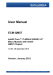
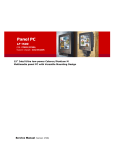
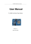
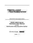
ECM-US15WP
3.5" Intel® Atom™ processor Z510P / Z530P Micro Module
Quick Installation Guide
1st Ed – 11 September 2009
Part No. 2017381800R
ECM-US15WP Quick Installation Guide
FCC Statement
THIS DEVICE COMPLIES WITH PART 15 FCC RULES. OPERATION IS
SUBJECT TO THE FOLLOWING TWO CONDITIONS:
(1) THIS DEVICE MAY NOT CAUSE HARMFUL INTERFERENCE.
(2) THIS DEVICE MUST ACCEPT ANY INTERFERENCE RECEIVED INCLUDING
INTERFERENCE THAT MAY CAUSE UNDESIRED OPERATION.
THIS EQUIPMENT HAS BEEN TESTED AND FOUND TO COMPLY WITH THE LIMITS
FOR A CLASS "A" DIGITAL DEVICE, PURSUANT TO PART 15 OF THE FCC RULES.
THESE LIMITS ARE DESIGNED TO PROVIDE REASONABLE PROTECTION AGAINST
HARMFUL INTERFERENCE WHEN THE EQUIPMENT IS OPERATED IN A
COMMERCIAL ENVIRONMENT. THIS EQUIPMENT GENERATES, USES, AND CAN
RADIATE RADIO FREQUENCY ENERGY AND, IF NOT INSTATLLED AND USED IN
ACCORDANCE WITH THE INSTRUCTION MANUAL, MAY CAUSE HARMFUL
INTERFERENCE TO RADIO COMMUNICATIONS.
OPERATION OF THIS EQUIPMENT IN A RESIDENTIAL AREA IS LIKELY TO CAUSE
HARMFUL INTERFERENCE IN WHICH CASE THE USER WILL BE REQUIRED TO
CORRECT THE INTERFERENCE AT HIS OWN EXPENSE.
Notice
This guide is designed for experienced users to setup the system within the shortest time.
For detailed information, please always refer to the electronic user's manual.
Copyright Notice
Copyright © 2009 Avalue Technology Inc., ALL RIGHTS RESERVED.
No part of this document may be reproduced, copied, translated, or transmitted in any form
or by any means, electronic or mechanical, for any purpose, without the prior written
permission of the original manufacturer.
A Message to the customer
Avalue Customer Services
Each and every Avalue’s product is built to the most exacting specifications to ensure
reliable performance in the harsh and demanding conditions typical of industrial
environments. Whether your new Avalue device is destined for the laboratory or the factory
floor, you can be assured that your product will provide the reliability and ease of operation
for which the name Avalue has come to be known.
2 ECM-US15WP Quick Installation Guide
Quick Installation Guide
Your satisfaction is our primary concern. Here is a guide to Avalue’s customer services. To
ensure you get the full benefit of our services, please follow the instructions below carefully.
Technical Support
We want you to get the maximum performance from your products. So if you run into
technical difficulties, we are here to help. For the most frequently asked questions, you can
easily find answers in your product documentation. These answers are normally a lot more
detailed than the ones we can give over the phone. So please consult the user’s manual
first.
To receive the latest version of the user’s manual; please visit our Web site at:
http://www.avalue.com.tw/
Headquarters and Branch
Avalue Technology Inc.
7F, 228, Lian-cheng Road, Chung Ho City, Taipei, Taiwan
Tel: +886-2-8226-2345
Fax: +886-2-8226-2777
Information: [email protected]
Service: [email protected]
Avalue USA
Avalue Technology Inc.
Avalue Europe
Avalue Europe A/S
200 Tornillo Way, Suite 210, Tinton Falls,
Moelledalen 22C, 3140
NJ 07712
Aalsgaarde, Denmark
Tel: +1-732-578-0200
Tel: +45-7025-0310
Fax: +1-732-578-0250
Fax:+45-4975-5026
Information: [email protected]
Information: [email protected]
Service: [email protected]
Service: [email protected]
BCM Advanced Research
Avalue China
Avalue Technology Inc.
BCM Advanced Research
an Avalue Company
Room 805, Building 9,No.99 Tianzhou Rd.,
7 Marconi, Irvine, CA92618
Caohejing Development Area,
Tel: +1-949-470-1888
Xuhui District, Shanghai
Fax: +1-949-470-0971
Tel: +86-21-5169-3609
Information: [email protected]
Fax:+86-21-5445-3266
Web: www.bcmcom.com
Information: [email protected]
Service: [email protected]
ECM-US15WP Quick Installation Guide 3
ECM-US15WP Quick Installation Guide
1. Getting Started
1.1 Safety Precautions
Warning!
Always completely disconnect the power cord from your
chassis whenever you work with the hardware. Do not
make connections while the power is on. Sensitive
electronic components can be damaged by sudden power
surges. Only experienced electronics personnel should
open the PC chassis.
Caution!
Always ground yourself to remove any static charge before
touching the CPU card. Modern electronic devices are very
sensitive to static electric charges. As a safety precaution,
use a grounding wrist strap at all times. Place all electronic
components in a static-dissipative surface or static-shielded
bag when they are not in the chassis.
Always note that improper disassembling action could cause damage to the
motherboard. We suggest not removing the heatsink without correct
instructions in any circumstance. If you really have to do this, please contact
us for further support.
1.2 Packing List
Before you begin installing your single board, please make sure that the
following materials have been shipped:
z
1 x Intel® US15WP Micro Module
z
1 x Quick Installation Guide for ECM-US15WP
z
1 x SDVO to VGA daughter board
z
1 x DVD-ROM contains the followings:
—User’s Manual (this manual in PDF file)
— Ethernet driver and utilities
— VGA drivers and utilities
— Audio drivers and utilities
z
1 x Cable set contains the followings:
— 1 x VGA cable (DB 15P(F) – 10P/2.0mm)
— 1 x IDE cable (44-pin, pitch 2.0mm)
— 1 x Serial ATA cables (7-pin, standard)
— 1 x PS/2 Keyboard & mouse Y cable (7-pin, Mini-DIN)
4 ECM-US15WP Quick Installation Guide
Quick Installation Guide
2. Hardware
Configuration
ECM-US15WP Quick Installation Guide 5
ECM-US15WP Quick Installation Guide
2.1 Product Overview
6 ECM-US15WP Quick Installation Guide
Quick Installation Guide
2.2 Jumper and Connector List
You can configure your board to match the needs of your application by setting jumpers. A
jumper is the simplest kind of electric switch.
It consists of two metal pins and a small metal clip (often protected by a plastic cover) that
slides over the pins to connect them. To “close” a jumper you connect the pins with the clip.
To “open” a jumper you remove the clip. Sometimes a jumper will have three pins, labeled 1,
2, and 3. In this case, you would connect either two pins.
The jumper settings are schematically depicted in this manual as follows:
A pair of needle-nose pliers may be helpful when working with jumpers.
Connectors on the board are linked to external devices such as hard disk drives, a
keyboard, or floppy drives. In addition, the board has a number of jumpers that allow you to
configure your system to suit your application.
If you have any doubts about the best hardware configuration for your application, contact
your local distributor or sales representative before you make any changes.
The following tables list the function of each of the board’s jumpers and connectors.
Jumpers
Label
Function
Note
JBAT1
Clear CMOS
3 x 1 header, pitch 2.0mm
JCF1
CF card mode select
3 x 1 header, pitch 2.0mm
JTOUCH1
Touch panel mode select
3 x 1 header, pitch 2.0mm
PWR_SEL1
AT/ATX power mode select
3 x 1 header, pitch 2.0mm
RI1
Serial port 1 – Ring, +5V, +12V power
select
3 x 1 header, pitch 2.0mm
RI2
Serial port 2 – Ring, +5V, +12V power
select
3 x 1 header, pitch 2.0mm
ECM-US15WP Quick Installation Guide 7
ECM-US15WP Quick Installation Guide
Connectors
Label
Function
Note
ATXPW1
ATX power connector
3 x 1 wafer, pitch 2.54mm
BBAT1
Battery connector
2 x 1 wafer, pitch 1.25mm
COM1
Serial port1 connector
D-sub 9-pin, male
COM2
Serial port 2 connector
5 x 2 header, pitch 2.0mm
DIO1
Digital Input/ Output connector
10 x 2 header, pitch 2.0mm
IDE1
Primary IDE connector
22 x 2 header, pitch 2.0mm
IR1
IrDA connector
5 x 1 header, pitch 2.54mm
J1
LCD inventer power connector
2 x 1 wafer, pitch 2.54mm
J422/485
Serial port 2 in RS-422/485 mode
connector
3 x 2 header, pitch 2.0mm
JAUDIO1
Audio connector
3 x 2 header, pitch 2.0mm
JBKL1
LCD inverter connector
5 x 1 wafer, pitch 2.0mm
JCD1
CD-ROM audio input connector
4 x 1 header, pitch 2.54mm
JKB/MS1
PS/2 Keyboard & Mouse connector
4 x 2 header, pitch 2.0mm
JLPC1
(Reserved for BIOS programming)
3 x 2 header, pitch 2.0mm
JLVDS1
LVDS connector
HIROSE DF13-200P-1.25C
JSDVO1
SDVD port connector
12 x 2 header, pitch 2.0mm
CON1
(Reserved for BIOS programming)
5 x 2 header, pitch 2.0mm
JUSB1
USB 5&6 connector
5 x 2 header, pitch 2.0mm
JVR1
LCD backlight brightness adjustment
3 x 1 header, pitch 2.0mm
LAN1
RJ-45 Ethernet connector
LED4
Power & HDD indicator
LINEOUT1
Audio out connector
MICPHONE1
MIC connector
PWRBTN1
Power button connector
2 x 1 header, pitch 2.0mm
PWRCON1
Power connector
2 x 2 wafer, pitch 4.2mm
RSTBTN1
Reset button
SATA1
SATA 1 connector
SATA2
SATA 2 connector
SDIO_J1
SDIO connector
5 x 1 header, pitch 2.54mm
SDIO_J2
SDIO connector
6 x 1 header, pitch 2.54mm
USB1
USB 2&3 connector
Double deck
USB2
USB 0&1 connector
Double deck
8 ECM-US15WP Quick Installation Guide
Quick Installation Guide
2.3 Setting Jumpers & Connectors
2.3.1
Clear CMOS (JABT1)
Protect*
Clear CMOS
* Default
2.3.2
CF Card mode select (JCF1)
Master *
Slave
* Default
ECM-US15WP Quick Installation Guide 9
ECM-US15WP Quick Installation Guide
2.3.3
Touch Panel mode select (JTOUCH1)
4/8-Wire*
5-Wire
* Default
2.3.4
AT/ATX power mode select (PWR_SEL1)
AT *
ATX
* Default
10 ECM-US15WP Quick Installation Guide
Quick Installation Guide
2.3.5
Serial port 1 – Ring, +5V, +12V power select (RI1)
Ring*
+5V
+12V
* Default
2.3.6
Serial port 2 – Ring, +5V, +12V power select (RI2)
Ring*
+5V
+12V
* Default
ECM-US15WP Quick Installation Guide 11
ECM-US15WP Quick Installation Guide
2.3.7
2.3.8
ATX power connector (ATXPW1)
Signal
PIN
PSON-
1
GND
2
PS5VSB
3
Signal
PIN
BAT
1
GND
2
Battery connector (BBAT1)
12 ECM-US15WP Quick Installation Guide
Quick Installation Guide
2.3.9
Serial Port 1 connector (COM1)
Signal
2.3.10
PIN PIN
Signal
DCD
1
2
RxD
TxD
3
4
DTR
GND
5
6
DSR
RTS
7
8
CTS
RI
9
PIN PIN
Signal
Serial Port 2 connector (COM2)
Signal
DCD
1
2
RxD
TxD
3
4
DTR
GND
5
6
DSR
RTS
7
8
CTS
RI
9
10
NC
ECM-US15WP Quick Installation Guide 13
ECM-US15WP Quick Installation Guide
2.3.11
Digital Input/ Output connector (DIO1)
Signal
14 ECM-US15WP Quick Installation Guide
PIN PIN
Signal
GPI0
1
2
GPO0
GPI1
3
4
GPO1
GPI2
5
6
GPO2
GPI3
7
8
GPO3
GPI4
9
10
GPO4
GPI5
11
12
GPO5
GPI6
13
14
GPO6
GPI
15
16
GPO7
SMB_CLK
17
18
SMB_DATA
GND
19
20
+5V
Quick Installation Guide
2.3.12
Primary IDE connector (IDE1)
Signal
PIN PIN
Signal
RESET#
1
2
GND
PDD7
3
4
PDD8
PDD6
5
6
PDD9
PDD5
7
8
PDD10
PDD4
9
10
PDD11
PDD3
11
12
PDD12
PDD2
13
14
PDD13
PDD1
15
16
PDD14
PDD0
17
18
PDD15
GND
19
20
NC
PDREQ
21
22
GND
PDIOW#
23
24
GND
PDIOR#
25
26
GND
PIORDY
27
28
GND
PDACK#
29
30
GND
IRQ15
31
32
NC
PDA1
33
34
LID
PDA0
35
36
PDA2
PDCS1#
37
38
PDCS3#
HD_LED1
39
40
GND
+5V
41
42
+5V
GND
43
44
NC
ECM-US15WP Quick Installation Guide 15
ECM-US15WP Quick Installation Guide
2.3.13
2.3.14
IrDA connector (IR1)
Signal
PIN
+5V
1
NC
2
IRRX
3
GND
4
IRTX
5
Audio connector (JAUDIO1)
Signal
16 ECM-US15WP Quick Installation Guide
PIN PIN
Signal
LINEIN_L
1
2
LINEIN_R
GND
3
4
LINE1-JD
SPDIFO
5
6
SPDIFI
Quick Installation Guide
2.3.15
2.3.16
LCD inverter power connector (J1)
Signal
PIN
+12V
1
GND
2
Serial port 2 in RS-422/485 mode (J422/485)
Signal
PIN PIN
Signal
485TX-
1
2
485RX-
485TX+
3
4
485RX+
+5V
5
6
GND
ECM-US15WP Quick Installation Guide 17
ECM-US15WP Quick Installation Guide
2.3.17
LCD Inverter Connector (JBKL1)
Signal
PIN
+12V
1
GND
2
BLK_ON
3
BRIGHT
4
+5V
5
Note:
For inverters with adjustable Backlight function, it is possible to control the LCD
brightness through the VR signal controlled by JVR1. Please see the JVR1 section
for detailed circuitry information.
2.3.17.1 Signal Description – LCD Inverter Connector (JBKL1)
Signal
Signal Description
VR
Vadj = 0.75V ~ 4.25V (Recommended: 4.7KΩ, >1/16W)
BLK_ON
LCD backlight ON/OFF control signal
18 ECM-US15WP Quick Installation Guide
Quick Installation Guide
2.3.18
2.3.19
CD-ROM audio input Connector (JCD1)
Signal
PIN
CD_R
1
GND
2
GND
3
CD_L
4
Keyboard & mouse connector (JKB/MS)
Signal
PIN
PIN
Signal
7
NC
MSCK
6
5
MSDT
+5V
4
3
GND
KBCK
2
1
KBDT
ECM-US15WP Quick Installation Guide 19
ECM-US15WP Quick Installation Guide
2.3.20
LVDS connector (JLVDS1)
Signal
PIN PIN
Signal
GND
2
1
GND
LCDS_0-
4
3
LCDS_0+
LCDS_1-
6
5
LCDS_1+
LCDS_2-
8
7
LCDS_2+
LCDS_3-
10
9
LCDS_3+
LCDS_CLK- 12
11 LCDS_CLK+
GND
14
13
GND
I_SCL
16
15
I_SDA
+5V
18
17
+3.3V
+5V
20
19
+3.3V
Note:
Mating Connector: HIROSE DF13-20DS-1.25C
2.3.21
USB 5&6 connector (JUSB1)
Signal
20 ECM-US15WP Quick Installation Guide
PIN PIN
Signal
+5V
1
2
GND
DN6
3
4
GND
DP6
5
6
DP5
GND
7
8
DN5
GND
9
10
+5V
Quick Installation Guide
2.3.22
2.3.23
LCD backlight brightness adjustment (JVR1)
Signal
PIN
+5V
1
VR
2
GND
3
Power connector (PWRCON1)
Signal
PIN PIN
Signal
VIN
3
4
VIN
GND
2
1
GND
ECM-US15WP Quick Installation Guide 21
ECM-US15WP Quick Installation Guide
2.3.24
2.3.25
SDIO connector (SDIO_J1)
Signal
PIN
+3.3V
1
WP
2
CD
3
DATA1
4
DATA0
5
Signal
PIN
GND
1
PWR
2
CLK
3
CMD
4
DATA3
5
DATA2
6
SDIO connector (SDIO_J2)
22 ECM-US15WP Quick Installation Guide
Quick Installation Guide
2.3.26
2.3.27
Touch panel connector (TOUCH1)
Signal
PIN
X+
1
X-
2
Y+
3
SENSE
4
X+
5
X-
6
Y+
7
Y-
8
GND
9
SDVO port connector (JSDVO1)
Signal
PIN PIN
Signal
+12V
1
2
SDVO_CLK
+5V
3
4
SDVO_CLK#
+3.3V
5
6
SDVO_BLUE
DVO_SEL1
7
8
SDVO_BLUE#
DVO_SEL2
9
10
SDVO_GREEN
GND
11
12
SDVO_GREEN#
GND
13
14
SDVO_RED
SDVO_REST
15
16
SDVO_RED#
SDVO_INIT
17
18
SDVO_TVCLKIN
SDVO_INIT#
19
20 SDVO_TVCLKIN#
SDVO_STALL
21
22
SDVO_STALL# 23
SDVO_CTRCLK
24 SDVO_CTRDATA
ECM-US15WP Quick Installation Guide 23
ECM-US15WP Quick Installation Guide
2.3.27.1
SDVO to DVI/ LVDS/ CRT
SDVO to DVI (V_DVI1)
Signal
PIN PIN
SDVO to LVDS (V_LVDS1)
Signal
Signal
PIN PIN
Signal
+5V
2
1
TDC0N
+5V
2
1
+3.3V
GND
4
3
TDC0P
+5V
4
3
+3.3V
NC
6
5
NC
SPDATA
6
5
SPCLK
NC
8
7
NC
GND
8
7
GND
GND
10
9
TDC1N
YA0P
10
9
YA1P
SDDDC
12
11
TDC1P
YA0M
12
11
YA1M
SCDDC
14
13
NC
GND
14
13
GND
GND
16
15
NC
YA2P
16
15
YA3P
TLCN
18
17
TDC2N
YA2M
18
17
YA3M
TLCP
20
19
TDC2P
GND
20
19
GND
YA4P
22
21
YA5P
YA4M
24
23
YA5M
GND
26
25
GND
YA6P
28
27
YA7P
YA6M
30
29
YA7M
GND
32
31
GND
CLK1P
34
33
CLK2P
CLK1M
36
35
CLK2M
Signal
GND
38
37
GND
+12V
40
39
+12V
SDVO to CRT (V_VGA1)
Signal
PIN PIN
HS_VGA
10
9
VS_VGA
SDT_DDC
8
7
GND
SCK_DDC
6
5
CRT_B_VGA
GND
4
3
CRT_G_VGA
+5V
2
1
CRT_R_VGA
24 ECM-US15WP Quick Installation Guide