1
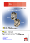
Rotary Encoders Linear Encoders Motion System Translation of the original manual Explosion Protection Enclosure AEV65 II 3 G Ex nAc IIC T6 X II 3 D Ex tc IIIC T85°C IP64 X • Basic safety instructions • Intended use • Product description • Technical data • Explosion protection characteristics • Assembly TR - ECE - BA - GB- 0103 - 01 Explosion protection enclosure AEV65 with integrated measuring system series CEV65 07/18/2013 User manual TR-Electronic GmbH D-78647 Trossingen Eglishalde 6 Tel.: (0049) 07425/228-0 Fax: (0049) 07425/228-33 E-mail [email protected] http://www.tr-electronic.de Copyright This manual, including the therein contained images, is protected by copyright. Third party usage of this manual, which deviates from copyright provisions, is prohibited. Reproduction, translation as well as electronic and photographic archiving or modification requires the author's written authorization. Infringements will lead to liability for damage compensation. The right to amendment is reserved The right to make any changes in the interest of technical progress is reserved. Document information Edition-/Rev.-Date: Document-/Rev.-No.: File name: Author: 07/18/2013 TR - ECE - BA - GB- 0103 - 01 TR-ECE-BA-GB-0103-01.DOC MÜJ Text Cursive or bold text represents the title of a document or is used for emphasis. Courier-text shows text which is visible on the display or screen as well as software menu-selections. ″< > ″ refers to keys on your computer keyboard (e.g. <RETURN>). TR-Electronic GmbH 2013, All Rights Reserved Page 2 of 28 Printed in the Federal Republic of Germany TR - ECE - BA - GB- 0103 - 01 07/18/2013 Table of contents Table of contents Table of contents ................................................................................................................................ 3 Amendment-index .............................................................................................................................. 5 1 General ............................................................................................................................................. 6 1.1 Scope ...................................................................................................................................... 6 1.2 Relevant directives and standards ......................................................................................... 7 1.3 Used abbreviations / Terms .................................................................................................... 8 1.4 Product description ................................................................................................................. 8 2 Basic safety instructions ................................................................................................................ 9 2.1 Symbol- and note definition .................................................................................................... 9 2.2 Obligation of the operator prior to commissioning .................................................................. 10 2.3 General dangers with the use of this product ......................................................................... 10 2.4 Intended use ........................................................................................................................... 11 2.5 Non-intended use ................................................................................................................... 11 2.6 Warranty and liability .............................................................................................................. 12 2.7 Organizational measures ........................................................................................................ 12 2.8 Personnel selection and -qualification; basic obligations ....................................................... 13 2.8.1 Electrical installations design, device selection and erection ................................. 13 2.8.2 Inspection, maintenance and repair ....................................................................... 13 2.9 First commissioning / Commissioning .................................................................................... 14 2.10 Assembly, installation and dismantling ................................................................................. 14 2.11 Inspection, maintenance and repair ..................................................................................... 15 2.12 Special conditions for safe use, marking "X" ........................................................................ 15 3 Transport / Storage ......................................................................................................................... 16 4 Technical data.................................................................................................................................. 17 4.1 Power supply .......................................................................................................................... 17 4.2 Mechanical characteristics ..................................................................................................... 17 4.3 Environmental conditions........................................................................................................ 17 4.4 Enclosure materials ................................................................................................................ 18 4.5 Explosion protection characteristics ....................................................................................... 19 4.5.1 Ex-labeling, gas ...................................................................................................... 19 4.5.2 Ex-labeling, dust ..................................................................................................... 20 5 Assembly .......................................................................................................................................... 21 5.1 Solid shaft ............................................................................................................................... 21 5.1.1 Flange-assembly..................................................................................................... 21 5.1.2 Clamp flange - assembly ........................................................................................ 22 TR-Electronic GmbH 2013, All Rights Reserved Printed in the Federal Republic of Germany 07/18/2013 TR - ECE - BA - GB- 0103 - 01 Page 3 of 28 Table of contents 5.1.3 Fixing clamps - assembly ....................................................................................... 23 5.1.4 Servo clamps - assembly ........................................................................................ 24 6 Equipotential bonding conductor - Connection........................................................................... 25 7 Disposal ............................................................................................................................................ 26 8 Annex ................................................................................................................................................ 27 8.1 EC declaration of conformity .................................................................................................. 27 8.2 Accessories ............................................................................................................................ 28 8.2.1 Interface-specific user manual ................................................................................ 28 TR-Electronic GmbH 2013, All Rights Reserved Page 4 of 28 Printed in the Federal Republic of Germany TR - ECE - BA - GB- 0103 - 01 07/18/2013 Amendment-index Amendment-index Amendment First edition Date Index 06/07/13 00 07/18/13 01 - Working temperature: +70°C to +60°C - Surface-temperature, dust: 80°C to 85°C TR-Electronic GmbH 2013, All Rights Reserved Printed in the Federal Republic of Germany 07/18/2013 TR - ECE - BA - GB- 0103 - 01 Page 5 of 28 General 1 General This -User manual contains all relevant explosion-safety information and includes the following topics: • • • • • • Basic safety instructions Intended use Product description Technical data Explosion protection characteristics Assembly -User manual represents a Since the documentation has a modular structure, this supplement to the other documentation such as for example product data sheets, dimensional drawings and leaflets etc. -User manual is included, but can also be ordered separately. The 1.1 Scope This -User manual applies exclusively to the following explosion protection enclosure series: • AEV65, II 3G Ex nAc IIC T6 X / II 3D Ex tc IIIC T85°C IP64 X The products are labelled with affixed nameplates and are components of a system. It thus applies together with the following documentation: • • • the operator's system-specific operation instructions, this -User manual and the interface-specific user manual TR-Electronic GmbH 2013, All Rights Reserved Page 6 of 28 Printed in the Federal Republic of Germany TR - ECE - BA - GB- 0103 - 01 07/18/2013 General 1.2 Relevant directives and standards The explosion protection enclosure is developed, constructed and finished under compliance with the applicable European- or International standards and directives. EC-Directive 2004/108/EC Electromagnetic compatibility EC-Directive 94/9/EC (ATEX) Equipment and protective systems intended for use in potentially explosive atmospheres EN 61000-6-2: 2005/AC:2005 EMC: Interference immunity EN 61000-6-3: 2007/A1:2011 EMC: Interference emission EN 60079-0: 2009 Explosive atmospheres: General requirements DIN EN 60079-14: 2012 Explosive atmospheres: Electrical installations design, selection and erection EN 60079-15: 2010 Explosive atmospheres: Equipment protection by type of protection "n" EN 60079-31: 2009 Explosive atmospheres: Equipment dust ignition protection by enclosure "t" DIN EN 60529: 2000 Degrees of protection provided by enclosures (IP code) TR-Electronic GmbH 2013, All Rights Reserved Printed in the Federal Republic of Germany 07/18/2013 TR - ECE - BA - GB- 0103 - 01 Page 7 of 28 General 1.3 Used abbreviations / Terms AEV65 Explosion protection enclosure with integrated measuring system of the CEV65 series. CEV Absolut-Encoder with optical scanning ≤ 15 bit resolution, solid shaft design EC European community EMC Electromagnetic compatibility ESD Electro Static Discharge IEC International Electro-technical Commission VDE Verein Deutscher Elektrotechniker (Association of German Electrical Engineers) 1.4 Product description The aluminum explosion protection enclosure with built-in systems and integrated evaluation electronics serves the detection of changes in angle for fixed installations. The changes in angle are transmitted to the evaluation electronics via shaft. The explosion protection enclosure has the ignition protection type • "n": non-sparking operating equipment (potential gas-explosive atmosphere) and • "t": protection by the enclosure (potential dust-explosive atmosphere) Through its manner of construction, the types of ignition protection and additional measures, the enclosure is suitable for the incorporation of non-explosion protected installation devices such as the measuring system of the series CEV65. The construction, as well as the interaction of the individual components and the housing with regards to their possibilities for use in potentially explosive areas, are tested by the company TR-Electronic GmbH and confirmed by identification with the nameplate. TR-Electronic GmbH 2013, All Rights Reserved Page 8 of 28 Printed in the Federal Republic of Germany TR - ECE - BA - GB- 0103 - 01 07/18/2013 Basic safety instructions 2 Basic safety instructions 2.1 Symbol- and note definition means that death or serious injury can occur if the required precautions are not met. means that minor injuries can occur if the required precautions are not met. means that damage to property can occur if the required precautions are not met. indicates important information or features and application tips for the product used. signifies that respective ESD-safety measures according to DIN EN 61340-5-1 supplement 1 are to be observed. TR-Electronic GmbH 2013, All Rights Reserved Printed in the Federal Republic of Germany 07/18/2013 TR - ECE - BA - GB- 0103 - 01 Page 9 of 28 Basic safety instructions 2.2 Obligation of the operator prior to commissioning As an electronic device and for use in potentially explosive areas, the explosion protection enclosure with integrated measuring system is subject to the provisions of the EC-directives EMC and ATEX. Therefore commissioning of the device is only allowed once it has been established that the system/machine in which the device is to be installed, complies with the provisions of the EC-directives EMC and ATEX, the harmonized standards, European standards or the respective national standards. 2.3 General dangers with the use of this product The product, hereafter referred to as equipment is manufactured using the latest technology and according to recognized safety regulations. Nevertheless, nonintended use can cause danger to life and limb of the user or third parties or cause damage to the equipment and other property! Only use the equipment for its intended use, with safety- and danger awareness and in compliance with the -user manual and the interface specific user manual! The operator of an electrical system in a potentially explosive environment should keep the equipment in a proper condition, it should be properly operated and monitored and maintenance- as well as repairs are to be performed. This also includes inspection of the equipment for possible transport damage prior to commissioning. Power connections may not be connected or disconnected with the power engaged. The equipment may not be used in case of defects, as a basic principle it may not be opened and dust deposits > 5 mm must be removed. TR-Electronic GmbH 2013, All Rights Reserved Page 10 of 28 Printed in the Federal Republic of Germany TR - ECE - BA - GB- 0103 - 01 07/18/2013 Basic safety instructions 2.4 Intended use The equipment is used for the detection of angular movements as well as the processing of the measurement data for a downstream control through industrial process- and control procedures. The equipment is a fixed-installation device for use in the Ex-Zone 2 (potentially gasexplosive areas, Il 3 G, device protection level Gc) or 22 (areas with combustible dust II 3 D, device protection level Dc). The assembly takes place through the established attachment possibilities. The electrical data provided on the nameplate, as well as the device category, temperature class etc. for the place of use are to be observed. The operating temperature range of the equipment is -20°C to +60°C. Intended use also includes: • observation of all instructions contained in this interface-specific user manual, -User manual and in the • observation of the nameplate and possible prohibition- or instruction labels on the equipment, • observation of the supplementary documentation e.g. the accompanying product sheet, connector assignments etc., • observation of the machine- or system manufacturer's operating manual, • operating of the equipment within the limits indicated in the technical data ( -User manual/interface-specific user manual). 2.5 Non-intended use Risk of death, bodily injury or damage resulting from non-intended use of the equipment! Since the equipment is not a safety component according to the ECmachine directive, a plausibility test of the measuring-system-values has to be performed through the downstream control. It is compulsory for the operator to incorporate the equipment into their own safety system. The following uses are especially prohibited: in environments with an explosive atmosphere of the Zones 0, 1, 20 and 21 - for medical aims - commissioning of the equipment if the nameplate is no longer readable or is completely missing. TR-Electronic GmbH 2013, All Rights Reserved Printed in the Federal Republic of Germany 07/18/2013 TR - ECE - BA - GB- 0103 - 01 Page 11 of 28 Basic safety instructions 2.6 Warranty and liability The "General terms and conditions" (“Allgemeine Geschäftsbedingungen”) of the company TR-Electronic GmbH apply in general. This will be available to the operator with the contract confirmation or –conclusion at the latest. Warranty- or liability claims with regards to personal- and property damage are excluded, if they are the result of one or more of the following causes: • Non-intended use of the equipment. • Improper assembly, installation, commissioning, programming, maintenance or dismantling of the equipment. • Improperly executed work on the equipment by unqualified personnel. • Operating of the equipment in the presence of technical defects. • The performance of unauthorized mechanical or electrical modifications of the equipment. • The performance of unauthorized repairs • Catastrophic incidents caused by external forces or acts of God. 2.7 Organizational measures • The -User manual must always be kept within reach in the equipment's operating location. • In addition to the -User manual, the generally applicable legal regulations and other mandatory directives for work safety, accident prevention and environmental conservation are to be observed and conveyed. • The applicable national-, site- and system-specific provisions and requirements are to be observed and conveyed. • The operator has the obligation to point out any special operational features and requirements to the personnel. • Before starting work, the personnel responsible for work on or with the equipment -User manual, in particular the chapter on must have read and understood the “Basic safety instructions”. • The nameplate and possible affixed prohibition- or instruction labels on the equipment must be kept in a readable condition. • Do not perform any mechanical or electrical modifications to the equipment, except those which are specifically described in this -User manual. • Repairs may only be performed by the manufacturer, or by a person or body who carries the manufacturer's authorization. TR-Electronic GmbH 2013, All Rights Reserved Page 12 of 28 Printed in the Federal Republic of Germany TR - ECE - BA - GB- 0103 - 01 07/18/2013 Basic safety instructions 2.8 Personnel selection and -qualification; basic obligations 2.8.1 Electrical installations design, device selection and erection The project development of electrical systems, the selection of the devices and the installation in potentially explosive atmospheres may only be performed by persons whose training includes instruction in various types of ignition and installation techniques, applicable regulations and prescriptions as well as general principles of the Zone-classification. The persons must have the relevant competence for the type of work to be performed. The personnel must regularly undergo corresponding further training or courses. For definitions on the knowledge, expertise and competence of the "responsible persons", "manual workers" and "planners", the IEC 60079-14 or DIN EN 60079-14 standards are to be additionally consulted [suppliers e.g. Beuth Verlag GmbH, VDEVerlag GmbH]. 2.8.2 Inspection, maintenance and repair The inspection, maintenance and repair of electrical systems in potentially explosive environments may only be performed by experienced personnel who have also gained knowledge on the various types of ignition and installation procedures, the requirements of the IEC / DIN EN 60079-17 standard, relevant national provisions and company regulations for the system as well as on the general principles of the Zoneclassification during their training. Personnel are to undergo appropriate further training or instruction regularly. Proof of the relevant experience and completed training must be available. For definitions on the knowledge, expertise and competence of the "responsible persons", "expert person with leadership functions" and the "performing personnel", the IEC 60079-17 or DIN EN 60079-17 standards are to be additionally consulted [suppliers e.g. Beuth Verlag GmbH, VDE-Verlag GmbH]. TR-Electronic GmbH 2013, All Rights Reserved Printed in the Federal Republic of Germany 07/18/2013 TR - ECE - BA - GB- 0103 - 01 Page 13 of 28 Basic safety instructions 2.9 First commissioning / Commissioning Prior to the first commissioning the equipment is to be checked regarding its suitability in the respective zone according to its labeling. The values indicated on the nameplate are not to be exceeded. With use of the equipment in areas which are potentially explosive because of dust, a deposit of dust on the top-side which is more than 5 mm thick is not permissible. Here the installation of an additional covering may be required in circumstances where the deposit of dust cannot be reliably avoided. The operational safety of the equipment and the correct functional arrangement of the equipment inside the plant must be checked before commissioning. It may only be used in a clean and undamaged condition. 2.10 Assembly, installation and dismantling With installation and operation of the explosion protective equipment, one should consider protection against hazardous environmental influences which limit the intended use of the equipment. This could be protection against aggressive fluids or weather protection for example. During installation, the IEC 60079-14 and DIN EN 60079-14 as well as other national standards and regulations applicable at the installation site are to be adhered to. The information on the nameplate must be complied with. The assembly of the equipment takes place according to the enclosure's established mounting possibilities, but impacts on the shaft such as from hammer blows are to be avoided. In potentially explosive areas, the equipment's power supply line with mating connector is to be routed in such a way that it is protected from damage and mechanical failure. The maximum connection information on the nameplate must be complied with. For metal enclosures in potentially explosive areas an equipotential line with at least 2 4 mm is required. Wiring work, opening and closing of electrical connections may only be performed with the power switched off. Do not perform any welding work once the equipment has already been wired and switched on. Touching the equipment-connection contacts with bare hands is to be avoided, or the respective ESD-protective measures are to be implemented. TR-Electronic GmbH 2013, All Rights Reserved Page 14 of 28 Printed in the Federal Republic of Germany TR - ECE - BA - GB- 0103 - 01 07/18/2013 Basic safety instructions 2.11 Inspection, maintenance and repair The operator of an electrical system in a potentially explosive environment must keep the equipment in an good condition, operate it properly, monitor it and maintenance and repair work must be performed, also see IEC 60079-17 and DIN EN 60079-17 in this respect. Maintenance work and defect repairs may only be performed by trained professionals. Before the maintenance or repair, the specified safety precautions are to be observed. -User manual and the interfaceThe warning notes on the equipment and in the specific user manual are to be adhered to! The applicable laws and directives are complied with before recommissioning. • The equipment does not require any maintenance by the operator. Nevertheless, inspections must be performed at regular intervals: • Visual inspection - of the enclosure for damages - of the supply line for external damages - for dust deposits • Checking of the connection plug for a tight fit • In case of damages, the equipment is to be taken out of service immediately and to be repaired by the manufacturer! 2.12 Special conditions for safe use, marking "X" The "X" symbol in the labeling of the equipment is used to indicate special application conditions: The equipment's installation location and -manner are generally to be selected in such a way that it is protected from external mechanical influences and in a way that no function limitations can result. Misappropriations of the equipment as • support • tread plank • stirrup • … are prohibited. The mating connector must be secured against accidental disconnection through the use of a screw locking device. TR-Electronic GmbH 2013, All Rights Reserved Printed in the Federal Republic of Germany 07/18/2013 TR - ECE - BA - GB- 0103 - 01 Page 15 of 28 Transport / Storage 3 Transport / Storage Transport – instructions Do not drop the device or allow hard impacts! Only use the original packaging! Inappropriate packaging material may cause damage to the device during transport. Storage Storage temperature: -30 to +80°C Store in a dry place TR-Electronic GmbH 2013, All Rights Reserved Page 16 of 28 Printed in the Federal Republic of Germany TR - ECE - BA - GB- 0103 - 01 07/18/2013 Technical data 4 Technical data 4.1 Power supply Rated Voltage ........................................................ 24 V DC Power consumption ............................................. ≤ 3 W 4.2 Mechanical characteristics Mechanically permissible speed ......................... ≤ 4000 min-1 Shaft load, at the shaft end ................................. ≤ 40 N axial, ≤ 60 N radial Bearing life time .................................................... ≥ 3,9 * 1010 revolutions at Speed ............................................................ ≤ 3000 min-1 Operating temperature .................................. ≤ 60 °C Shaft loading, at the shaft end ...................... ≤ 20 N axial, ≤ 30 N radial Angular acceleration ............................................ ≤ 104 rad/s2 -6 2 Moment of inertia.................................................. typically 2.5 * 10 kg m Start-up torque at 20 °C ....................................... typically 2 Ncm Mass ....................................................................... 0.7 kg 4.3 Environmental conditions Vibration, DIN EN 60068-2-6 ....................... ≤ 100 m/s2, sine 50-2000 Hz Shock, DIN EN 60068-2-27 .......................... ≤ 1000 m/s2, half-sine 11ms EMC Immunity to disturbance, DIN EN 61000-6-2 Transient emissions, DIN EN 61000-6-3 Working temperature .................................. -20 °C…+60 °C Storage temperature ................................... -30 °C…+80 °C, dry Relative humidity, DIN EN 60068-3-4 ......... 98 %, non-condensing 1 1 Protection class ........................................ IP64: Degrees of protection provided by enclosures according to DIN EN 60529 Observe instructions for plug connections / mating plugs, see chapter 2.12 on page 15 TR-Electronic GmbH 2013, All Rights Reserved Printed in the Federal Republic of Germany 07/18/2013 TR - ECE - BA - GB- 0103 - 01 Page 17 of 28 Technical data 4.4 Enclosure materials Aluminum design Enclosure material ..................................... Al Mg Si 0.5 F22 Flange material........................................... EN AW-AlCu6BiPb Shaft, stainless steel .......................................... WN 1.4305, corrosion resistant TR-Electronic GmbH 2013, All Rights Reserved Page 18 of 28 Printed in the Federal Republic of Germany TR - ECE - BA - GB- 0103 - 01 07/18/2013 Technical data 4.5 Explosion protection characteristics 4.5.1 Ex-labeling, gas II 3G Ex nAc IIC T6 X II 3G Ex nAc II C T6 X special conditions Temperature (IEC/CENELEC) Subgroup (IEC/CENELEC) Group (IEC/CENELEC) Ignition protection type (IEC/CENELEC) Labeling (IEC/CENELEC) Device category (ATEX) Device group (ATEX) Ex-labeling (ATEX) Device group................................................ II: potentially gas-explosive areas Device category ........................................... 3G: Zone 2 adequate safety with normal operation Ignition protection type .............................. nAc: non-sparking equipment Ex-Atmosphere cannot be ignited in case of defined malfunction conditions Group ............................................................ II: potentially gas-explosive areas Subgroup ..................................................... C: typical gas: Hydrogen, acetylene Temperature................................................. T6: max. enclosure surface-temperature ≤ 85 °C Special conditions....................................... X: see chapter 2.12 on page 15 TR-Electronic GmbH 2013, All Rights Reserved Printed in the Federal Republic of Germany 07/18/2013 TR - ECE - BA - GB- 0103 - 01 Page 19 of 28 Technical data 4.5.2 Ex-labeling, dust II 3D Ex tc IIIC T85°C IP64 X II 3D Ex tc III C T85°C IP64 X special conditions Type of protection Temperature Subgroup (IEC/CENELEC) Group (IEC/CENELEC) Ignition protection type (IEC/CENELEC) Labeling (IEC/CENELEC) Device category (ATEX) Device group (ATEX) Ex-labeling (ATEX) Device group............................................. II: potentially dust-explosive areas Device category ........................................ 3D: Zone 22 adequate safety with normal operation Ignition protection type ........................... tc: Protection by enclosure with adherence to the type of protection and within the surface temperature limits, Ex-atmosphere cannot be ignited Group ......................................................... III: potentially dust-explosive areas Subgroup .................................................. C: Type of dust: conductive dust Temperature.............................................. T85°C: max. enclosure surface-temperature ≤ 85 °C 2 Protection class ..................................... IP64: Degrees of protection provided by enclosures according to DIN EN 60529 Special conditions.................................... X: see chapter 2.12 on page 15 2 Observe instructions for plug connections / mating plugs, see chapter 2.12 on page 15 TR-Electronic GmbH 2013, All Rights Reserved Page 20 of 28 Printed in the Federal Republic of Germany TR - ECE - BA - GB- 0103 - 01 07/18/2013 Assembly 5 Assembly Dimensions must be taken from the customer-specific drawing Tolerance specifications of the coupling manufacturer are to be adhered to 5.1 Solid shaft The equipment with solid shaft is connected to the drive shaft via an elastic coupling. Deviations in axial and radial direction between the equipment and drive shaft are absorbed by means of the coupling. This avoids excessive loads. Danger of explosion through the use of couplings which are not suitable for use in potentially explosive areas! - Only couplings may be used which are approved for use in potentially explosive areas and which meet the requirements of the defined characteristics, see the chapter “Technical data”, as from page 17. - Adhere to the assembly and operating instructions of the manufacturer. 5.1.1 Flange-assembly The centring collar with proper fit assures the centring of the shaft. Attachment to the machine takes place via bolts in the flange. 1: ATEX-conformant coupling 2: Machine 3: Centring collar Principle Figure 1: Flange-assembly TR-Electronic GmbH 2013, All Rights Reserved Printed in the Federal Republic of Germany 07/18/2013 TR - ECE - BA - GB- 0103 - 01 Page 21 of 28 Assembly 5.1.2 Clamp flange - assembly The centring collar with proper fit assures the centring of the shaft. Attachment to the machine takes place via a clamp flange. 1: ATEX-conformant coupling 2: Clamp flange 3: Centring collar Principle Figure 2: Clamp flange - assembly TR-Electronic GmbH 2013, All Rights Reserved Page 22 of 28 Printed in the Federal Republic of Germany TR - ECE - BA - GB- 0103 - 01 07/18/2013 Assembly 5.1.3 Fixing clamps - assembly The centring collar with proper fit assures the centring of the shaft. Attachment to the machine takes place via 2 fixing clamps, which are mounted with 4 bolts. 1: ATEX-conformant coupling 2: Machine 3: Centring collar 4: Fixing clamps, 2x Principle Figure 3: Fixing clamps - assembly TR-Electronic GmbH 2013, All Rights Reserved Printed in the Federal Republic of Germany 07/18/2013 TR - ECE - BA - GB- 0103 - 01 Page 23 of 28 Assembly 5.1.4 Servo clamps - assembly The centring collar with proper fit assures the centring of the shaft. Atachment to the machine takes place via three servo clamps 1: ATEX-conformant coupling 2: Machine 3: Centring collar 4: Servo clamps, 3x Principle Figure 4: Servo clamps - assembly TR-Electronic GmbH 2013, All Rights Reserved Page 24 of 28 Printed in the Federal Republic of Germany TR - ECE - BA - GB- 0103 - 01 07/18/2013 Equipotential bonding conductor - Connection 6 Equipotential bonding conductor - Connection An equipotential is required for systems in potentially explosive areas. This is to be done with a minimum wire diameter of 4 mm2. (1): M3 attachment bolt (2): Locking element (3): Soldering lug Figure 5: Equipotential bonding conductor - Connection TR-Electronic GmbH 2013, All Rights Reserved Printed in the Federal Republic of Germany 07/18/2013 TR - ECE - BA - GB- 0103 - 01 Page 25 of 28 Disposal 7 Disposal Electronic waste is hazardous waste. The applicable country-specific regulations are to be adhered to for disposal. TR-Electronic GmbH 2013, All Rights Reserved Page 26 of 28 Printed in the Federal Republic of Germany TR - ECE - BA - GB- 0103 - 01 07/18/2013 Annex 8 Annex 8.1 EC declaration of conformity TR-Electronic GmbH 2013, All Rights Reserved Printed in the Federal Republic of Germany 07/18/2013 TR - ECE - BA - GB- 0103 - 01 Page 27 of 28 Annex 8.2 Accessories 490-00101 Info Switchboardmodule PT-6 TR-V-TI-GB-0020 490-00105 Info Switchboardmodule PT-15/2 TR-V-TI-GB-0060 490-00310 USB PC-Adapter V4 Info TR-E-TI-DGB-0074 49-110-xxx Info Fixing clamps/ Servo-clamps TR-V-TI-GB-0400 490-01001 Software- and Support-DVD: - GSD-, EDS-, type- and XML-files + Documentation - Programming-Software - Driver 8.2.1 Interface-specific user manual Document-No.: Description TR-ECE-BA-DGB-0067 Absolute Encoder Series Cxx-65 with SSI interface TR-ECE-BA-DGB-0084 Absolute Encoder Series Cxx-65 with analog interface TR-Electronic GmbH 2013, All Rights Reserved Page 28 of 28 Printed in the Federal Republic of Germany TR - ECE - BA - GB- 0103 - 01 07/18/2013