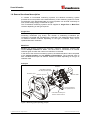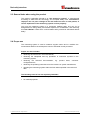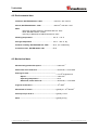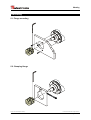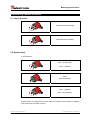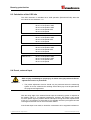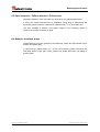
1
User Manual 111-00016
CE-65-S
© TR-Electronic GmbH 2007, All Rights Reserved
Printed in the Federal Republic of Germany
01/10/2007
TR - ECE - BA - DGB - 0059 - 00
Page 27 of 52
TR-Electronic GmbH
D-78647 Trossingen
Eglishalde 6
Tel.: (0049) 07425/228-0
Fax: (0049) 07425/228-33
E-mail: [email protected]
http://www.tr-electronic.de
Copyright protection
This Manual, including the illustrations contained therein, is subject to copyright
protection. Use of this Manual by third parties in contravention of copyright
regulations is forbidden. Reproduction, translation as well as electronic and
photographic archiving and modification require the written content of the
manufacturer. Offenders will be liable for damages.
Subject to amendments
Any technical changes that serve the purpose of technical progress, reserved.
Document information
Release date/Rev. date:
Document rev. no.:
File name:
Author:
01/10/2007
TR - ECE - BA - DGB - 0059 - 00
TR-ECE-BA-DGB-0059-00.DOC
MÜJ
Font styles
Italic or bold font styles are used for the title of a document or are used for
highlighting.
Courier font displays text, which is visible on the display or screen and software
menu selections.
″<
> ″ indicates keys on your computer keyboard (such as <RETURN>).
© TR-Electronic GmbH 2007, All Rights Reserved
Page 28 of 52
Printed in the Federal Republic of Germany
TR - ECE - BA - DGB - 0059 - 00
01/10/2007
Contents
Contents
Contents .............................................................................................................................................. 29
Revision index .................................................................................................................................... 31
1 General information ........................................................................................................................ 32
1.1 Applicability ............................................................................................................................. 32
1.2 Declaration of manufacturer ................................................................................................... 32
1.3 Abbreviations and definitions.................................................................................................. 33
1.4 General functional description ................................................................................................ 34
2 Basic safety instructions................................................................................................................ 35
2.1 Definition of symbols and instructions .................................................................................... 35
2.2 Obligation of the operator before start-up .............................................................................. 35
2.3 General risks when using the product .................................................................................... 36
2.4 Proper use .............................................................................................................................. 36
2.5 Warranty and liability .............................................................................................................. 37
2.6 Organizational measures........................................................................................................ 38
2.7 Personnel qualification; obligations ........................................................................................ 38
2.8 Safety information's ................................................................................................................ 39
3 Transportation / Storage................................................................................................................. 40
4 Technical data.................................................................................................................................. 41
4.1 Electrical characteristics ......................................................................................................... 41
4.2 Environmental data................................................................................................................. 42
4.3 Mechanical data...................................................................................................................... 42
5 Mounting .......................................................................................................................................... 43
5.1 Flange mounting ..................................................................................................................... 43
5.2 Clamping flange...................................................................................................................... 43
6 Installation / Preparation for commissioning ............................................................................... 44
6.1 RS422 Data transmission technology .................................................................................... 44
6.2 Cable definition ....................................................................................................................... 45
6.3 Connection.............................................................................................................................. 46
6.4 Switching on the supply voltage ............................................................................................. 46
7 ASI Interface..................................................................................................................................... 47
7.1 Message format ...................................................................................................................... 47
© TR-Electronic GmbH 2007, All Rights Reserved
Printed in the Federal Republic of Germany
01/10/2007
TR - ECE - BA - DGB - 0059 - 00
Page 29 of 52
7.1.1 Translation table for ASCII-signs / Data bits........................................................... 48
8 Measuring system functions.......................................................................................................... 49
8.1 Count direction........................................................................................................................ 49
8.2 Speed output .......................................................................................................................... 49
8.3 Calculation of the CRC bits .................................................................................................... 50
8.4 Preset, external input.............................................................................................................. 50
8.5 Opto electronic – Failure detection / Failure reset.................................................................. 51
8.6 Behavior at voltage drops ....................................................................................................... 51
9 Causes of faults and remedies ...................................................................................................... 52
© TR-Electronic GmbH 2007, All Rights Reserved
Page 30 of 52
Printed in the Federal Republic of Germany
TR - ECE - BA - DGB - 0059 - 00
01/10/2007
Revision index
Revision index
Revision
First release
Index
01/10/07
00
© TR-Electronic GmbH 2007, All Rights Reserved
Printed in the Federal Republic of Germany
01/10/2007
Date
TR - ECE - BA - DGB - 0059 - 00
Page 31 of 52
General information
1 General information
The User Manual includes the following topics:
•
Basic safety instructions
•
Technical data
•
Mounting
•
Installation
•
Interface / Features
•
Cause of faults and remedies
As the documentation is arranged in a modular structure, this User Manual is
supplementary to other documentation, such as product datasheets, dimensional
drawings, leaflets etc.
The User Manual may be included in the customer's specific delivery package or it
may be requested separately.
1.1 Applicability
This User Manual applies exclusively to the following measuring system series with
ASI interface:
•
CE-65-S, Art.-No.: 111-00016
The products are labelled with affixed nameplates and are components of a system.
The following documentation therefore also applies:
•
•
the operator's operating instructions specific to the system,
this User Manual
1.2 Declaration of manufacturer
The series CE-65-S measuring systems have been developed, designed and
manufactured under observation of the applicable international and European
standards and directives.
A corresponding manufacturer’s
TR-Electronic GmbH.
declaration
can
be
requested
from
The
manufacturer
of
the
product,
TR-Electronic
GmbH
in
D-78647 Trossingen, operates a certified quality assurance system in accordance
with ISO 9001.
© TR-Electronic GmbH 2007, All Rights Reserved
Page 32 of 52
Printed in the Federal Republic of Germany
TR - ECE - BA - DGB - 0059 - 00
01/10/2007
General information
1.3 Abbreviations and definitions
ASI
Asynchronous Serial Interface
CE
Absolute Encoder with optical scanning unit, Solid Shaft
EC
European Community
EMC
Electro Magnetic Compatibility
ESD
Electro Static Discharge
IEC
International Electrotechnical Commission
LSB
Least Significant Byte
MSB
Most Significant Byte
VDE
German Electrotechnicians Association
© TR-Electronic GmbH 2007, All Rights Reserved
Printed in the Federal Republic of Germany
01/10/2007
TR - ECE - BA - DGB - 0059 - 00
Page 33 of 52
General information
1.4 General functional description
In contrast to incremental measuring systems, the absolute measuring system
provides the current position value instantaneously. If this measuring system is moved
mechanically in the deactivated state, the current position can be read out directly as
soon as the voltage supply is switched on again.
The TR absolute measuring systems can be supplied in Single-Turn or Multi-Turn
versions depending on the type required.
Single-Turn
This measuring system resolves a single revolution or turn of the drive shaft into
measuring increments (e.g. 8192). The number of measuring increments per
revolution is recorded and calculated via a code disk. This measured value is output
via different interface modules depending on the type of interface used, and is
repeated after each revolution.
Multi-Turn
Besides the angular positions per revolution, multi-turn measuring systems also
record multiple rotations or turns. The drive shaft is connected to an internal
reduction gear via which the number of revolutions is recorded.
In the case of the multi-turn measuring system, the measured value is thus composed
of the angular position and the Number of Revolutions. The measured value is
also calculated and output via different interface modules depending on the type of
interface used.
Principle
IR-LEDs
Code Disk to identify
the Steps per Revolution
Evaluation Unit
IR-Photo Sensors
Encoder Shaft
Focusing Window
for Opto Electronic
Code Disk to identify the
Number of Revolutions
Figure 1: Measuring system operating principle
© TR-Electronic GmbH 2007, All Rights Reserved
Page 34 of 52
Printed in the Federal Republic of Germany
TR - ECE - BA - DGB - 0059 - 00
01/10/2007
Basic safety instructions
2 Basic safety instructions
2.1 Definition of symbols and instructions
means that death, serious injury or major damage to property
could occur if the stated precautions are not met.
WARNING !
means that minor injuries or damage to property can occur if
the stated precautions are not met.
CAUTION !
indicates important information's or features and application tips
for the product used.
means that appropriate ESD-protective measures are to be
considered according to DIN EN 100 015-1.
(Cause of a potential equalization between body and device-mass
as well as the housing-mass about a high-impedance resistance
(approx. 1 MΩ) e.g. with a commercial ESD wrist strap).
2.2 Obligation of the operator before start-up
In accordance with the EC Machinery Directive, the measuring system is considered
to be a machine part for fitting into a system/machine. Moreover, the conformity of the
measuring system was investigated in respect of the EMC Directive.
It is therefore only permitted to start up the measuring system if it has been
established that the system/machine into which the measuring system is to be fitted
satisfies the provisions of the EC Machinery Directive, the EC EMC Directive, the
harmonized standards, European standards or the corresponding national standards.
© TR-Electronic GmbH 2007, All Rights Reserved
Printed in the Federal Republic of Germany
01/10/2007
TR - ECE - BA - DGB - 0059 - 00
Page 35 of 52
Basic safety instructions
2.3 General risks when using the product
The product, hereinafter referred to as "the measuring system", is manufactured
according to state-of-the-art technology and accepted safety rules. Nevertheless,
improper use can pose a danger to life and limb of the user or third parties, or
lead to impairment of the measuring system or other property!
Only use the measuring system in a technically faultless state, and only for its
designated use, taking safety and hazard aspects into consideration, and observing
this User Manual! Faults which could threaten safety should be eliminated without
delay!
2.4 Proper use
The measuring system is used to measure angular motion and to condition the
measurement data for the subsequent control of industrial control processes.
Proper use also includes:
• observing all instructions in this User Manual,
• observing the nameplate and any prohibition or instruction symbols on the
measuring system,
• observing the enclosed
configurations etc.,
documentation,
e.g.
product
insert,
connector
• observing the operating instructions from the machine or system manufacturer,
• operating the measuring system within the limit values specified in the technical
data.
The following areas of use are especially forbidden:
• in environments where there is an explosive atmosphere
• for medical purposes
© TR-Electronic GmbH 2007, All Rights Reserved
Page 36 of 52
Printed in the Federal Republic of Germany
TR - ECE - BA - DGB - 0059 - 00
01/10/2007
Basic safety instructions
Examples of typical fields of application at industrial process and control
processes:
•
•
•
•
•
•
Transfer machines
Machine tools
Gantry robots
Assembly installations
etc. ...
Everywhere, where rotation or angular movements must be detected for
evaluation
Where there is a danger of physical injury and damage to property arising
from jumps in the position of the measuring system!
WARNING !
-
As the measuring system does not constitute a safety component, a
plausibility check of the measuring system values must be performed
through the subsequent control system.
-
It is mandatory for the operator to integrate the measuring system into his
own safety concept.
2.5 Warranty and liability
The General Terms and Conditions ("Allgemeine Geschäftsbedingungen") of TRElectronic GmbH always apply. These are available to the operator with the Order
Confirmation or when the contract is concluded at the latest. Warranty and liability
claims in the case of personal injury or damage to property are excluded if they
result from one or more of the following causes:
•
Non-designated use of the measuring system.
•
Improper assembly, installation, start-up and programming of the measuring
system.
•
Incorrectly undertaken work on the measuring system by unqualified
personnel.
•
Operation of the measuring system with technical defects.
•
Mechanical or electrical modifications to the measuring systems undertaken
autonomously.
•
Repairs carried out autonomously.
•
Third party interference and Acts of God.
© TR-Electronic GmbH 2007, All Rights Reserved
Printed in the Federal Republic of Germany
01/10/2007
TR - ECE - BA - DGB - 0059 - 00
Page 37 of 52
Basic safety instructions
2.6 Organizational measures
• The User Manual must always be kept accessible at the place of use of the
measuring system.
• In addition to the User Manual, generally applicable legal and other binding
accident prevention and environmental protection regulations are to be observed
and must be mediated.
• The respective applicable national, local and system-specific provisions and
requirements must be observed and mediated.
• The operator is obliged to inform personnel on special operating features and
requirements.
• The personnel instructed to work with the measuring system must have read and
understood the User Manual, especially the chapter “Basic safety instructions”
prior to commencing work.
• The nameplate and any prohibition or instruction symbols applied on the
measuring system must always be maintained in a legible state.
• Do not undertake any mechanical or electrical modifications on the measuring
system, apart from those explicitly described in this User Manual.
• Repairs may only be undertaken by the manufacturer or a facility or person
authorized by the manufacturer.
2.7 Personnel qualification; obligations
• All work on the measuring system must only be carried out by qualified personnel.
Qualified personnel includes persons, who, through their training, experience and
instruction, as well as their knowledge of the relevant standards, provisions,
accident prevention regulations and operating conditions, have been authorized
by the persons responsible for the system to carry out the required work and are
able to recognize and avoid potential hazards.
• The definition of “Qualified Personnel” also includes an understanding of the
standards VDE 0105-100 and IEC 364 (source: e.g. Beuth Verlag GmbH, VDEVerlag GmbH).
• Define clear rules of responsibilities for the assembly, installation, start-up and
operation. The obligation exists to provide supervision for trainee personnel !
© TR-Electronic GmbH 2007, All Rights Reserved
Page 38 of 52
Printed in the Federal Republic of Germany
TR - ECE - BA - DGB - 0059 - 00
01/10/2007
Basic safety instructions
2.8 Safety information's
•
WARNING !
CAUTION !
Destruction, damage or malfunctions of the measuring system !
-
De-energize the system before carrying out wiring work or opening and
closing electrical connections.
-
Do not carry out welding if the measuring system has already been wired up
or is switched on.
-
Ensure that the area around the assembly site is protected from corrosive
media (acid, etc.).
-
Avoid any shocks (e.g. hammer-blow) on the shaft while mounting.
-
Do not open the measuring system.
•
The measuring system contains electrostatically endangered circuit
elements and units which can be destroyed by an improper use.
-
•
Contacts of the measuring system connection contacts with the fingers are to
be avoided, or the appropriate ESD protective measures are to be applied.
Disposal
If disposal has to be undertaken after the life span of the device, the respective
applicable country-specific regulations are to be observed.
© TR-Electronic GmbH 2007, All Rights Reserved
Printed in the Federal Republic of Germany
01/10/2007
TR - ECE - BA - DGB - 0059 - 00
Page 39 of 52
Transportation / Storage
3 Transportation / Storage
Notes on transportation
Do not drop the device or expose it to strong strokes!
Device contains an optical system.
Only use the original packaging!
The wrong packaging material can cause damage to the device during
transportation.
Storage
Storage temperature: -30 to +80°C
Store in a dry place
© TR-Electronic GmbH 2007, All Rights Reserved
Page 40 of 52
Printed in the Federal Republic of Germany
TR - ECE - BA - DGB - 0059 - 00
01/10/2007
Technical data
4 Technical data
4.1 Electrical characteristics
Supply voltage: .............................................. 11-35 V DC
Overvoltage protection
Reverse polarity protection
Overcurrent protection
Current consumption without load: ............ < 150 mA
Total resolution: ............................................ 12 bit
Number of steps / revolution: ...................... 4096 (12 bit)
Number of revolutions: ................................. 1
Transmission: ................................................ twisted and shielded copper cable
ASI Interface
Data transmission: .................................... RS422 (2-wire)
Format: ...................................................... 1 Start bit, 8 Data bits, no parity, 1 Stop bit
Data record: .............................................. 8 signs
Baud rate:.................................................. 4800
Cycle time: ................................................ 26 ms ±500µs
Output code:.............................................. ASCII
Overvoltage protection
Overcurrent protection
Emission protection
Optoelectronics
Infrared light source: ................................. median life 106 hours
Infrared receiver: ....................................... Photo transistor
Inputs
Preset: ....................................................... electronic adjustment
Logic level: ................................................ „0“ < + 2 VDC, „1“ = Supply voltage
Impedance: ............................................... 2.3 kOhm, against 0 V
© TR-Electronic GmbH 2007, All Rights Reserved
Printed in the Federal Republic of Germany
01/10/2007
TR - ECE - BA - DGB - 0059 - 00
Page 41 of 52
Technical data
4.2 Environmental data
Vibration, DIN EN 60068-2-6: 1996 ...................... ≤ 100 m/s2, sine 100 Hz
Shock, DIN EN 60068-2-27: 1995......................... ≤ 250 m/s2, half-sine 11ms
EMC
- Discharge of static electricity, DIN EN 61000-4-2: 2001
- Burst, DIN EN 61000-4-4: 2004
- Immunity to disturbance, DIN EN 61000-6-2: 2001
Working temperature ........................................... -20 °C…+70 °C
Storage temperature ............................................ -30 °C…+80 °C, dry
Relative humidity, DIN EN 60068-3-4: 2002........ 98 %, non condensing
Protection class, DIN EN 60529: 1991 ................ IP 54
4.3 Mechanical data
Mechanically permissible speed................................. ≤ 6.000 min-1
Shaft load, at the shaft end ......................................... ≤ 50 N axial, ≤ 20 N radial
Bearing life time............................................................ ≤ 4 x 10⁸ revolutions at
- Speed .................................................................. ≤ 3.000 min-1
- Operating temperature...................................... ≤ 60°C
- Shaft load, at the shaft end............................... ≤ 25 N axial, ≤ 10 N radial
Angular acceleration .................................................... ≤ 105 rad/s2
-6
2
Momentum of inertia .................................................... typically 5 x 10 Nm/sec
Start-up torque at 20°C ................................................ typically 1 Ncm
Mass............................................................................... typically 0.8 kg
© TR-Electronic GmbH 2007, All Rights Reserved
Page 42 of 52
Printed in the Federal Republic of Germany
TR - ECE - BA - DGB - 0059 - 00
01/10/2007
Mounting
5 Mounting
5.1 Flange mounting
5.2 Clamping flange
© TR-Electronic GmbH 2007, All Rights Reserved
Printed in the Federal Republic of Germany
01/10/2007
TR - ECE - BA - DGB - 0059 - 00
Page 43 of 52
Installation / Preparation for commissioning
6 Installation / Preparation for commissioning
6.1 RS422 Data transmission technology
With the RS422 transmission one line-pair is used for the signals Data+ and Data–.
The serial data are transmitted without mass reference as a voltage difference
between two corresponding lines.
The receiver evaluates only the difference between the two lines. Therefore commonmode interferences on the transmission line do not lead to a corruption of the useful
signal.
Under load RS422 transmitters provide output levels of ±2V between the two outputs.
RS422 receivers still recognize levels of ±200mV as valid signal.
© TR-Electronic GmbH 2007, All Rights Reserved
Page 44 of 52
Printed in the Federal Republic of Germany
TR - ECE - BA - DGB - 0059 - 00
01/10/2007
Installation / Preparation for commissioning
6.2 Cable definition
Signal
Line
Data+ / Data–
(RS422+ / RS422–)
min. 0,25mm2, twisted in pairs and shielded
Supply voltage
min. 0,5mm2, twisted in pairs and shielded
A shielded data cable must be used to achieve high electromagnetic interference
stability. The shielding should be connected with low resistance to protective ground
using large shield clips at both ends. Only if the machine ground is heavily
contaminated with interference towards the control cabinet ground the shield should
be grounded in the control cabinet only.
It is also important that the data-lines are routed separate from power current carrying
cables if at all possible.
The applicable standards and guidelines are to be observed to insure safe and stable
operation!
In particular, the applicable EMC directive and the shielding and grounding guidelines
must be observed!
© TR-Electronic GmbH 2007, All Rights Reserved
Printed in the Federal Republic of Germany
01/10/2007
TR - ECE - BA - DGB - 0059 - 00
Page 45 of 52
Installation / Preparation for commissioning
6.3 Connection
The pin assignment depends on the device type and is therefore noted at each
measuring system on the nameplate as pin assignment number. At the delivery of the
measuring system one device specific pin assignment in printed form is enclosed.
Pin assignment number: 693
•
CAUTION !
Destruction, damage or malfunctions of the measuring system by
overvoltage!
-
The voltage difference between case and ground must be in the range from
±48 V DC.
-
The continuous voltage difference between any connection and ground must
be in the range from ±32 V DC.
-
All connections are protected against repetitive pulses and must not exceed
the following values:
Energy = 3 mJ, Voltage peak = 1000 V, Rise time = 5 ns
6.4 Switching on the supply voltage
After the connection have been carried out, the supply voltage can be switched on.
The initialization procedure is terminated after 600 ms ±10% and the measuring
system sends automatically its data.
© TR-Electronic GmbH 2007, All Rights Reserved
Page 46 of 52
Printed in the Federal Republic of Germany
TR - ECE - BA - DGB - 0059 - 00
01/10/2007
ASI Interface
7 ASI Interface
TR-Encoder
Data distance
Customized
Data +
M
U
X
Data
register
+
Signal
processing
-
Data -
The ASI data communication is an Asynchronous-Serial transmission. The electric
data correspond to the RS422 interface with two lines for the inverted and the not
inverted signal.
The baud rate used at the ASI data transmission amounts 4800 baud. In each case 8
data bits are transferred together with 1 start bit and 1 stop bit. At a report, altogether
8 characters, each with 8 bits are transferred. The transmission of a complete
position-/speed-message report with pause takes 26 ms ±500µs. Thus, the data are
transferred in 38.5 Hz rhythm.
To guarantee an error-free data transmission, twisted-pair lines must be used.
7.1 Message format
Transfer rate:
Start bit:
Data bits:
Parity:
Stop bit:
Idle time between two transmissions:
4800 baud
1
8
no
1
approx. 9.5ms
A transmission consists of 8 signs:
Position:
3 signs, hexadecimal as ASCII sign
Speed:
2 signs, hexadecimal as ASCII sign
CRC:
1 sign, EXOR, hexadecimal as ASCII sign
Sync 1:
1 sign, 0x0D „Carriage return“, fixed value
Sync 2:
1 sign, 0x0A „Line feed“, fixed value
Byte 0
Byte 1
Byte 2
Byte 3
Byte 4
Byte 5
Byte 6
Byte 7
1. Sign
2. Sign
3. Sign
4. Sign
5. Sign
6. Sign
7. Sign
8. Sign
20 - 2 7
0x0D
20 - 2 7
0x0A
20 - 2 7
CRC
CR
LF
MSB
20 - 2 7
LSB
20 - 2 7
20 - 2 7
Position
Binary format
MSB
LSB
20 - 2 7
20 - 2 7
Speed
Binary format
© TR-Electronic GmbH 2007, All Rights Reserved
Printed in the Federal Republic of Germany
01/10/2007
TR - ECE - BA - DGB - 0059 - 00
Page 47 of 52
ASI Interface
7.1.1 Translation table for ASCII-signs / Data bits
ASCII sign
Bits 2^3-2^0
"0" = 30H
-->
0 0 0 0
"1" = 31H
-->
0 0 0 1
"2" = 32H
-->
0 0 1 0
"3" = 33H
-->
0 0 1 1
"4" = 34H
-->
0 1 0 0
"5" = 35H
-->
0 1 0 1
"6" = 36H
-->
0 1 1 0
"7" = 37H
-->
0 1 1 1
"8" = 38H
-->
1 0 0 0
"9" = 39H
-->
1 0 0 1
"A" = 41H
-->
1 0 1 0
"B" = 42H
-->
1 0 1 1
"C" = 43H
-->
1 1 0 0
"D" = 44H
-->
1 1 0 1
"E" = 45H
-->
-->
1 1 1 0
"F" = 46H
1 1 1 1
© TR-Electronic GmbH 2007, All Rights Reserved
Page 48 of 52
Printed in the Federal Republic of Germany
TR - ECE - BA - DGB - 0059 - 00
01/10/2007
Measuring system functions
8 Measuring system functions
8.1 Count direction
Count direction decreasing
Count direction increasing
8.2 Speed output
±127 Steps/sec:
0x01: 127 Steps/sec
…
0x7F: 1 Step/sec
„Rest“
0x80: 0 Steps/sec
0x81: 1 Step/sec
…
0xFF: 127 Steps/sec
Speeds which are larger than the limit values are limited to the positive or negative
limit value when the speed is output.
© TR-Electronic GmbH 2007, All Rights Reserved
Printed in the Federal Republic of Germany
01/10/2007
TR - ECE - BA - DGB - 0059 - 00
Page 49 of 52
Measuring system functions
8.3 Calculation of the CRC bits
The CRC character is calculated as a XOR operation (EXCLUSIVE-OR) about the
hex values of the characters 1 -5:
CRC bit 2^0 =
Bit 2^8 of the position XOR
Bit 2^4 of the position XOR
Bit 2^0 of the position XOR
Bit 2^4 of the speed XOR
Bit 2^0 of the speed
CRC bit 2^1 =
Bit 2^5 of the position XOR
Bit 2^1 of the position XOR
Bit 2^5 of the speed XOR
Bit 2^1 of the speed
CRC bit 2^2 =
Bit 2^6 of the position XOR
Bit 2^2 of the position XOR
Bit 2^6 of the speed XOR
Bit 2^2 of the speed
CRC bit 2^3 =
Bit 2^7 of the position XOR
Bit 2^3 of the position XOR
Bit 2^7 of the speed XOR
Bit 2^3 of the speed
8.4 Preset, external input
Risk of injury and damage to property by an actual value jump when the Preset
adjustment function is performed!
WARNING !
• The preset adjustment function should only be performed when the measuring
system is at rest, otherwise the resulting actual value jump must be permitted in
the program and application!
With the rising edge of the external Preset input the measuring system is adjusted to
the position value “0”. To suppress interference, however, the preset is only carried
out if the preset signal is present without interruption during the entire response time
of 50 ms. A re-execution of the preset is not possible until the input signal has been
reset again and a filter time of 50 ms has been waited.
If the Preset input is not used, he should be connected to 0V to suppress interference.
© TR-Electronic GmbH 2007, All Rights Reserved
Page 50 of 52
Printed in the Federal Republic of Germany
TR - ECE - BA - DGB - 0059 - 00
01/10/2007
Measuring system functions
8.5 Opto electronic – Failure detection / Failure reset
The failure detection of the opto electronic is based on the speed measurement.
If during the speed measurement an irregularity (value skip) is determined, the
measuring system assumes a failure and inverts the bits 20 to 23 of the CRC sign.
The error message is cleared if the supply voltage of the measuring system is
switched off and then switched on again.
8.6 Behavior at voltage drops
Voltage drops ≤ 50 ms are ignored by the measuring system and send further correct
position and speed data.
In case of longer voltage drops, e.g. > 10 sec, the measuring system answers at the
least after 600ms ±10% with correct position and speed data when the voltage is
present again.
© TR-Electronic GmbH 2007, All Rights Reserved
Printed in the Federal Republic of Germany
01/10/2007
TR - ECE - BA - DGB - 0059 - 00
Page 51 of 52
Causes of faults and remedies
9 Causes of faults and remedies
See also chapter “Opto electronic – Failure detection / Failure reset“ page 25.
Fault
Cause
Remedy
Vibrations, impacts and shocks, e.g. on presses, are
Strong vibrations
dampened with "shock modules". If the error recurs
despite these measures, the measuring system must be
replaced.
Perhaps isolated flanges and couplings made of plastic
Position skips
of the measuring
Electrical faults
help against electrical faults, as well as cables with twisted
system
EMC
pair wires for data and supply, see chapter Cable definition
page 45.
Extreme axial and
radial load on the
shaft may result in a
scanning defect.
Couplings prevent mechanical stress on the shaft. If the
error still occurs despite these measures, the measuring
system must be replaced.
© TR-Electronic GmbH 2007, All Rights Reserved
Page 52 of 52
Printed in the Federal Republic of Germany
TR - ECE - BA - DGB - 0059 - 00
01/10/2007