1
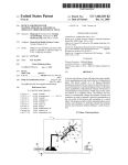
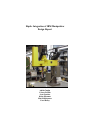
Haptic Integration of IBM Manipulator
Design Report
Adrián Cuadra
Colson Griffith
Scott Gunther
Krista Hirasuna
Matt Kalkbrenner
Carol Reiley
Project Name: Force Feelin’
Project Approvals:
__________________________________________
Project Advisor
_______________________
Date
__________________________________________
Project Advisor
_______________________
Date
__________________________________________
Project Member
_______________________
Date
__________________________________________
Project Member
_______________________
Date
__________________________________________
Project Member
_______________________
Date
__________________________________________
Project Member
_______________________
Date
__________________________________________
Project Member
_______________________
Date
__________________________________________
Project Member
_______________________
Date
1
Table of Contents
1.0 Introduction………………………………………………………………………………..3
1.1 Motivation
1.2 Problem Definition
2.0 Design Process Outline……………………………………………………………………6
2.1 Customer Needs
2.2 Problem Design Specification Summary
2.3 General System Specifications
2.4 Evaluation Criteria
3.0 System Architecture………………………………………………………………………12
3.1System Block Diagram
3.2 System Block Diagram II
3.3Decision Flow Diagram
4.0 Subsystem Designs……………………………………………………………………….16
4.1 Alternatives and Tradeoff Analysis
4.2 Prioritizing Criteria Matrix Analysis
4.3 Concept Scoring Matrix Analysis
5.0 Project Management……………………………………………………………………..18
5.1 Risk Management
5.2 Team Organization
5.3 Policies for Team meetings, communication, documentation, continuity
Technical Appendix
Appendix A: Project Design Specification
Appendix B: Test Plan
Appendix C: Prioritizing Criteria Matrices
Appendix D: Concept Scoring Matrices
Appendix E: Sensor Design Alternatives
Appendix F: Master Controller and Gripper Design Alternatives
Appendix G: User Manual
Management Appendix
Appendix H: Budget
Appendix I: Preliminary Timeline
Appendix J: Fall Quarter Schedule
Appendix K: Status Report Template
Appendix L: Meeting Minutes
Bibliography
2
1.0 INTRODUCTION
Haptics is the use of motor behaviors in combination with touch to identify objects. The study of
haptics emerged from advances in virtual reality. For this design project we are using a human
computer interface that will require a user at one end (master side) and a robot on the other (slave
side). To interact with an environment, there must be feedback. Allowing an operator to feel the
object that is being picked up is an added advantage when controlling a robot. The sense of
touch can be given to the operator through haptic feedback. For example, the user should be able
to feel the sponginess of a sponge while picking it up with a robotic hand.
The team, comprised of one computer, two electrical, and three mechanical engineers, will work
with an existing IBM robotic arm, model 7545, to integrate a haptic system that will provide
force feedback to the operator. The robotic arm was built in 1984, and is in less than mint
condition. It will be necessary to perform needed maintenance before integrating haptic control
into the robotic arm.
3
1.1 Motivation
Having the ability to “feel” what a robotic arm is picking up is a tremendous advantage to many
aspects of our society. The operator can handle fragile and/or dangerous items, without
damaging them or their surroundings. For example, a robot can safely work in areas with
hazardous material without wearing extensive protection where humans cannot. With robots like
ours, the operator can direct the robotic arm to lift and move delicate glass flasks in a radioactive
environment while being safely situated in a hazard-free area.
Another advantage of a robotic arm with haptic integration is that there are no limitations to its
size. Depending on its application, the robotic arm can be built either bigger or smaller than the
human arm controlling it. For instance, if the robotic arm is scaled up, the robotic arm can lift
objects too heavy or too large for humans to lift. Construction site operators, for example, can
have more control over what and to where they are lifting. Anything from glass tests tubes to
iron crowbars of all shapes and sizes can be moved with no difficulty.
Robotic arms with haptic integration are not only limited to lifting objects. They can also be
very beneficial in the medical world. Robotic arms can perform numerous surgeries at once with
the control and direction of only one doctor. In addition, if the robotic arm is scaled down, it
could have much more control and precision than the human hand. The robotic arm could
perform minimally invasive surgery, and be able to cut thin veins and arteries and compress
delicate tweezers without difficulty.
With these ideas in mind, we decided to be the first senior design team at Santa Clara University
to integrate haptic technology with a robot, helping make tasks more realistic for robotic
operators.
4
1.2 Problem Definition
Add haptic force feedback to the existing IBM 7545 industrial manipulator in order to integrate a
sense of feeling while transporting objects to a desired position. The robotic arm intended for
this project (IBM manipulator) has been out of use for several years. We are unsure of the
capabilities/functions of the robot and the required maintenance needed for it to be functional.
As a result, our first task is to learn to operate the arm using the existing controller and determine
the extent of maintenance required.
Upon completion, we will move to the essence of our project. There are two major
concentrations within the scope of our project. The first is to replace the robotic gripper with our
custom design. This design will include sensors enabling haptic integration throughout the
system. The second major aspect of the project is a fully functional “control station” consisting
of an off-the-shelf joystick for gross movement of the arm (left/right, up/down), and a custom
“grip” interface with force-feedback coming from the robotic gripper, so that the user “feels” an
object as it is being picked up.
If this project is successfully completed ahead of schedule, we would also like to incorporate the
following extra features:
• The addition of one or more video cameras so that the robotic arm can be operated
remotely
• A master-slave manipulator configuration, where the joystick is replaced by an
exoskeleton
• Extra degrees of freedom when controlling the arm, making use of its full capabilities
• Interchangeable grippers for use in different applications
Finally, our project goal is a live demonstration of the robotic arm with and without forcefeedback to show users the benefits of haptic integration.
5
2.0 DESIGN PROCESS OUTLINE
The design process is a well-defined interactive process based on standards and guideline rules.
Iterative design overcomes inherent problems of incomplete requirements. Our project will
follow the Waterfall model:
Requirements
specification
Architectural
design
Detailed design
Implementation
and unit testing
Integration and
Testing
Operation and
Maintenance
Requirements specification: The team tries to capture what the system is expected to provide. It
can be expressed in natural language or in more precise languages, such as a task analysis would
provide.
Architectural Design: A high-level description of how the system will provide the services
required. Describe major components of the system and how they are interrelated. Needs to
satisfy both functional and nonfunctional requirements.
Detailed design: A refinement of architectural components and interrelations to identify modules
to be implemented separately.
6
2.1 Customer Needs and Specifications
Through a process of interviewing and acquiring data from potential customers, insight was
gained regarding customer needs. For the gripper, there is a general desire for the parts to be
manufactured from either aluminum or titanium. Customers prefer use of DC motors, and
recommend a quick closing rate. In addition, the people interviewed expressed a desire for large
lifting capacity of approximately 150 kilograms and a gripper opening of 6 inches. However, the
proposed system for this project will not be used in industrial situations or with heavy objects
and therefore need not be so robust.
When considering the sensors, the people interviewed stressed the importance of using voltage,
force, and position sensors. All three of these sensors have been determined to be necessary for
our haptic application. Using all three will increase the precision of the system and its ability to
pick up fragile objects.
Responses to the questions about the master showed a strong desire for a controller that is easy to
use. It was also evident that the controller needed to be actuated by a DC motor, adjustable to
different situations, comfortable for the user, and compact. Though it would be beneficial to
have a controller with a similar range of control and mobility to that of a human arm, in the
scope of the project, this is not feasible.
On the control methodology, the main response was the need for either a proportional control
law or a proportional, integral, and derivative control law. In assessing the relationship to our
project, it was established that only using proportional control would be easier, but it would
probably be inadequate to get the speed and response needed. Using PID control will allow a
more accurate feedback and response system.
Though the project does not directly relate to building a product based on customer needs, the
process of interviewing and preparing a project design specification were advantageous in
determining some necessary specifications.
7
2.2 Problem Design Specification Summary
In order to identify proper design specifications for the haptic manipulator project, it was
necessary to determine a datum that the specifications could be based on. The datum for the
gripper is DEXTER, a custom design two-fingered robotic hand. The datum for the master is an
instrumented glove with a force feedback exoskeleton. The entire robotic system was owned and
tested by Stanford’s robotics laboratory. The datum for the robotic arm controller is the existing
IBM control box.
There are four major components of the project to implement force feedback with the IBM
robotic arm. The first major component of the project is designing and building a robotic gripper
with a dc motor as the actuator to replace the existing pneumatic robotic gripper. The new
gripper will have one degree of freedom. It will be able to supply 0.5 to 40 lbs of force, and it
will have a contact area of 9 in2 . Other specifications are given in Appendix A. The second
major component is designing and building the human interface controller. The physical
specifications are the same as the gripper because a one to one relationship between the two is
desired in order to increase simplicity. This is sensible because the MASTER will be operated
with the thumb and index and middle fingers, and the objects that the robot will be picking up
are easily picked up by the thumb and index finger. For exact information and values please
refer to Appendix A. The third component of the project is the existing robotic arm. The robotic
arm was previously built and is more than adequate for the task we are trying to complete. The
exact numerical specifications are given in Appendix A. The final component of the project is
the sensing capabilities. The sensors should be able to sense position, speed, and force. The
exact details and specifications are given in Appendix A.
Overall specifications for the project include cost, manufacturing time, maintenance
requirements, shelf storage life, quantity, life span, comfort for operator, safety, learning curve,
aesthetics, installation, and service life. The exact quantities for these specifications can be
found in Appendix A.
8
2.3 General System Specifications
The project will consist of three major parts: the existing IBM robotic arm, a new gripper with
haptic integration, and a human interface to move and control the robotic arm and gripper.
Existing IBM Robotic Arm:
• Five degrees of freedom
• Multiple motors
• Horizontal and vertical movement of gripper
• Setup to be used with a control interface
• Could fit in a 4’x4’ box
Gripper:
• ~ 3”x3”
• Aluminum
• Pressure sensor pads on gripping surface
• Motor driven design to open and close
• Receptor to attach to robotic arm
• Able to pick up at least two pounds
Master Controller:
• Two controllers (one for gripper and one for arm movement)
• Both mounted in arrangement for easy use
• Gripper controller
• ~2”x2”
• Opening and closing controlled by human
• Motor to give resistance back to the user when something is picked up with the gripper
• Robotic arm controller
• Off-the-shelf joystick for up/down and left/right movement
• 360 degree motion to control horizontal movement of arm
9
2.4 Evaluation Criteria
Upon completion of this project there are several objectives that should be met. The evaluation
criteria will first include confirmation of a working robot. Secondly, the performance of a
substitute control station should be assessed, and finally, testing and analysis of the haptic
technology should be completed. These main objectives should be evaluated based on the
following criteria:
Mechanically:
• IBM robot is equipped with a new motor driven gripper to replace existing pneumatic
gripper
• How well does it integrate with the existing arm/gripper attachment?
• Does the gripper meet functionality standards? (i.e. is it operable for customer use)
• Does the gripper meet realistic performance standards? (i.e. max stress and strain, max
torque)
• Is there proper use of a P, PD, or PID controller?
• Is the unit easily machined?
• Ease of installation
• Overall impression of design
• Control Station
• Does it provide a means of control for various degrees of freedom?
• Is design easy to use?
• Does it provide a mechanical means of giving force feedback to user?
• Overall impression of design
Electronically:
• Gripper
• Do sensors/encoders provide feedback relating to the force applied to the paddles?
• Does the gripper respond to a “harder squeeze” from the input device?
• Can the performance be easily adjusted (i.e. gain levels, speed of motors, response time)
• Control Station
• Do sensors/encoders provide necessary information to be transferred to robotic arm?
• Do the electronics provide a means of receiving information from the robot and sending
the correct response to that input
Programming:
• Overall System
• Successful integration of robot gripper and input device
• Does the software allow for dynamic operation (i.e. several operations at once)?
• Can the programming be easily changed for fine tuning?
• Is there some sort of means of quantifying performance (i.e. A/D values, response
frequency, gripper force)?
• Is code organized and easy to follow?
• Documentation
• Is there enough documentation so a new programmer could understand what was coded?
10
•
Are variables clearly labeled?
General Testing: (for a full test plan please refer to Appendix B).
• Robot arm should pick up “fragile hazardous material” and place in appropriate container
• Should be able to demonstrate the difference in haptic control and the existing normal
control
• What are the maximum and minimum performance characteristics (i.e. max. and min.
gripping force)
• Does the input device provide some sort of “feel” to the user that is similar to the item
being picked up? (i.e. picking up a rock versus a sponge)
• Can the user decide how much force is applied in the gripper? (i.e. can the user safely
pick up an egg and then break it on command)
Project Risks:
• Injuries
• Dropped objects
• Loose wire
• Lack of Planning
• Lack of communication between team members
• Time wasted learning technology instead of using it.
• Unrealistic planning
• Computer not running
• Too expensive
11
3.0 SYSTEM ARCHITECTURE
3.1 System Block Diagram
Controller
Motor
Transmission
Master
Operator
Position
Sensor
Master
Force Sensor
Controller
Motor
Transmission
Position
Sensor
Slave
Force Sensor
12
Slave
Gripper
The system block diagram above shows the connections of all the major subsystems of the
project. The order of events in normal operation is as follows:
1. The system turns on and the arm resets to the Home position. Both the master and
gripper are initially open.
2. The user will move the joystick (position sensor reading) making the robot arm move
accordingly with the help of a controller and motor.
3. The user will move the joystick down (position sensor reading) making the robot arm
descend towards the target object.
4. The user will close the pincher of the master slowly (position sensor reading) making the
robot gripper slowly close accordingly.
5. The robot gripper will encounter an object (force sensor reading) and turn on feedback
motors on the pincher of the master until the force sensed at the master is equal to the
force sensed at the gripper. At this point, the object will be firmly gripped by the robotic
gripper and the user should feel its feedback.
6. To release the object, the user will slowly decrease pressure on the pincher of the master
by opening up (position reading) and the robot gripper will open accordingly while also
decreasing pressure on its sensors.
7. When the gripper pressure is equal to zero, the pincher feedback motors will stop
responding and the pincher will be free to open almost frictionless. The robot gripper
will open accordingly (position reading).
13
3.1.1 System Block Diagram II
User Interface
Input Device
(Joystick)
X
Y
Grip
AdcGrip
Motor
Motor Driver
Serial
Grip
Theta
Adc
Adc/input
RS-232
RS-485
SPI
Z axis
pwm
Feedback
Future
Serial
ADC Grip (FSR)
RS-232
RS-485
ADC Theta (pot)
ADC Z axi (pot)
Feedback
Sensor
Motor Microcontroller
1)Send serial request
2) Receive command
3) Read Input threshold
4) Generate motor command and send
Sensor Microcontroller
1)Read ADC
-Grip
-Wrist
-Elbow
2)Check thresholds (internal)
3)Set output thresholds
4)Send serial data
14
3.3 Decision Flow Diagram
Similar to the Block Diagram operations, the decision flow diagram visually represents the
actions taken by the controller when iterating through the system.
User Input
Push to close
pincher?
NO
YES
Mover gripper to same position as
pincher
Did the pincher
touch object?
NO
YES
Force above
minimum
threshold?
NO
YES
Activate feedback pincher motor
Gripper and
Master Controller
force sensors
YES
15
NO
4.0 SUBSYSTEM DESIGNS
4.1 Alternatives and Tradeoff Analysis
The first step to choosing a design for the individual subsystems (gripper, master controller,
sensors, controllers) was to brainstorm ideas and sketch possible solutions. Once several
legitimate solutions were developed, a very organized process was followed in order to properly
score each design idea. First, all of the design criteria for the subsystems were carefully
prioritized against each other in order to determine which criteria were most beneficial to a good
design. Once all of the specific criteria were prioritized and given an ‘importance’ weight factor,
the subsystem design ideas were scored against each other (better, equal to, or worse than a baseline design). A higher score defined a better design for this project.
4.2 Prioritizing Criteria Matrix Analysis
For a full breakdown of prioritizing criteria matrices, please refer to Appendix C.
Force Sensor Criteria
The most important criteria in the design of our force sensors was accuracy because in order to
achieve good haptic feedback, only the best accuracy ensures a high-quality realization of touch
from the robot gripper to the human user.
The least important criterion was cost. Even though cost is usually a driving factor in most
projects, the type of sensors we looked at were well within the allocated budget for the project.
Master Controller and Gripper Criteria
The most important criterion in the design of the human interface controller and gripper was
deemed to be the ease of controllability followed closely by accuracy. Since the goal of the
project is to control the robot arm and gripper as well as possible while maintaining high-quality
feedback, controllability and accuracy make the most sense.
Once again, the least important criterion was cost for the same reasons as above.
Controller Criteria
The most important criterions were regarding programming space and capability. For the
project, the amount of programming space and the range of use the controller can handle was
critical to our success.
4.3 Concept Scoring Matrix Analysis
For a full breakdown of concept scoring matrices, please refer to Appendix D.
Force Sensor Design Alternatives
16
The highest-ranked force sensor implementation was the “gas-pressure sensor” followed closely
by the Force Sensing Resistors (FSR) and strain gauge. The gas-pressure sensors were the
highest scored design, but not the best match for our project. They would be very hard to
implement due to its many pressurized gas chambers and tubes. The preciseness needed to build
these sensors is far beyond our scope and therefore we would yield a lower accuracy than
possible—rendering this design much worse than scored by the matrix. Therefore, although no
concrete choice has been made so far in the sensor trade-off, the FSR seems to be the best option
because of its ease of installation, circuit design implementation, and practicality.
For a full description of alternatives, please refer to Appendix E.
Master Controller and Gripper Design Alternatives
A screw driven gripper was actually the highest scored design because of its linear paddle
movement and its ability to convert motor torque to high gripper force, but the design could not
be used for the master because of the threaded screw. It was found that a simple design using a
DC motor with a spur gear and rack could be used to drive a sliding platform. This general
design was chosen because it ranked highly for both gripper and master controller design tradeoff analysis. Though it did not score as highly as some screw driven grippers, its universality for
both uses will ease the manufacturing process and eliminate any proportionality issues that may
occur when controlling two different designs.
For a full description of alternatives, please refer to Appendix F.
Controller Design Alternatives
The highest ranked controller was the AVR microcontroller since it has sufficient programming
space based on the model chosen. Our decision to choose the Atmel 16 was based on
programming size and capabilities as well as the RSL’s long standing use of this brand of
microcontroller. All microcontrollers have a RISC core running single cycle instructions and an
I/O structure that limits the need for external components. AVR instructions are tuned to
decrease the size of the program whether the code is written in C or Assembly. With on chip in
system programmable Flash and EEPROM, this controller is the perfect choice.
For a full description of alternatives, please refer to Appendix G.
17
5.0
5.1 Risk Management
Risk management will be done through a qualitative approach. This section of the project plan
lists some risks that were identified by the project planning team. This list represents the risks
perceived before the project has begun executing. Risk management must be an on-going task
because new risks will emerge over the course of the project. The emerging risks must identified
and managed; otherwise the risks can cause the project to fail. Every project must involve some
uncertainty and risk because it is impossible to anticipate and plan for every risk.
The four steps in risk management are Identification, Assessment, Mitigation, and Monitoring.
Risk
Identification
Checklist
Risk Monitoring
Brainstorming
Meeting
Risk Team
Weekly selfevaluation
18
Risk Assessment
Brainstorming
meeting
Risk Mitigation
Risk Identification
Risk identification involves a brainstorming session by our senior design team. Before the
brainstorming meeting, the team members individually brainstorm and write down the risks to
the project. At the brainstorming meeting, the risks are discusses and tabulated into a single list
of risks. The table below lists the risks identified by the project planning team
Description
Product feature poor
Conflicting assignments
Inexperienced project members
Project objectives are unclear
Estimates are not validated
Ordered parts come late
Risk Mitigation
The risk mitigation plan details the actions that should be taken to reduce the project risk. There
are four ways to reduce risk: Transfer, Mitigate, Contingency Plan, and Accept. Risk Transfer is
used when we are willing to share the risk. Risk Mitigation is the most common tactic to deal
with risk. This tactic attempts to reduce the probability or impact of a risk by applying
management methodologies, business tactics, or additional resources. A contingency plan
provides a safety net to reduce the risk. Risk acceptance is the least desirable risk plan and as
such, should only be used on the lowest cost risks to the project. Risk acceptance is used when
the cost of mitigation exceeds the cost impact of the risk.
5.2 Team Organization
Adrián Cuadra
Colson Griffith
Scott Gunther
Krista Hirasuna
Matt Kalkbrenner
Carol Reiley
EE
ME
ME
EE
ME
CE
High Performance Project team
Effective/High performance project team
A goal of every project leader is to build an effective project team. The outcome of a project
relies on the quality of the team. An effective project team is one that functions as a whole.
Everyone devotes a lot of time to the project. Everyone values the system and the purpose of the
project. Everyone is clear about the priorities of the project. To sum those statements up, an
effective project team is one that collaborates, commits, knows their goals, and is accountable.
19
Collaboration and interdependency consists of a group’s ability to work together as a cohesive
unit. Communication is a very important aspect of collaboration because without it, the team
becomes a group of individual performers. When a group fails to communicate, conflicts arise.
Commitment to the team and the project is another essential element to the successfulness of a
project team. Team members need to commit publicly to the team and the project. Without
commitment, performance can suffer, and the overall effectiveness of using a team rather than a
group of individuals is reduced.
The goals of the team are the clarification of the team’s purpose and the roles of each member.
Without a unifying purpose, member may not understand the objective of the project, they may
not have a clear sense of the team identity, or they may lack a commitment to the purpose.
Accountability is making sure the team purpose, goals, and plan reflect the link back to the
organizational vision, mission, and strategic goals. A certain level of risk and joint action is
needed among all the team members, as well as a mutual accountability, which defines the team
members’ identity and relation to the team project.
Unfortunately team building is an essential aspect that is often overlooked as being unnecessary
or unimportant when working on a project. Most projects have a much better chance at being
successful if some teamwork ground rules are established and some team building exercises are
employed.
20
5.3 Policies for Team meetings, communication, documentation, continuity
Team meetings
For the loose structure of senior design class, finding and arranging meeting times several times
a week was dealt with in an organized manner. Each member would create and give a weekly
schedule plan of their tentative times of availability for the week to the project manager. The
project manager then constructed a master schedule incorporating everyone’s free and taken
times. Based on the master schedule, the team would coordinate and agree on the meeting times
for the quarter. Scheduled times vary quarter to quarter based on member and advisor schedules.
Appendix S shows the available times for F’03.
Team Communication Building
There are several important aspects that need to be practiced for successful communication.
First and foremost in communication is listening. Without listening and understanding what the
other party is saying, there is no communication. Some of the skills of listening include asking
questions, showing interest, and not interrupting.
Constructive feedback is another important aspect in successful communication. Constructive
feedback is the perception, feeling, or reaction to something that is said. Every team member has
to be able to take constructive feedback and give constructive feedback. The key aspect to
remember about constructive feedback is that “you are an expert on other people’s behavior and
your own feelings, you are not an expert on your own behavior and other people’s feelings.”
Documentation
Documentation is extremely crucial for members of the team, advisors, and future collaborators
of this project. It helps organize the goals and breakdown the project into visibly defined
portions that completed. It also helps outsiders and key sponsors comprehend the project and the
work that went into it. Each team member is expected to thoroughly document the work they did
and problems they encountered. Documentation is not only for the work the finished, but also
for work in progress. If is important to clearly document what each member is contributing and
what they plan to do. This will help each member of the team have a thorough understanding of
what needs to be done. View Appendix L for the weekly status report template for the team
members to record.
After each meeting with the advisor, outlines of the notes taken during the meeting also need to
be typed up and placed in a readily accessible location for all members to view. View Appendix
M for Meeting Minutes.
Goals and Accountability
Ensuring every member of the project team is aware of the project goals and their individual
goals is vital to the success of the project. Having a fixed project goal prevents hidden agendas
from taking priority, emphasizes that the entire team shares responsibility for achieving the goal
21
and eliminates any uncertainty that team members may have in their role toward making the
project succeed.
To accomplish this, the project manager should begin each meeting by succinctly stating the
goal. By the end of the meeting, team members should leave the meeting knowing exactly what
their action items are before the next meeting. In addition, the project manager should meet with
his/her team on an individual basis at least once a week to ensure that things are running
smoothly. If the team member has any issues, the project manager should address the issues
during the meeting.
22
TECHNICAL APPENDIX
23
Appendix A: Project Design Specification
Group Name: Force Feelin'
Date: 11/19/2003
Product Definition: Haptic Controlled Robotic Arm
Revision: 2
Parameters
Elements/Requirements
units
Datum
Incremental
Best
Performance:
Gripper
2
Pallet size
in
1
9
16
Maximum force
lbs
80
40
80
Minimum force
lbs
1
0.5
0.1
Closure time
sec
6
4
2
Response time
sec
0.25
0.1
0.05
Degrees of freedom
#
2
1
2
Maximum payload
lbs
5
1
2
Weight
lbs
2
3
2
in
0.0005
0.001
0.0001
sec
0.05
0.1
0.05
Human Interface Controller
Accuracy
Response time
2
Pallet size
in
2
4
6
Maximum force
lbs
40
60
80
Minimum force
lbs
1
1
0.1
Closure time
sec
2
4
2
#
2
1
2
lbs
2
3
2
deg
200
180
200
#
4
2
4
deg
0.5
1
0.5
Degrees of freedom
Weight
Robotic Arm
Range of motion
Degrees of freedom
Theta increment
24
Position repeatability
in
0.005
0.002
0.001
Voltage
volts
220
24
24
Current
amps
13
20
20
Speed
in/sec
57
43
57
Tmasterkness
in
0.25
0.1
0.05
Surface area
in
5
10
16
Repeatability
%
99
95
100
msec
5
3
1
$
4000
2500
1500
months
24
7
6
Maintenance
time
weekly
weekly
monthly
Shelf life storage
time
6 months
1 year
5 years
Quantity
units
1
1
1
Product life span
cycles
1000
5000
10000
Comfort
rating
really good
good
really good
Safety
rating
really good
good
really good
min
120
30
10
Aesthetics
rating
really nice
nice
really nice
Installation
hrs
3
2
1
years
5
10
20
Sensors
Response time
Product cost
Time scale
Learning curve
Life in service
2
25
Appendix B: Test Plan
1.
Press the ‘RETURN HOME’ pushbutton on the microcontroller, and verify that the
Z-axis retracts to its fully upright position and the arm rotates to its fully CW position
2.
Using the user interface keyboard
a. Type in 180 degrees for the Theta1 angle and verify that the arm moves to this
position
b. Type in 0 degrees for the Theta1 angle and verify that the arm moves to this
position
c. Type in 20 degrees for the Theta1 angle and verify that the arm moves only 20
degrees
d. Type in 1 degree for the Theta1 angle and verify that the arm moves only 1
degrees
e. Type in the maximum z-axis position and verify that the arm moves to this
position
f. Type in the minimum z-axis position and verify that the arm moves to this
position
g. Type in 0.1 m and verify that the arm only moves up 0.1 m
h. Place a block on a table and verify that the manipulator can move and position its
gripper around the object
i. Type in invalid values (negative numbers, ASCII values, symbols) to make sure
that a correct error message displays
j. Leave value blank and see if it defaults to zero
k. Type values that exceed the max and min
3.
Using the user interface joystick
a. Push the joystick to the right and verify that the arm rotates a complete 360
degrees clockwise
b. Push the joystick to the left and verify that the arm rotates a complete 360 degrees
counterclockwise
c. Push the joystick upward and verify that the arm moves to the maximum z-axis
position
d. Push the joystick downward and verify that the arm returns to its minimum z-axis
position
e. Move the joystick to the right for 0.5 second, and verify that the arm stops when
the joystick returns to the center
f. Move the joystick up for 0.5 second, and verify that the arm stops when the
joystick returns to the center
g. Place a block on a table and verify that the manipulator can move and position its
gripper around the object
h. Move the joystick quickly right then left to see what the response time is. Does it
stall the machine, have a delay, or do the motions cancel each other out
4.
Using the pincher, with the force feedback not connected
26
a. Close the paddles to its maximum displacement, and verify that the gripper is
maximally closed
b. Let go of the paddles and verify that the pincher opens to its full extent, and that
the gripper also opens to its full extent
c. Move the paddle 1cm and verify that the gripper moves 1cm
5.
Using the pincher, with force feedback connected
a. Place a solid block between the paddles of the gripper
b. Displace the pincher until the gripper touches the block, and verify that the
pincher’s paddle stops moving
c. Press the paddles harder together and verify that the force feedback motors are
exerting more torque
d. Place a Styrofoam cup between the paddles of the gripper
e. Displace the pincher until the gripper touches the cup, and verify that the pincher
feels some resistance
f. Press the paddles of the pincher harder together and verify that paddles move
inward and also feel resistance
g. Displace the pincher’s paddles enough to break the cup, and verify that there is no
longer any resistance
27
Appendix C: Prioritizing Criteria Matrices
PRIORITIZING MATRIX
Force Sensors
CRITERIA
1
1 Linearity
2
3
4
5
6
7
0.5
0
1
0.5
0.5
TOTAL
FACTOR
0.5
3
3
0.5
1
0.5
0.5
1
4
5
1
0.5
0.5
1
4.5
6
0
0
0
0
1
0.5
1
4
5
0.5
3.5
4
2
2
2 General
Complexity
3 Accuracy
0.5
1
0.5
4 Cost
0
0
0
5 Universality
0.5
0.5
0.5
1
6 Practicality
0.5
0.5
0.5
1
0.5
7 Size
0.5
0
0
1
0
8
9
10
11
12
13
(MasterController/
Gripper)
0.5
8
9
10
11
12
13
28
PRIORITIZING MATRIX
Gripper and Master Controller
CRITERIA
1
1 Linearity
2
3
4
5
6
7
8
9
10
1
0.5
0.5
1
0.5
1
1
0
TOTAL
FACTOR
0.5
6
4
0
0
1
0
1
1
0
0.5
3.5
3
1
1
0
1
1
0
1
6.5
5
1
0
1
1
0
0.5
5
3
0
1
0.5
0
0
1.5
2
1
1
0
1
7.5
5
0
0
0
0
1
0
0
1.5
2
1
9
5
5.5
4
2 Manufacturability
0
3 General
Complexity
4 Torque to Force
0.5
1
0.5
1
0
5 Speed
0
0
0
0
6 Accuracy
0.5
1
1
1
1
Cost
0
0
0
0
0
0
8 Frictional
Aspects
9 Controllability
0
0
0
0
0.5
0
1
1
1
1
1
1
1
1
1
10 Universality
(MasterController/
Gripper)
0.5
.5
0
0.5
1
0
1
1
29
1
11
12
PRIORITIZING MATRIX
Controller
CRITERIA
1
1 Capability
2
3
4
5
0.5
1
1
1
2 Complexity
0.5
3 Speed
0.5
0
4 Cost
0
0
0
5 Programming
Space
1
1
1
6
7
8
TOTAL
FACTOR
0
2.5
3
1
0
2.5
3
1
0
1.5
2
0
0
1
4
4
1
30
9
10
11
12
Appendix D: Concept Scoring Matrices
CONCEPT SCORING MATRIX
Force Sensors
Baseline = Force Sensing Resistor
DESIGN IDEAS
CRITERIA
FACTOR
1. FSR 2. Strain
Gauge
5. piezo 6. flex
7. A/V
material resistor reading
3
3. gas
4. touch
pressure screen
sensor
1 3
.5 1.5
Linearity
3
.5 1.5 1
.5 1.5
.5 1.5
0
0
Complexity
5
.5 2.5 0
0
.5 2.5 0
0
0 0
.5 2.5
1
5
Accuracy
6
.5 3
1
6
1
6
0
0
0 0
0
0
0
0
Cost
1
.5 .5
0
0
0
0
0
0
1 1
.5 .5
1
1
Universality
5
.5 2.5 .5
2.5
.5 2.5 .5
2.5
.5 2.5
0
0
.5 2.5
Practicality
4
.5 2
0
0
0
0
0
0
.5 2
0
0
0
0
Size
2
.5 1
0
0
0
0
.5
1
.5 1
.5 1
1
1
TOTAL
13
11.5
14
5
8
5.5
9.5
RANKING
2
3
1
7
5
6
4
1
CONCEPT SCORING MATRIX
Gripper
Baseline =
Idea #1_
DESIGN IDEAS
CRITERIA
FACTOR 1.
2.
3.
4.
5.
6.
7.
8.
9.
10.
11.
12.
Linearity
4
.5
2
1
4
1
4
1
4
1
4
1
4
1
4
.5
2
1
4
1
4
1
4
1
4
Manufacturability
3
.5
1.5 0
0
0
0
0
0
0
0
.5
1.5
0
0
0
0
.5
1.5 1
3
.5
1.5 1
3
General
Complexity
Torque to Force
5
.5
2.5 0
0
.5
2.5 0
0
0
0
.5
2.5
0
0
0
0
.5
2.5 .5
2.5
.5
2.5 1
5
3
.5
1.5 1
3
.5
1.5 .5
1.5 1
3
1
3
.5
1.5
.5
1.5
1
3
1
3
0
0
1
3
Speed
2
.5
1
0
0
.5
1
.5
1
.5
1
.5
1
1
0
0
0
0
0
0
0
1
2
0
0
Accuracy
5
.5
2.5 1
5
1
5
1
5
1
5
1
5
1
2.5
.5
2.5
1
5
1
5
.5
2.5 1
5
Cost
1
.5
.5
0
0
.5
.5
0
0
0
0
.5
.5
0
0
0
0
.5
.5
.5
.5
.5
.5
.5
.5
Frictional Aspects
2
.5
1
0
0
1
2
1
2
1
2
1
2
0
0
0
0
0
0
1
2
.5
1
1
2
Controllability
5
.5
2.5 1
5
1
5
1
5
1
5
1
5
1
2.5
.5
2.5
1
5
1
5
1
5
1
5
Universality
4
.5
2
0
.5
2
.5
2
.5
2
.5
2
0
0
0
0
0
0
0
0
0
0
0
0
0
TOTAL
17
17
23.5
20.5
22
26.5
17.5
7.5
21.5
25
19
27.5
RANKING
9
9
4
7
5
2
8
12
6
3
7
1
2
CONCEPT SCORING MATRIX
Pincher
Baseline = Idea #1
DESIGN IDEAS
CRITERIA
FACTOR 1.
2.
Linearity
4
.5
2
1
4
1
4
1
4
1
4
1
4
1
4
.5
2
1
4
Manufacturability
3
.5
1.5 0
0
0
0
0
0
0
0
0
0
0
0
0
0
0
0
General Complexity
5
.5
2.5 0
0
0
0
0
0
0
0
0
0
0
0
0
0
0
0
Torque to Force
3
.5
1.5 0
0
1
3
1
3
1
3
1
3
1
3
1
3
0
0
Speed
2
.5
1
0
0
.5 1
.5
1
.5
1
.5
1
.5
1
0
0
0
0
Accuracy
5
.5
2.5 1
5
1
5
1
5
1
5
1
5
1
5
.5
2.5 0
0
Cost
1
.5
.5
0
0
0
0
0
0
0
0
0
0
0
0
0
0
0
Controllability
5
.5
2.5 .5
2.5
1
5
1
5
1
5
1
5
1
5
.5
2.5 0
0
Universality
4
.5
2
0
0
1
4
1
4
1
4
1
4
1
4
1
4
0
0
Practicality
4
.5
2
.5
2
.5 2
.5
2
.5
2
.5
2
.5
2
0
0
0
0
Frictional Aspects
2
.5
1
0
0
0
0
0
0
0
0
0
0
0
0
0
1
2
0
3.
4.
0
5.
6.
7.
8.
9.
10.
TOTAL
19
13.5
24
24
24
24
20
14
6
RANKING
6
8
1
1
1
1
5
7
9
3
CONCEPT SCORING MATRIX
Controller
Baseline = Basic Stamp
DESIGN IDEAS
CRITERIA
FACTOR
1. Basic Stamp
2. PIC
3. AVR Boards
Capability
3
.5
1.5
.5
1.5
1
3
Complexity
3
.5
1.5
0
0
0
0
Cost
1
.5
.5
1
1
.5
.5
Speed
2
.5
1
1
2
1
2
Programming
Space
4
.5
2
1
4
1
4
TOTAL
6.5
8.5
9.5
RANKING
3
2
1
4
Appendix E: Force Sensor Design Alternatives
GENERIC FORCE SENSOR
DIAGRAM
FORCE INPUT
FORCE
SENSOR
5
PROPORTIONAL
OUTPUT DUE TO
APPLIED FORCE
FORCE SENSITIVE RESISTOR
(FSR)
FORCE
INPUT
•
•
•
•
PHYSICAL
SENSOR
(FSR)
ELECTRONIC
CONVERSION
CIRCUITRY
PLUS
Simple (easy to install)
Reasonably accurate
Cheap
•
•
•
•
6
VOLTAGE
PROPORTIONAL
TO FORCE
MINUS
Non-linear
Limited to size and shape
Pressure determined by
area (need small FSR for
good accuracy)
STRAIN GAUGE
GEOMETRIC
EQUATIONS
(FOR
POSITION)
FORCE
INPUT
•
•
•
•
ELECTRONIC
CONVERSION
CIRCUITRY
PHYSICAL
STRAIN GAUGE
PLUS
Best accuracy
Linear
Gives force and direction
•
•
•
•
7
VOLTAGE
PROPORTIONAL
TO FORCE
MINUS
Very expensive
Takes up gripper space
Difficult to impement
GAS PRESSURE SENSOR
GAS
PRESSURE
SENSOR
FORCE
INPUT
•
•
•
•
•
•
ELECTRONIC
CONVERSION
CIRCUITRY
COMPRESSIBLE
AIR RESERVOIR
PLUS
Mechanically easy to implement
Cheap
Sensor not on gripper itself
Linear
Custom shape and size of
reservoir
•
•
•
8
VOLTAGE
PROPORTIONAL
TO FORCE
MINUS
Inaccuracy of transmission line
No force applied location
information given
TOUCH SCREEN
X AND Y
COORDINATES
FORCE
INPUT
•
•
TOUCH
SCREEN
MATRIX
PLUS
Gives exact locations for
computer mapping of pressure
applied
MICROCONTROLLER
•
•
•
•
•
9
VOLTAGE
PROPORTIONAL
TO FORCE
MINUS
Expensive
No true force reading
(force per area only)
Hogs CPU time
Takes up space in gripper
PIEZZO-ELECTRIC MATERIAL
• PLUS
• Cheap
• Custom size and
shape
•
•
•
•
MINUS
Difficult to build
Many inaccuracies
Only measures
δC
changes in
capacitance
δt
10
Appendix F: MASTER and Gripper Design Alternatives
1
Gear Driven Sled
This design is universal for both the gripper and the pincher. One of the pallets is fixed at the
end of the stationary platform. A motor drives a moving sled assembly and a gear assembly
slides on a grooved track on the stationary platform. As the motor is turned the gears grab
causing the moving portion to slide the two paddles open or closed. The system would be able to
go to an open home position by driving the motors when an input from the user is not present.
2
Cable Driven Sled
This design is universal for both the gripper and the pincher. One of the pallets is fixed at the
end of the stationary platform. A moving sled assembly is driven by a motor and cable wrapped
around the shaft. As the motor is turned, the cable that is fixed to the moving sled causes the
sled to follow the track. The system would be able to go to an open home position by driving the
motors when an input from the user is not present. Very similar to controls lab setup.
Dual Cable Driven Sled
In this design there is a sold piece with a track machined into it. Two sleds with the paddles
attached are driven by cables each connected to a motor. The motors pull each sled towards the
middle of the unit, and a spring setup allows the system to return to a home or open position.
3
Motorized Scissors
A stationary paddle attached to the robot remains in place as a moving paddle rotates at a pivot
point. The moving paddle has an extended piece that creates a moment arm and a surface for the
motor and gears to interact. A DC motor is used to open and close the scissor setup and when a
force is not applied the system can be programmed for the motor to return to the open position.
4
5
6
7
Appendix G:
Below is the pluses/minus of each of the three controllers analyzed.
– Paralax basic stamp
– Microchip Pic Microcontroller
– Atmel's AVR microcontrollers
BASIC STAMP
PLUS
Easy to learn
Multithreaded
Expandable
Great documentation and support
MINUS
Relatively slower
Limited
Can not handle buffers
More expensive ($60-70)
PIC MICROCONTROLLER
PLUS
20MHz
4 CPI
Price ($5-10)
ADC included
Flexible
MINUS
10W programming space
*8KB PROM
Memory Page (4 sections)
Also limited capabilities
Have to pay for compiler
*Buggy
ATMEL MICROCONTROLLER
PLUS
Price $12-$16
Free compilers
Support libraries
MINUS
Harder to use (not as documented)
Written in C (harder to pass project)
Besides the Atmel 8 bit RISC Models Analyzed, we also explored options such as system on a
chip, personal computer, and single board computer.
Qualities to look for if you plan to use PC as brains in a no tethered robot.
– Small size
– Standard power supply requirements
– Accessibility to microprocessor system bus or an input/output port
– Uni/bidirectional parallel port
– Programmability
– Mass storage capability
– Availability of technical details
1. System on a chip
- Flexible
- High capabilities
- New to the lab
- No advanced or experienced users
- Hard to learn
8
-
Uncertain when we will receive them
2. Personal computer
- Examples include an IBM PC compatible or an Apple Mac
3. Single-Board computer
- Programmed in high level language or assembly.
- Offer more processing power than microcontroller.
4. Microcontroller
- Inexpensive and have simple power requirements (usually +5V)
- Infield programming and reprogramming
9
Appendix H: User Manual
System Overview
• Manipulator
The manipulator is a two-jointed arm structure with two degrees of freedom in use.
The joint of the arm, called the Theta-1 axis, provides 1 degree of freedom through its
swivel motion. The end-of-arm provides the second degree of freedom through a
vertical shaft called the Z-axis.
•
Controller
The controller contains most of the electronics for control of the manipulator
operation. A microcontroller coordinates the manipulator’s movement and monitors
its speed and positioning.
•
Control Station
o The control station consists of either a keyboard or joystick to move the
manipulator and a master gripper that controls the pressure and displacement of
the slave gripper.
1. Connecting the Robot for Operation
a. Roll the robot into the center of the floor so that the extended arm cannot hit
anything. The “circle of safety” should have a radius of at least 4 feet around the
base of the robot. Note that the robot can reach beyond the platform, and can be
dangerous. The “circle of safety” must be clearly identified whenever power is
applied to the robot or controller.
b. Verify that the control box is connected to the robot.
c. Connect the controller power cord to a 220 VAC, 30A, single-phrase (NEMA L630S) wall outlet. This is a twist-lock connection, so push the plug in firmly and
twist it clockwise to lock it.
2. Powering on the Manipulator
a. Verify that the arm’s z-axis position is not overextended. The arm must be in a
position within the workspace and not at its maximum height.
b. Insuring first that the “circle of safety” is clear, turn on the power switch to the
controller.
c. Check the control panel. The POWER and LED should be lit.
3. Home the Manipulator
Press the RETURN HOME pushbutton on the microcontroller. The LED will turn on
and stay on. The Z-axis will retract to its fully upright position and the arm will
rotate to its fully CW position. When this happens, the robot is HOME.
10
Upon completion of the Homing sequence, all axes will stop movement and the
HOME LED will turn off.
4. Operating the Control Station
a. Moving the manipulator to a desired position using the keyboard
i. Type in the theta-1 value in degrees and press ‘Enter’
(Note: 0 degree is located at the red mark on the platform and each
subsequent degree is measured clockwise from this mark)
ii. Type in the z-axis value in meters and press ‘Enter’
iii. The robot should now be in its desired position.
b. Moving the manipulator to a desired position using a joystick
i. Move the joystick to the left in order to rotate the arm. counterclockwise
and right to rotate the arm clockwise. Return the joystick to its default
upright position to stop movement
ii. In order control the z-axis, move the joystick forward to extend the robot
upwards and back to retract the robot downwards. Return the joystick to
its default upright position to stop movement.
iii. The robot should now be in its desired position.
c. Using the Human Interface Controller to move the Gripper
i. Position the manipulator so that the object is between the gripper’s
paddles and is touching the stationary paddle, or outermost paddle.
ii. Use one hand to displace the paddles of the human interface controller.
iii. Once the gripper “feels” the object, the human interface controller should
also “feel” feedback.
iv. Press the paddles of the human interface controller more tightly together if
a stronger grip is necessary.
v. Once the appropriate force is applied to the object, the object can be
moved with the joystick or keyboard.
vi. In order to release the object, release the paddles of the human interface
controller, so that no pressure or displacement is applied to the controller.
5. Preventive Maintenance
Preventive maintenance should be performed according to the chart in the figure
below
Unit
Manipulator
Z-Screw Thread
Action
Clean
Check Oil Level
Lubricate
Interval
Daily
Daily
Monthly
Z-Shaft
Lubricate
Every 3 months
11
Lubricant
Ball Bearing
Grease (PN
6023725)
Molybdenum
Disulfide Grease
Z-Guidebars
Lubricate
Every 3 months
Theta 1 Axes
Change Oil
Every 6 months
Motor Brushes
Bearings
Check Wear
Pack Bearings
Every 12 months
Every
Replacement
(PN 357830)
Molybdenum
Disulfide Grease
(PN 357830)
IBM No. 10 (PN
1280444) oil or
equivalent (must
have a viscosity
randing of JIS
class 2, number 2)
IBM No. 23
Grease or
equivalent (PN
1280442)
Preventive maintenance may need to be performed more often under dirty and dusty
conditions or during periods of extended use.
6. Safety Notices
o Ensure compliance to all local and national safety codes for the installation and
operation of the system.
o Observe power and grounding instructions.
o The system must not be installed in an explosive atmosphere.
o Observe safe access routes to and from the system.
o Consider installing intrusion devices or safety mats around the manipulator to
drop power if the work area is penetrated.
o Utilize signs around the system when servicing it to alert others to potential
hazards.
o Consider installing additional emergency-off switches for feeders and other
fixtures.
o Stay out of the manipulator work area when power is on. The manipulator arm
moves rapidly with a low of force.
o Always wear safety glasses around the manipulator.
o Remove watches and jewelry when servicing the system.
o Use the STOP button to stop manipulator in emergencies.
o Always check the work area for adequate clearance before applying. power. Be
sure no one is in the manipulator work area.
o Fire extinguishers must be located within easy access.
12
MANAGEMENT APPENDIX
13
Appendix I: Budget
Design Budget
Group Name: Force Feelin'
Supplies
Date: 11/19/2003
Cost
Money Spent
Aluminum
$50.00
$0.00
Nuts, bolts, fasteners
$50.00
$0.00
Replace θ2 motor
Oil, Miscellaneous parts
$400.00
$600.00
$0.00
$0.00
Materials:
Hardware:
Repair Arm:
Electronics:
Gripper Motor
Motor Drivers
Sensors
Pinch Control Motor
Motor Controller
Micro Controllers
$30.00
$200.00
$250.00
$30.00
$300.00
$150.00
$2,210.00
Total Cost
14
$0.00
$0.00
$150.00
$0.00
$0.00
$0.00
$150.00
Appendix J: Preliminary Timeline
Group Name: Force Feelin'
Fall Quarter
Week 5
Week 6
Week 7
Week 8
Week 9
Week 10
Finals
Winter Quarter
Week 2
Week 4
Date 10/21/03
22-Oct Problem Definition
Learn how to operate robot
Finish sub-system specs
Finish grant proposals
PDS report
Preliminary Timeline
Budget
Research on mechanical systems
Decide and schedule interviews
Decide on wmasterh robot to use
Finish Don Wilkens tutorial
Preliminary procurement list
Three design ideas per person
5-NovCustomer Needs/Information Gathering
Meet with Pascal
Formulate trade-off table
10-NovFunctional Analysis
10-NovDesign Ideas, Selection Matrices
Organize design ideas
Decide on design (end of week)
19-NovConceptual Design Report
Begin drawings
Design review with Dave Weldon
Begin analysis
3-Dec Design Notebook
3-Dec Analysis Report
Finalize FEA model and hand calculations
10-Dec Layout
10-Dec Mockup
Prepare presentation
12-Dec Design Proposal
Obtain all necessary materials
Detailed drawings
Machining in progress
Revised design review
15
Week 5
Week 6
Week 9
Detailed drawings completed
Assembly drawings completed
Purchase initial hardware
Continue machining
Begin preliminary tests of sub-systems
Machining and assembly completed
Spring Quarter
Week 2
Week 4
Week 5
Begin testing of entire system
Continue testing
Finalize testing
Week 7
16
Appendix K: Fall Quarter Schedule
Schedule
TIME
Monday
Tuesday
Wednesday
8:00 AM
8:15 AM
8:30 AM
8:45 AM
9:00 AM
9:15 AM
9:30 AM
9:45 AM
10:00 AM
10:15 AM
10:30 AM
10:45 AM
11:00 AM
11:15 AM
11:30 AM
11:45 AM
12:00 PM
12:15 PM
12:30 PM
12:45 PM
1:00 PM
1:15 PM
1:30 PM
1:45 PM
2:00 PM
2:15 PM
2:30 PM
2:45 PM
3:00 PM
3:15 PM
3:30 PM
3:45 PM
4:00 PM
4:15 PM
4:30 PM
4:45 PM
5:00 PM
5:15 PM
5:30 PM
5:45 PM
6:00 PM
6:15 PM
6:30 PM
6:45 PM
KEY
Thursday
Friday
ADRIAN
KRISTA
CAROL
SCOTT
MATT
COLSON
2 BUSY
NAME
Matt Kalkbrenner
408-564-4112
Adrian Cuadra
408-504-7669
Colson Griffith
206-619-7409
Krista Hirasuna
408-315-9228
Scott Gunther
360-951-2882
Carol Reiley
408-718-8249
17
Appendix L: Status Report Template
Weekly Status Report Template
Team Member Weekly Status Report Template
Name:___________________________________
Date:____________________________________
0) Summary
1) Weekly Milestones
Due Date
Task Description
% Complete
2) Weekly Action Item Status Detail
Tasks
Open Date
Close Date
Status
3) Accomplishments this week
4) Blocking Issues
18
% Time
Allocated
Appendix M: Meeting Minutes
Date of Meeting
Name of Recorder:
Starting Time:
Ending Time:
Meeting Attendees: _____________________________________________________________
______________________________________________________________________________
Today’s Meeting Goal:
______________________________________________________________________________
______________________________________________________________________________
______________________________________________________________________________
Current Reality:
______________________________________________________________________________
______________________________________________________________________________
______________________________________________________________________________
AGENDA ITEMS:
Who is responsible?
What was decided
Date for completion
Next Steps (Agenda for next time):
______________________________________________________________________________
______________________________________________________________________________
______________________________________________________________________________
19
Bibliography
“Feedback Strategies for Shared Control in Dexterous Telemanipulation” Westen B. Griffin,
William R. Provancher, and Mark R. Cutkosky
“Preliminary Tests of an Arm-Grounded Haptic Feedback Device in Telemanipulation” Michael
L. Turner, Daniel H. Gomez, Marc R. Tremblay, and Mark R. Cutkosky.
“VisHap: Augmented Reality Combining Haptics and Vision” Guangqi Ye, Jason J. Corso,
Gregory D. Hager, Allison M. Okamura,
“Supporting Presence in Collaborative Environments by Haptic Force Feedback.” Eva-Lotta
Sallnas and Kirsten Rassmus-Frohn and Calle Sjostrom.
“Measurement, Analysis, and Display of Haptic Signals During Surgical Cutting” Stephanie
Greenish, Vincent Hayward, Vanessa Chial, Allison Okamura, and Thomas Steffen.
“Virtual surgery simulation using a collocation-based method of finite spheres” S. De, J. Kim,
MA Srinvasan.
“Design Constraints for Haptic Surgery Simulation” Oliver Astley and Vincent Hayward.
”Virtual Hand Toll with Force Feedback” Ravin Balarishnan, Colin Ware and Tim Smith
“Connecting Haptic Interface with a Robot” Ales Bardorfer and Marko Munih
http://elfo.die.upm.es/~macias/r8sac/main/docs/spc2000/ales-bardorfer-short.pdf
“Improving Reality-Based Models For Vibration Feedback” Allison M. Okamura, Matthew W.
Hage and Mark R. Cutkosky, Jack Tigh Dennerlein
http://www-cdr.stanford.edu/touch/publications/okamura_asme00.pdf
“Haptic Devices “Mimic Technologies Inc.
http://www.hitl.washington.edu/people/tfurness/courses/inde543/READINGS03/BERKLEY/White%20Paper%20-%20Haptic%20Devices.pdf
20