1
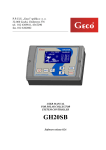
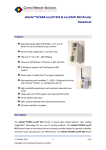
Lmbd3 Combustion Analyzer for oil or gas fired
boilers, furnaces or other units with a closed
combustion chamber and a fan equipped
automatic burner.
LMBD3
The Combustion Analyzer – User's Manual
1. Build
The Combustion Analyzer – User's Manual
2. Before you start using the analyzer
Before you start using the combustion analyzer
Prior to using the device you should thoroughly read this user's manual. In
it you will find tips regarding safe use of the device and it will get you
acquainted with the device's build and functions.
What's in the box
– flue gas combustion analyzer central unit (CPU)
– power supply unit with a cord ( 12VDC= 3A, 100-240VAC, 5060Hz )
– USB cable to connect the device to the computer ( 1,8m )
– CD with software, drivers and a manual
– 18 MM nut made from stainless steel used to install the lambda
probe in the exhaust stack
Unpacking and check
After unpacking you should check whether the device is damaged. If you
have any doubts do not launch the device. In this case you should contact
the seller.
Any materials from the package ( foil, rubber etc.) should be kept away
from children as they may be dangerous to them.
Connecting to mains electricity
Connection to mains electricity must be done accordingly to the
manufacturers guidance and the binding safety regulations.
To do this you should use the power supply provided together with the
device and:
– put the power supply on a non-flammable surface or
– hang the power supply or
The Combustion Analyzer – User's Manual
– put the power supply on a non-flammable dais (e.g. brick)
– put the power supply in a place where it is safe from being
accidentally flooded with water
– do not put the power supply on the floor because any water leak
can flood it
– do not put the power supply too close to heat sources
– mount the power supply away from flammable liquids and gases
prone to ignition and self-ignition
– the guidances above should also be applied to the device itself
The mains electricity socket you are connecting the device to must be
equipped with an appropriate fuse (depending on the circuit) and a
residual current device to ensure the user will not be electrocuted due to
insulation being ruptured, a short circuit, touching, flooding etc. The
electrical installation should be done accordingly to binding safety
regulations.
The manufacturer is not responsible for any damage to third parties or
objects caused by not adhering to the manufacturers guidances.
3. Preparing to launch
The LMBD3 combustion analyzer is designed to be used with any boiler
unit with a closed combustion chamber and a blowtorch where all exhaust
gases are not additionally mixed with air and the whole amount of air
needed for the combustion process is delivered by the blowtorch so we
can analyze their unchanged composition immediately after they are
blown out from the boiler unit.
The combustion analyzer is designed to use an universal lambda probe
that is normally used to analyze the composition of exhaust gases in cars.
You should only use a four-wire, zirconium lambda probe with a built-in
heater. The heaters grounding, signal wire and internal ground potentials
should be physically isolated from the metal case of the probe.
The Combustion Analyzer – User's Manual
You can buy and calibrate the probe on your own, buy a probe with
known parameters or use an additionally bought calibrated probe. The
lambda probe is not an element of the package and you need to buy it
separately.
The durability of the probe depends on the fuel type and the temperature it
is working in. When the fuel that is burned is free of sulfur and other
chemical contaminations then the probe should last anywhere from a year
to a couple of years. However, if we experiment with solid fuels,
varnished woodwork wastes, coal, charred coal, used engine oil or fuel
contaminated with plastic we might damage the probe in just a few days.
4. How to prepare and where to place the lambda probe
For the device to start working you first need to properly prepare the
lambda probe. After being unpacked the probe should be heated. Connect
the probe to the device (the connection scheme is placed on the devices
front panel), then turn on the power supply and leave the probe for around
an hour while it heats up and burns any contaminations.
!!! Connecting the lambda probe to power supply in an improper way
will cause damage to the probe.
!!! Please remember that the probe heats up to temperatures up to
200°C (392°F) and more and touching it when it reaches that
temperature will result in burns. Please be very careful when handling
the lambda probe.
During the heating process, the probe should be placed on a nonflammable, preferably stony or ceramic (brick, tile, concrete) surface in
free air.
The Combustion Analyzer – User's Manual
The lambda probe is very sensitive to falls. Dropping it will result in
permanent damage, the zirconium oxide tube will crack.
After the probe heating process is complete you can connect the device to
a laptop (or any other computer you wish to use the device with) using the
USB cable received in the package. The USB socket is placed next to the
power supply sockets.
The device has two sockets for two different types of plugs.
!!! Connect only one power supply to a fitting socket !!!
After you install the drivers and the device is recognized by the operating
system, run the software (found on the CD) to operate the device. Just
copy the software from the CD to the hard drive and run it (the software
does not require installation).
!!! It is impossible to use the software without installing USB drivers
first !!!
Without proper drivers, every time you try to run the software it will
cause a system error saying some system files are missing. This is normal
and should not cause concern.
You should first connect the device to the computer with an USB cable,
then turn on the power supply, wait for Windows to ask for the drivers and
then install them from the CD. Windows will ask for the drivers twice and
you should pick the folder on the CD where they are stored.
!!! Only after installing the drivers you will be able to run the
software !!!
The Combustion Analyzer – User's Manual
Picking the mounting spot
These pictures show different ways to
mount the probe in your exhaust stack
depending on its shape. Due to their
design, some probes should not be
mounted horizontally as it will cause
drip to accumulate. Probes mounted in
improper ways were marked with a red
'X'. The probes should always be
mounted vertically, at an angle
pointing downward or – as a last resort
– horizontally and as close to the
boiler units exhaust as possible. Do not
mount the probe upside down or at an
angle where the cables are pointing
downward.
The Combustion Analyzer – User's Manual
The probe should be protected so that water does not get inside it through
the wires. You cannot seal the spot where the wires enter the probe.
A prepared probe should be mounted in a spot suitable for doing
measurements, that is as close to the boiler units exhaust as possible (as
seen on the pictures above). When possible, the probe should be placed in
the exhaust gases draft where the temperature is the highest, not further
from the exhaust than at a distance of four times the diameter of the
exhaust stack. The closer to the boiler unit and it's exhaust, the better.
A built-in heater makes the lambda probe less sensitive to the distance
from the exhaust and the exhaust gas temperature. However, pick the
mounting spot with care as you want to be sure that the exhaust gases are
hot and make contact with the probe. Sometimes a few attempts of
picking the mounting point are needed before the right one is found.
The durability of the probe will be shortened if the gases are too hot.
The outer part of the probe should be kept clean. Liquids should not be
used to clean the probe as they can leak into the casing through the front
of the probe or the back where the cables are placed. The probe should not
be cleaned using solvents or wire brushes.
!! ATTENTION !!!
After the lambda probe is placed inside the exhaust - pipe it must at all
times be heated by the built-in heater. The device takes care of heating
the probe. If you plan any breaks in using the device (e.g. you plan to
disconnect the power supply from the device) you should remove the
lambda probe from the exhaust pipe. Otherwise it will soon become
damaged or degraded.
Remember to always keep the heater's power supply on!
The Combustion Analyzer – User's Manual
Drilling the hole in the exhaust - pipe
The probe's screw-thread is 18mm in diameter and has a pitch of 1.5mm.
To mount the probe on the
inside of the exhaust - pipe
use the nut made of
stainless steel, received in
the package. To place the
probe in the exhaust - pipe
you first need to drill a
hole in it. The hole should
be drilled on a flat part of
the exhaust - pipe so that
the nut can stick to the
exhaust pipe relatively flat and not deform it.
Below is a picture of the recommended drill bit ( cone drill ). It does not
shred the hole's edges.
The probe must enter the hole perpendicularly to the surface. The probe
must be mounted air-tight or the results of the measurements will be
skewed because air will be sucked into the exhaust - pipe from the
outside. Remember, a ragged graph is an indication that 'fake' air is
getting inside to the boiler unit.
We advise you to use the drill bit shown above when drilling in exhaust pipe made of stainless steel. After many tests we have come to a
The Combustion Analyzer – User's Manual
conclusion that this type of drill bit causes a minimum amount of damage
to the hole's edge making the mounting air-tight. Other drill bits shred the
edges.
The hole should have a diameter of exactly 18mm so the probe's screwthread does not fit loosely. The nut should be screwed very strongly but be
careful not to damage the probe in the process.
Sealing the exhaust stack
!!!ATTENTION!!!
DO NOT additionally seal the probe in the hole with any kind of chemical
substances (glue, silicone) as that causes a risk of damaging the surface of
the probe's electrodes. This is called poisoning. Substances based on
silicone and many types of glue are known to permanently damage
lambda probes. If you find the hole you drilled unusable, drill a new one
and hermetically close the old one.
You must also remember to seal the exhaust stack in the places where its
parts connect with each other, especially if the exhaust - pipe has
regulated bent pipes (elbow - pipe). These types of elbows should not be
used between the boiler unit's exhaust and the probe as they are never
completely air-tight. The places where the parts connect can be sealed
using aluminum tape resistant to high temperatures (such as used to fireplaces). It is most important to seal the parts between the exhaust and the
probe. Otherwise the results of the measurements will either be
completely skewed or will constantly oscillate between minimum and
maximum. This oscillation indicates that 'fake air' is being sucked into the
exhaust - pipe from the outside.
It is important that the combustion chamber is properly sealed using a
sealing rope. The revision door also need to be leak-proof and the viewer
needs to be shut. If you think air is getting to the combustion chamber,
seal any place where the suspected leak may be with aluminum tape.
!!! The only source of air for the combustion process should be the
burner itself !!!
The Combustion Analyzer – User's Manual
5. Picking the Pt-100 temperature sensor mounting point
The Pt-100 sensor is not required for the device to work properly. The
sensor gives information needed to calculate combustion efficiency but
the temperature of the exhaust gases can be measured in another way or
simply estimated and set to a desired value after taking control of this
measuring channel.
If you do not plan on using the sensor simply build a 'bridge' with a piece
of cord between pins 8 and 9 as shown on the picture below and skip to
the part regarding software.
If we do not build the 'bridge' when not using the sensor, the device may
start to malfunction or stop reacting to the software and go into firmware
update mode. We don't need the 'bridge' when we want to use the sensor.
In that case connect the sensor to the device accordingly to the scheme on
the device's front panel.
The Combustion Analyzer – User's Manual
Normal Pt-100 sensors have 3 cords.
Some have only 2 cords. In this case connect the
sensor between pins 10 and 9 without removing
the 'bridge'.
Also available are sensors with 4 cords where
usually we connect the two white cords together
and treat them as one.
Mount the sensor accordingly to the sketch and:
- the sensor must have a length of at least half of the exhaust stack's
diameter (ideally 1-2cm longer)
- be hermetically mounted
- be made from stainless steel
- mounted not further away from the boiler unit's exhaust than at a
distance of 2 diameters of the exhaust stack
The Combustion Analyzer – User's Manual
6. Updating firmware
The device has it's own and independent firmware besides having the
software you use on your computer. This firmware needs to be updated
from time to time.
Detailed instructions on how to update the firmware are placed in a
separate FIRMWARE UPDATE MANUAL.
The Combustion Analyzer – User's Manual
7. Electromagnetic relay
The device has a built-in electromagnetic relay that is coactive with a
week-long clock. In the TIMER section you can regulate the work of the
relay, turn it on for a set number of minutes or turn it off completely.
The clock is designed to control any electric circuit e.g. a hot water
circulation pump used to heat the water before the desired time of baths.
This clock can also be used in any other way.
The relay's contacts are not protected or connected to any fuse.
8. Pin description
Lp.
Symbol
1 RELAY NO
2
3
4
5
6
RELAY
COM
RELAY NC
Description
Normally opened contact of the built-in
electromagnetic relay
Joint contact of the built-in electromagnetic relay.
Normally closed contact of the built-in
electromagnetic relay
HEAT
od masy sygnałowej i masy grzałki.
ground
Stabilized, negative supply voltage output to the
lambda probe's heater. This is usually a white cord.
The order of both white cords of the heater is
irrelevant. The probes ground and its casing must be
isolated from …
HEAT +12
Stabilized, positive supply voltage output to the
lambda probe's heater. This is usually a white cord.
The order of both white cords of the heater is
irrelevant
GND
Ground, zero potential of the lambda probe. The
ground probe's ground and its casing must be isolated from …
The Combustion Analyzer – User's Manual
7
INPUT
8
9
10
Pt-100
Pt-100
GND
ground
This is usually a grey cord.
Measurements signals from the lambda probe input.
This is usually a black cord.
Pt-100 sensor input. This is usually a red cord.
Pt-100 sensor input. This is usually a red cord.
Pt-100 sensor ground. This is usually a white cord.
9. Front panel LED description
On it's front panel the device has five LEDs which show the lambda
parameter's value while the device is working.
These LEDs should be set up initially:
– after regulating the burner and
finding the wanted value of the
lambda parameter you should enter
this value in the 'LAMBDA Center
value' box in the 'FRONT LED'
window that you can find in the
'Settings 2' tab.
– This will be our average value that
we want to retain and it will be
represented by three LEDs (-2,-1,0)
on the front panel being on at the
same time
– lower, in the 'LAMBDA Measuring
range +/-' box we can set the range
of indication for the LEDs e.g. if we
set the center value to 1.200 and
enter 0.100 as the range of indication then:
The Combustion Analyzer – User's Manual
– The LED '0' will represent lambda value 1.200
– The LED '1' will represent lambda value 1.250
– The LED '2' will represent lambda value 1.300 (0.100 more
than the center value)
– The LED '-1' will represent lambda value 1.150
– The LED '-2' will represent lambda value 1.100 (0.100 less
than the center value)
Assuming this, the Lambda coefficient value shown by the LEDs on the
picture is between 1.25 and 1.3 (4 LEDs are on)
We can also tighten the range of the readings so we can better observe the
combustion process.
The LEDs on the front panel allow us to constantly observe the value of
the Lambda parameter and how it changes without having to connect the
device to a computer.
If you change any of the settings remember to save them with the 'SAVE
parameters to the Analyzer'
The Combustion Analyzer – User's Manual
10.
Technical data and guidances
Measured values
Calculated values
Recommended maximum length of the lambda
probe cords (the shorter, the better)
Minimal cross-sectional area of the lambda probe
cords
Recommended length for the Pt-100 cords
Measurement accuracy of the lambda coefficient
depends mostly on what probe is used. For a
BOSCH LSU probes the values are:
LAMBDA=1.3
LAMBDA=1.8
Maximum exhaust gases temperature
Exhaust gases temperature influence on the lambda
coefficient for a new BOSCH LSU-11 probe in a
range of 130OC to 230OC
Recommended minimal power of the lambda probe
heater
Nominal voltage (stabilized)
Electricity consumption
Work temperature
The lambda measuring range is dependent on the
probe used. It is usually between 1.1 and 1.5 but
please check these values in your probe's
documentation.
The Combustion Analyzer – User's Manual
O2
Exhaust fumes
temp.
Air temp.
CO2
Efficiency
Lambda
1m
1.5 mm2
3m
<0.013
<0.050
600 OC
<0.010
18W
12V
<100mA
0..40 OC
1.1 to 2
Communication with the computer
The Combustion Analyzer – User's Manual
USB2.0 Full speed
11. Software operation
The software does not have to be installed on your computer. Just copy
the program to any location and run it.
MAIN window where we can view combustion parameters
This is the main window of the program. In this tab there is the
'MASTER ON/OFF' switch that is used to start or end measurements.
When ON we can observe current values of the measured or calculated
parameters and the readings from the temperature sensor.
When OFF we can change the program's and the device's settings and
save them.
In the Main Measurements window we observe:
– % O2 – calculated excess of oxygen
– % CO2 – calculated excess of carbon dioxide
– Lambda – measured by a oxygen sensor (in our case that is a lambda
probe) placed in the exhaust stack
– calculated efficiency of the combustion process (in %)
The Combustion Analyzer – User's Manual
At the top you will find five lights. While the the device is working and is
connected to a computer, these lights show the same thing as the LEDs on
the front panel and the lights in the 'Settings 2' tab.
In the same window we also see a rectangular relay state indicator light
which, when the device is connected to the computer, shines with a violet
light if the relay is on.
Manual sensor value override – if we switch off the flow of data (the
switch color changes from green to red) from the temperature and oxygen
sensors to the device then we can manually (using adjusting knobs) set the
values of three parameters: Lambda, Room temperature and Gas
temperature.
The knobs can be turned using the mouse or the arrow keys on the
keyboard.
This lets us simulate different values of the parameters and see how this
affects e.g. the combustion process efficiency.
In case you do not have a temperature sensor in your exhaust stack you
can use this feature to manually set the gas temperature value that you
have measured in a different way.
The Combustion Analyzer – User's Manual
SETTINGS 1
In this window we enter the Lambda sensor calibration coefficients. In
the right column we enter the mV values for 4% and 21% of O2. These
values you receive together with your probe and they are different for
every probe. You should store them in case you need to reenter them.
Important calibration values are: calibration parameter for 4% and
21% (red font). The other, 1% and 21% are used to evaluate the probe.
Their use will be described in another manual. You do not have to set
them up as they do not take part in any ongoing calculations.
The Air calibration and do not save and 4% calibration and do not save
buttons are used to calibrate the lambda probe by yourself. If your probe
is already calibrated then do not use these buttons.
In the Select fuel type column you pick the type of fuel that you use. The
last option is to enter the parameters of your fuel by yourself if it does not
match any of the types of fuel on the list in the program. Tables with fuel
parameters are available on the internet and fuel suppliers.
The settings are save using the SAVE parameters to the Analyzer button.
The Combustion Analyzer – User's Manual
In case you make an error you can always return to default values by
pressing the Restore defaults and do not save button.
Remember, to start the measurements you first must enter the probe's
parameters, pick the type of fuel and save these settings.
SETTINGS 2
In this tab
Units of temperature
– we can pick the scale we want the temperature to be measured in:
- degrees Celsius – switch set at 0
- degrees Fahrenheit – switch set at 1
Language
– we can pick the language of the software:
- switch set to 0 if you want to pick the language manually
- switch set to 1 if you want the language to be picked automatically
The Combustion Analyzer – User's Manual
You should save any changes you make or else these changes will be
discarded when you close and reopen the software.
The Front LED window is used to set up the LEDs on the device's front
panel.
Detailed description of how to set up the LEDs is found in section 9 –
Front Panel LED Description
In the Settings2 window there is a link to the manufacturers website
where you can find new versions of the software. Remember to check
this website for updates on a regular basis.
Remember always to save any changes you make to the LED settings.
You save the changes by clicking the SAVE parameters to Analyzer.
In the *.ELK file tools window we can compress the times of the
previously saved graphs (*.elk files). For instance, we set the Time
interval value to 10s. To compress the time in the recorded file in a rate of
1:2 press the Downsample *.elk file 1:2 button. You should then pick and
open the file you want to compress. In the folder where the file is placed a
new file will be created. It's name will be the same except
'resampled_1to2' will be added to the name. After loading the compressed
file into the program we see that the graph looks exactly the same except
it is presented as if the Time interval parameter was set to 20s. This
function is useful when we make and record long measurements. We can
record the measurements in very small intervals ( 0,1 of a second) so they
are very detailed and accurate and we can later compress them to see
general tendencies in the boiler-units behavior over a longer period of
time.
The Combustion Analyzer – User's Manual
Week-long TIMER window
The device is equipped with a built-in, electromagnetic relay that you can
program using the week-long timer – see the manual's section 7 Electromagnetic Relay
For every day of the week separately we can set up the times of starting
and stopping e.g. a water circulation pump. We can set the times so that
the pump only mixes the water when we know we will need hot water to
take a shower. This eliminates inessential work of the pump and reduces
fuel consumption as the water is not heated up unnecessarily during the
night or when nobody is home.
After setting the times when the relay should be on and off (Start and
Stop) remember to check the On/Off box. If this box is not checked, the
relay will not be activated on that day
The Relay 0/1 switch is used to turn the relay off and on. (0 – the relay
will be inactive, the timer will not work)
Additionally you can turn on the Buzzer. It will signalize when the relay
is activated.
The Combustion Analyzer – User's Manual
The 'Turn off after [min]' field is used to turn on the relay immediately
for a set amount of minutes (e.g. To heat up the water right before taking a
shower). You enter the number of minutes manually and confirm it with
the ENTER button. After confirming it the relay switch will change to
position 1 (on). Then, when the set number of minutes have passed the
relay will switch off automatically. Instead of entering the number you
can also use the up/down arrows. In this case you do not need to confirm,
the relay turns on when you press the up arrow.
We can delete the settings using the Erase settings button.
After you change the settings, save them using the Write settings button.
For the timer to start working you need to:
– enter appropriate settings for the desired days of the week
– set the Relay switch to 1 (switch will be green)
– save the settings using the Write settings button
The Combustion Analyzer – User's Manual
DIARY window
In here you can make and save any notes (SAVE DIARY).
After reconnecting the device to the computer you can reload your
previous notes using the LOAD DIARY button.
To clear the notes you just need to delete them and press SAVE DIARY.
The Combustion Analyzer – User's Manual
CONSOLE window
In this window we can update firmware using the Write Firmware
button.
Detailed description of this process can be found in a seperate
Firmware Update Manual.
Information about new firmware can be found on the manufacturers
website (link in the Settings2 window).
The Combustion Analyzer – User's Manual
CALIBRATION window
Use the PRINT this page button to print – preferably to a pdf file - the
contents of this tab in case you need them in the future to reenter the
calibration parameters manually.
You can also simply print this window to a page or make a screenshot. To
make a screenshot use the buttons Alt+PrtScr and save it as a display file
such as jpg or bmp.
The Combustion Analyzer – User's Manual
ANALYSIS 1 window
In this window we can:
– observe the combustion process parameters in the form of a graph
– record these parameters to a text file (*.txt) and a graph (*.elk)
– open and view previously saved graph files
How to start the recording:
– set the wanted Time interval e.g 10 seconds
– set the wanted Pen width – this parameter determines the thickness
of the lines in the graph
– select the parameters you want to be displayed on the graph
– set the Log to ELK file switch to 1
If we want to save the data to a text file we follow the same steps as
before except we set the Log to TXT file switch to 1.
We can also save the data as a graph and as a text file at the same time.
The recording ends when we uncheck the Start recording box or when we
shut down the program.
The Combustion Analyzer – User's Manual
When you start to record again a new file is created. The file name is
always the date and the time of the recording.
If the recording lasts a couple of days then a new file with a new name is
automatically created everyday at midnight.
We can record without any breaks, as long as we have space on our hard
drive.
We can compress the saved files – see the description of the Settings2
window.
The Combustion Analyzer – User's Manual
ANALYSIS 2 window
This tab allows you to analyze and plan expenses connected to heating
and purchasing fuel.
To use it you first need to enter the required Configuration parameters
such as the 'Nozzle size' [Usgal/h].
The 'pump pressure' can be given either in bars or pounds per square inch
(you only need to fill one of the boxes, the second value will be calculated
automatically).
'Nozzle size at actual pressure' – this box will be filled automatically
after the 'Nozzle size' and 'Pump pressure' are given.
The 'Fuel density' and 'Fuel energy density by mass' can be found in
special documents with fuel parameters that can be found on the internet
or available through your fuel supplier. Values shown on the picture above
are correct for mineral oil.
The 'Fuel price' can be given for liter or for gallon.
The Combustion Analyzer – User's Manual
The 'Tank size' (volume) can also be given in liters or gallons. This is the
total volume of the tank.
However the value in the 'Fuel in the tank after refueling' box should be
reentered manually after each refueling. It is important to correctly
measure and give the amount of fuel in the tank after refueling because
the graphic representation of the amount of fuel left in the tank and the
low fuel alarm work partially based on this information.
'Burner ON lambda threshold' – here you enter the value of the lambda
coefficient below which the burner will be recognized as working (eg. on
the picture above this value is 1.60, when the lambda coefficient reaches
that value, the device will recognize the burner as working)
'Burner OFF lambda threshold' – the value above which the device will
recognize the burner as not working
Main analysis based on internal counters
The device has internal counters which work independently from whether
the device is connected to a computer or not.
Based on these readings and entered configuration parameters we can
estimate the 'Burner ON time in %', 'Burnt fuel', 'Produced energy' and
'Price of fuel'.
There are four types of counters – hourly, daily, weekly and indefinite
which can be reset e.g. after every refueling or at the beginning of the
heating season to check the heating costs for the whole season.
On what basis does the burners counter work?
If the device measures that the Lambda value crosses the border value that
we set (in this case 1.60) it starts to count the amount of 'ON' seconds.
In other words – the burner turns on, the scale tips left, crosses 1.60 – in
this moment the counter starts to count 'ON' seconds, the scale drops
further and stabilizes eg. at 1.20 – the counter is still counting 'ON'
seconds. When the burner stops working and the lambda value rises the
scale tips right and when in our case it reaches 1.99 the counter starts to
recognize the burner as not working and will start to count 'OFF'
The Combustion Analyzer – User's Manual
seconds.
In the 'Burner counters [seconds]' area you can see exactly for how
many seconds the burner was on and off.
The total time of work of the furnace is displayed on the counter on the
right of the timer, under the Reset buttons. It displays the the time of work
of the furnace in hours, minutes, second and rounded-off to full days.
RESETING the counters
The counters can be easily reset at any moment.
This can be done using the RESET buttons below the counters.
To reset the counters you first need to enter the PIN code in the box
beside RESET ALL button.
PIN code for RESET is 2600
After resetting one counter you must enter PIN code again to reset the
next counter.
You can also reset all counters simultaneously by pressing RESET ALL
button.
Low fuel threshold - enter the fuel tank level ( in % ) below which the
graphic low-fuel-level alarm will turn on ( change color ).
The Combustion Analyzer – User's Manual
FINAL REMARKS
Should be remembered:
– USB DRIVERS
It is impossible to use the software without installing USB drivers first.
Without proper drivers, every time you try to run the software it will
cause a system error saying some system files are missing. This is
normal and should not cause concern.
You should first connect the device to the computer with an USB cable,
then turn on the power supply, wait for Windows to ask for the drivers
and then install them from the CD. Windows will ask for the drivers
twice and you should pick the folder on the CD where they are stored.
Only after installing the drivers you will be able to run the software.
– LAMBDA PROBE CALIBRATION COEFFICIENTS
The calibration coefficients received with the probe should be stored in
case there is a need to reenter them. There is no other way to later
retrieve the data from the sticker received with every probe.
– CALIBRATION OF THE DEVICE
You should make a printout of the CALIBRATION window and store it
in case you need to reenter the calibration parameters manually. You
can also simply write them down in a notebook.
– USB EXTENSION CORDS
A lot of clients ask us whether it is possible to extend the USB cord to
an adjoining room. There are a couple of ways to do that. We can try
connecting the analyzer and the computer with a basic USB extension
cord. We can also buy an active USB extension which would give us the
ability to control a device placed even 100m away if we use a twistedThe Combustion Analyzer – User's Manual
pair wire. There is a wide range of such devices. Some are made of an
USB-to-LAN converter on one side and driver software on the side of
the computer. The USB device is then seen in the local network. Other
require a small device to be plugged into a free USB port. All these
methods are more or less effective. The cause of any trouble usually
are noises affecting the long cord between the device and the computer.
12. Safety measures
The carton packing is suitable for recycling and is marked with the
recycling symbol.
The device should be scrapped accordingly to local regulations about
waste disposal.
Do not let children play with the device. Remember to mount the device
in a place unavailable for children.
Remember to disconnect the device's power supply before any
maintenance work.
To clean the casing use a neutral detergent and a moist cloth.
Do not use abrasive detergents.
Do not wet the device.
The device is designed to be used only indoor in temperatures above 0°C
The Combustion Analyzer – User's Manual
13.
Contents
Contents
Page
1. Build
2. Before you start using the
analyzer
- before you start using the analyzer
- what's in the box
- unpacking and check
- connecting to mains electricity
3. Preparing to launch
4. How to prepare and where to
place the probe
- picking the mounting spot
- drilling the hole in the exhaust
pipe
- sealing the exhaust pipe
5. Picking the Pt-100 temperature
sensor mounting point
6. Updating firmware
7. Electromagnetic relay
8. Pin description
9. Front panel LED description
10. Technical data and guidances
11. Software operation
- Main window
- Settings1 window
- Settings2 window
The Combustion Analyzer – User's Manual
3
4
4
4
4
4
5
6
7
9
10
11
13
14
14
15
17
19
19
21
22
- Timer window
- Diary window
- Console window
- Calibration window
- Analysis1 window
- Analysis2 window
- Final remarks
12. Safety measures
13. Contents
The Combustion Analyzer – User's Manual
24
26
27
28
29
31
34
35
36