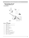
1
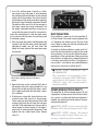
Owner’s Manual 19-38 Drum Sander OPERATING YOUR 19-38 DRUM SANDER Write your model and machine number in this manual for any questions or ordering information: CONTACT INFORMATION FOR SUPERMAX To the new SuperMax owner: SuperMax Tools 1275 Corporate Center Drive St. Paul, MN 55121 Phone: 651-454-3401 Toll Free: 888-454-3401 Fax: 651-454-3465 [email protected] www.supermaxtools.com SuperMax takes pride in our products and stands behind them with continuing service and support for our customers. Your SuperMax Sander was designed with several features that will bring a new dimension of productivity to your shop. Our goal at SuperMax is to develop machines that provide you with maximum performance, maximum economy and maximum utility. Your SuperMax 19-38 Drum Sander has features that will give you better results in less time in the years ahead. This sander is designed to be tailored to every project and features ultra-precise control for any sanding project. IDENTIFICATION INFORMATION Model # 71938-D Serial # _______________________________________________ Purchase Date ________________________________________ This sander is covered with a warranty and your dealer can answer any questions you may have. Additionally, we will always be here to offer support, service information, and product supplies and services. Dealer Info ___________________________________________ ________________________________________________________ ________________________________________________________ Before using your sander for the first time learn how to use it. This manual covers unpacking stepby-step, sander set up and fine-tuning the controls. Safety information is also provided to makes sure your process is hassle free. If you have any questions this manual will provide answers and you can also refer to our website or customer service for any updates or further details. WARRANTY The SuperMax 19-38 Sander comes with a twoyear limited warranty. We will provide replacement parts if found to be defective materially or in workmanship. SuperMax Team 2 MANUAL CONTENTS SAFETY WARNINGS . . . . . . . . . . . . . . . . . . 4 TECHNICAL SPECIFICATIONS. . . . . . . . . . 23 Wiring Diagram . . . . . . . . . . . . . . . . . . . . 23 Head Assembly. . . . . . . . . . . . . . . . . . . . . 24 Parts List—Head Assembly. . . . . . . . . . . 25 Conveyor and Motor Diagram. . . . . . . . 28 Parts List—Conveyor and Motor. . . . . . 29 ABOUT THE SUPERMAX 19-38 DRUM SANDER. . . . . . . . . . . . . . . . . 5 Specifications: . . . . . . . . . . . . . . . . . . . . . . 5 QUICK SET UP GUIDE TO UNPACKING. . . 6 SETTING UP THE 19-38 DRUM SANDER. 11 SUPPLY CHECKLIST AND ORDER INFORMATION. . . . . . . . . . . . . . . 31 Checking Drum Alignment . . . . . . . . . . . 11 Dust Collection. . . . . . . . . . . . . . . . . . . . . 12 Power And Electrical Safety. . . . . . . . . . 12 NOTES. . . . . . . . . . . . . . . . . . . . . . . . . . . . . 32 ABRASIVES. . . . . . . . . . . . . . . . . . . . . . . . . 13 Abrasive Selection Guide. . . . . . . . . . . . 13 Installing and Wrapping Abrasives. . . . 13 Abrasive Wrap Tension Adjustment. . . 14 Maximizing Abrasive Longevity . . . . . . 14 OPERATING THE 19-38 DRUM SANDER.15 Basic Operating Procedures Checklist . 15 Conveyor Belt Tension. . . . . . . . . . . . . . . 17 Conveyor Belt Tracking. . . . . . . . . . . . . . 17 Tension Roller Pressure . . . . . . . . . . . . . 17 TROUBLESHOOTING. . . . . . . . . . . . . . . . . 19 MAINTENANCE. . . . . . . . . . . . . . . . . . . . . 22 Monthly Maintenance Checklist. . . . . . 22 Cleaning the Machine. . . . . . . . . . . . . . . 22 Replacing Conveyor Belts . . . . . . . . . . . 22 3 SAFETY WARNINGS Caution, Safety First. When maintaining and operating this machine always put safety first. For your own protection read and study this manual and safety precautions before operating the machine. Always heed standard safety precautions including the following: • Wear eye protection when operating or cleaning the sander. • Always feed stock against drum rotation. • Never place hands or fingers under the tension roller, drum, or dust cover. • Keep hands and clothing away from operating drum. • Never operate the sander without the dust cover or guard in place. • Always maintain control of stock to avoid kickback. • Always disconnect electrical power before during any services or making any adjustment to the machine. • Do not modify the machine in any way. Any modification will be done at the user’s risk and will void the warranty and liability. • Always be safety conscious when operating or making adjustments on the sander. 4 ABOUT THE SUPERMAX 19-38 DRUM SANDER Specifications: ❖❖ Sanding Capacity Maximum Width: 38” (two passes) Minimum Length: 2 -1/4” This manual was designed to help familiarize you with your SuperMax 19-38 Drum Sander and to help you take advantage of its exclusive features. By understanding the major components and how they work together, you will be able to get the most from your investment. The SuperMax 19-38 Drum Sander system components are: Maximum Thickness: 4” typical Minimum Thickness: 1/32” typical ❖❖ Dimensions Length-36” Width-42” Height-51” on stand ❖❖ Drum 1. Height Adjustment Handle 5” in diameter 2.Shroud 1740 RPM 3. Depth Gauge ❖❖ Dust hood 4. Conveyor Speed Adjustment Hinged Back with 4”vaccum port 5. Drum ON/OFF Switch ❖❖ Height Adjustment 6. Conveyor Table 1/16” per revolution of the height adjustment handle 7. Tension Rollers 8. Drum Carriage Depth Gauge included ❖❖ Conveyor Motor Direct drive D.C. motor 1 Infinitely variable 1-10 feet per minute 2 8 ❖❖ Drive Motor (TEFC) 1-3/4HP 3 7 Continuous Duty ❖❖ Power Requirements 4 110 Volt, Single Phase 20 Amp service 5 6 5 QUICK SET UP GUIDE TO UNPACKING Your SuperMax 19-38 Drum Sander has been shipped mostly assembled from the factory. If any damage has occurred during shipping, notify the transportation company as soon as possible and ask for a damage and loss report. Then notify your dealer of any loss or damage. Before setting up make sure that the space is adequate for your new equipment. We also recommend that there is more than one person available for lifting and initial set up procedures. 2 pen BOX 1 that contains the main sanding unit. O Remove the cardboard liner. Open the plastic bag enclosing the sanding unit. The SuperMax 19-38 Drum Sander and stand is shipped in three boxes. NOTE: REQUIRED TOOLS All of the tools required for set up are shipped with your sander and stand. 1 ssemble the SuperMax 19-38 Drum Sander Open A Stand #71938-OP or alternatively, if you have chosen to use your own bench prepare the existing bench for the sander attachment. NOTE: HARDWARE NOTE: There will be a small container of hardware included with your sander. This container will include everything you need to set up your sander. See Open Stand #71938-OP manual included in the Open Stand shipping box for stand set-up and directions. 6 3 Cut each corner of BOX 1 to fold sides flat, providing access to sanding unit. 4 ith one or two helpers, place the sanding W unit on stand or bench. 5 emove the two wooden packing plates R from bottom of the sanding unit. Attach securely, use the enclosed wrench to tighten and keep wrench for future adjustments. NOTE: BOLTS These bolts that you just removed from the packing plates will work as your bolts for attaching the sander or as extra bolts for future replacement. 6 Install knob to height adjustment handle. First, finger tighten nut to knob. Thread stud from knob into hand wheel and tighten nut against hand wheel. Lift points marked. 19-38 DRUM SANDER OWNER’S MANUAL Quick Set Up Guide to Unpacking 7 7 T urn the handle and raise sanding head to higher position to remove packing block from under carriage arm. 8 ext prepare the unit for the installation of the N conveyor belt. You will remove the bolts at attachment points to allow the conveyor belt to be attached to the sanding unit. You will need to remove 4 bolts in total, two on each side of the unit. B. Next remove the 2 bolts on the inboard side of the conveyor belt. A. First remove the 2 bolts on the outboard side of the conveyor belt. NOTE: SILVER PLATE Leave the silver plate, which is near the fast lever and under the motor, in place when removing bolts. 19-38 DRUM SANDER OWNER’S MANUAL Quick Set Up Guide to Unpacking 8 9 Open BOX 2. Remove conveyor from packaging and place on sanding unit. The conveyor motor should be nearest to the main motor and depth gauge. should be tightened, but not so tight that the fast lever doesn’t move. The lever should be able to move from the down to up position easily. 10 Install lock washer and flat washer onto two socket heads (or hex head bolts) and install into flange of conveyor bed on inboard (motor side.) Keep support plate in place on inboard side and make sure the fast lever is positioned up. 11 Install two lock washers and two flat washers on the studs on outboard side of the conveyor belt. NOTE: FAST LEVER The fast lever should be in the upright position for installation of the sanding unit. The fast lever raises the inboard side of conveyor up. Do not ever tighten the bolts all the way down. The fast lever should always be able to be moved back and forth between and up/down position. The bolts 19-38 DRUM SANDER OWNER’S MANUAL Quick Set Up Guide to Unpacking 9 12 14 Tighten all nuts and bolts with wrench. C heck your power supply to make sure that it is adequate but do not plug the machine in to the power supply until it is fully setup. NOTE: FAST LEVER BOLT EXCEPTION Do not completely tighten bolts with fast lever. See Step 9 for reference. 13 P lug the short power cord that is attached to the motor into the outlet on the control box. This cord will provide switched power for the motor when the machine is plugged into the power source. The power cord that is wrapped around the gear motor is the power cord that must be plugged into a 110 Volt, 20 Amp outlet. 19-38 DRUM SANDER OWNER’S MANUAL Quick Set Up Guide to Unpacking 10 SETTING UP THE 19-38 DRUM SANDER CHECKING DRUM ALIGNMENT Checking the alignment before using the sanding drum is necessary to make sure that the drum is parallel. Your SuperMax 19-38 Sander should now be in place and ready for the final set-up. The sander was adjusted and aligned at the factory. However simple alignment checks will ensure that everything is in perfect order. Problems can be avoided if these essential checks and set-up procedures are performed prior to operation. 1. Remove the abrasive on the drum. Removing the abrasive is necessary to make sure that the adjustment is as accurate as possible and the texture on the abrasive will make the adjustment imprecise. 2. Locate the height adjustment handle for raising and lowering the sanding head. Remove abrasive from drum. Turning the height adjustment handle. NOTE: HEIGHT ADJUSTMENT HANDLE The height adjustment handle controls the drum height. Turning the handle raises or lowers the sanding head. One revolution of the handle raises or lowers the head by 1/16 of an inch. 11 3. Use a flat, uniform piece of wood as a thickness gauge. Insert the piece of wood between the conveyor belt and the drum on the inboard (right) side of the machine. You will not be able to pull and push the wood out without adjusting the height using the height adjustment handle. The tension rollers are set to be low enough so that items cannot pass easily underneath. Use the height adjustment handle as necessary to ensure that the piece of wood fits into position. Lower the sanding head so that the drum comes just in contact with the piece of wood being used as a thickness gauge. A B A) Socket head screw; B) Adjustment nut. DUST COLLECTION Dust collection is necessary for the SuperMax 1938 Drum Sander. The sander comes equipped with a 4” diameter dust exhaust port at the top of the cover. Check to make sure that the minimum dust requirements are sufficient. 4. After you place the piece of wood between the conveyor belt and the drum, rotate the height adjustment handle one full turn. After the height has been adjusted the wood piece may be removed. To attach to the dust collection system install a 4” hose from the dust collection system to the sander dust connection. For best results follow the recommendations of the manufacturer. When connecting dust collectors straight pipe is preferred because it is the least restrictive for airflow. If straight pipe is not possible Y’s and elbows are preferred because they are less restrictive to airflow than T’s. NOTE: DUST QUIREMENTS CAPACITY RE- The minimum recommended dust collection capacity is 600 CFM. Some applications will require more dust collection than the recommended minimum CFM. Wood piece being used as a thickness gauge. 5. Repeat the steps on the outboard (left) side of the machine using the same procedure. As you check look to make sure that the drum is parallel. A simple visual check that the drum is parallel is sufficient. 6. If the drum is not parallel, loosen the four socket head screws (See arrow A in above image. These screws are along the outboard side of the conveyor belt) and raise or lower the conveyor with the 7/16th adjustment nut (See arrow B in above image for exact location of the adjustment nut) to achieve parallel alignment. Then tighten the four socket head screws. Repeat steps 3-5. POWER AND ELECTRICAL SAFETY The SuperMax 19-38 Drum Sander requires 110 Volt, single-phase 20-Amp service. After the dust collection system is in place and the drum alignment is checked your machine should be ready to be powered up and operated. SAFETY NOTE: do not rewire the SuperMax 19-38 Drum Sander to 220 Volt. SAFETY NOTE: always disconnect electrical power before doing any servicing or adjusting of the machine. 19-38 DRUM SANDER OWNER’S MANUAL Setting Up the 19-38 Drum Sander 12 ABRASIVES the width of the slot. Release the clip lever to securely hold the wrap end in the fastener. Abrasive Selection Guide GRIT COMMON APPLICATION 24 Grit Abrasive planing, surfacing roughsawn boards, maximum stock removal glue removal 36 Grit Abrasive planing, surfacing roughsawn boards, maximum stock removal glue removal 50 Grit Surfacing and dimensioning boards, trueing warped boards 60 Grit Surfacing and dimensioning boards, trueing warped boards 80 Grit Light dimensioning, removal of planer ripples 100 Grit Light dimensioning, removal of planer ripples 120 Grit Light surfacing, minimal stock removal 150 Grit Finish sanding, minimal stock removal 180 Grit Finish sanding only, not for stock removal 220 Grit Finish sanding only, not for stock removal Take-up fastener. Take notice that for detail only the drum was removed to show the outboard take-up fastener. 2. Wind the wrap around the drum, being careful not to overlap the windings. The tapered cut of the wrap end should follow the edge of the drum. Continue to wrap the abrasive in a spiral fashion by rotating the drum with your left hand and guiding the wrap with your right hand. Successive windings of the wrap should be flush with previous windings without any overlap. Installing and Wrapping Abrasives Accurate attachment of the abrasive strip to the drum is critical to achieving the top performance from your SuperMax 19-38 Drum Sander. Wrapping Abrasives Pre-cut wraps have been factory tapered to the specific width of your drum. If you are cutting your own abrasive, use the wrap that came on the drum as a template. To attach a wrap to the drum, follow the procedure below. 1. Start on the left (outboard) side of the drum. Raise the clip lever on the left (outboard) side of the drum. Insert the tapered end through the slot and into the fastener so that it uses most of Leave a proper gap on the last wrap before it goes into the fastener. 13 Abrasive Wrap Tension Adjustment 3. Insert the tapered end through the slot in the right (inboard) end of the drum. Pull up on the clip lever to open the clip, and pull the take-up lever to the top. 4. After inserting the wrap end, release the clip lever. The take-up fastener is designed to automatically take up any slack caused by stretching of the abrasive wrap. The abrasive wrap may stretch enough in use to allow the take-up lever to reach its lowest position so it no longer is able to maintain tension on the wrap. If this occurs, it will be necessary to reset the take-up lever by raising it, pushing the wrap end into the slot, and then releasing the clip lever. The abrasive wrap may stretch enough in use to allow the take-up lever to reach its lowest position. If this occurs then tension is not longer maintained on the abrasive wrap. To fix this reset the take-up lever by raising it, pushing the abrasive wrap into the slot and then releasing the clip lever. Maximizing Abrasive Longevity A sandpaper cleaning stick may be used to remove deposits and help extend the life of the abrasive. 1. To use the cleaning stick, operate the sanding drum with the dust cover open and dust collection on. 2. Hold the cleaning stick against the rotating drum and move it along the drum surface. 3. Use a shop brush to remove any cleaning stick remnants from the drums before resuming sanding operations. Proper Abrasive Wrap Position Position the abrasive wrap in the slot with sufficient room between the inside of the slot and the tapered end of the wrap to allow it to be pulled into the drum as needed. If enough space is not left between the wrap and the inside of the slot the take-up fastener will not operate properly. SAFETY NOTE: For your own safety always wear eye protection while performing abrasive cleaning and take all precautions to avoid any contact with hands or clothing on the uncovered 19-38 DRUM SANDER OWNER’S MANUAL Abrasives 14 OPERATING THE 19-38 DRUM SANDER height as the abrasive in use. Place a flat piece of scrap stock under the drum with the abrasive in place. Lower the durm until the abrasive lightly touches the scrap piece of stock. Without changing the height, place the scrap stock under the thickness gauge. Adjust the bottom of the gauge by loosening the large nut and rotating the gauge up or down until it lightly touches the scrap piece of stock. Tighten the large nut. Now the stock can be placed under the thickness gauge and the drum lowered until the gauge lightly touches the stock to be sanded. By using this method the stock does not need to be carried under the drum to set depth of cut. Your sander will be able to perform an infinite variety of sanding projects all designed to your specifications. With some time and experimentation the proper setting and technique for each job will become apparent. Basic Operating Procedures Checklist 1. SET DRUM DEPTH OF CUT p. 16 2. START SANDING DRUM p. 16 3. START CONVEYOR AND SELECT FEED RATE p. 16 4. START DUST COLLECTING SYSTEM p. 17 5. FEED STOCK THROUGH UNIT p. 17 A good rule of thumb when sanding is to place the stock under the drum and lower the sanding head until the stock is in contact with the drum but the drum can still be rotated by hand. Normally as the depth of cut is adjusted the handle will be rotated no more than a third of a turn at any time. INTELLISAND will help with this process. Drum Depth of Cut etermining the depth of cut is the most importD ant operating procedure decision. It may take some experimentation to determine the proper depth of cut. The crucial variables to keep in mind are abrasive grit, type of wood, project type, and conveyor feed rate. We recommend practicing on a scrap of wood prior to sanding a project. NOTE: INTELLISAND INTELLISAND will automatically adjust the conveyor feed rate if an excess load is detected. This prevents excessive gouging, reduces the risk of burning and protects the machine from overload or stalling. The red light by the adjustment knob will come on when INTELLISAND is operating. When the load is decreased, INTELLISAND will automatically increase the feed rate to the pre-selected speed. NOTE: Height Adjustment Handle The height adjustment handle controls the drum height. Turning the handle raises or lowers the sanding head. One revolution of the handle raises or lowers the head by 1/16 of an inch. Thickness gauge bolt. Another method to set depth of cut is to use the thickness gauge attached to the inboard side of the sander. The gauge must be adjusted to the same 15 Conveyor and Speed Rate ——Sanding Imperfect or Tall Stock After the depth of cut has been determined, selecting the proper feed rate is essential. For finish sanding the best finish is usually achieved with a slow to moderate feed rate. This allows for the most revolutions of the drum per inch of sanding. Faster feed rates can be used as long as the machine is not over-stressed. To avoid bodily injury take special care when sanding stock that is twisted, bowed or otherwise varied in thickness from end to end. If possible support such stock as it is being sanded to keep it from slipping or tipping. Use extra roller stand, assistance from another person, or hand pressure on the stock to minimize potentially hazardous situations. When finish sanding with grits finer than 80, the best finish can usually be obtained if INTELLISAND does not engage. If INTELLISAND does slow the conveyor when finish sanding, it is best to make another sanding pass without changing the thickness setting and sand again. When sanding high or tall stock special attention is necessary to prevent tipping or slippage. Extra care may be needed as the stock exits the machine. ——Sanding Stock Wider than the Drum When dealing with stock that is wider than the drum the fast lever will be very useful. Wide stock may require extra space between the drum and conveyor along the outboard edge. The extra space will help prevent and overlap line or ridge from developing along the sanded part where it extends beyond the sanding drum. Stock Feeding Operation To feed stock through the sander rest the stock and hold the stock to be sanded on the conveyor table. Allow the conveyor to carry the stock into the drum. Once the stock is halfway through, reposition yourself to the outfeed side of the machine to receive and control the stock as it exits the unit. NOTE: FAST LEVER The fast lever raises the outboard side of the table .003. Never tighten the bolts all the way down. The fast lever should always be able to be moved back and forth between and up/down position. The bolts should be tightened, but not so tight that the fast lever doesn’t move. Stock Feeding Maximum Performance The built-in versatility of the SuperMax 19-38 Drum Sander allows it to be used for a wide range of tasks. Learning to use the multiple controls to make adjustments will allow you to fine tune the machine for maximum results no matter what the job. The best results come from experimenting with different machine adjustments to best fit the job at hand. ——Sanding Multiple Pieces Simultaneously When sanding multiple pieces at once, make sure to stagger or step the pieces across the width of the conveyor belt. This position provides better contact with the tension rollers. It is best to only process multiple pieces that are all of a similar thickness. If there is a thickness difference the thinner pieces may not come in contact with the tension rollers and may slip on the conveyor belt 19-38 DRUM SANDER OWNER’S MANUAL Operating The 19-38 Drum Sander 16 Conveyor Belt Tracking Adjusting the fast lever allows for easy alteration of the drum position in relationship to the conveyor without changing the initial drum alignment. Belt tracking adjustments are made while the conveyor belt is running. After the proper belt tension is obtained turn the conveyor unit on and set it at the fastest speed setting. Watch for a tendency of the conveyor belt to drift to one side of the conveyor. To adjust the belt tracking, tighten the takeup screw nut on the side the belt is drifting toward, and loosen the take-up screw nut on the opposite side. Adjusting the take-up screw nuts on either side of the conveyor allows belt-tracking adjustments to be made without affecting belt tension. Note: Adjust the take-up screw nuts only 1/4 turn at a time. Then allow time for the belt to react to the adjustments before proceeding further. Avoid over-adjustments. It is a good idea to test a scrap piece of stock prior to sanding. If a line or ridge is still visible after adjusting the fast lever additional adjustments can be made to the drum alignment. After sanding stock wider than the drum the fast lever should be adjusted back to the original position. The fast lever should be put into the up position. ——Stock Feeding Position and Angle Positioning the stock at an angle will allow the most effective stock removal and least loading on the abrasives. Feeding stock straight through yields the widest sanding capacity and least noticeable scratch pattern. Tension Roller Pressure The tension roller pressure is factory set and should be adequate. However, the pressure of each roller can be adjusted as needed. To increase the tension turn the tension adjusting screw clockwise ¼ revolution at a time. To decrease tension turn the adjusting screw counter-clockwise ¼ revolution at a time. Some pieces because of their dimensions will need to be fed into the sander at a 90-degree angle, which will be perpendicular to the drum. However, even a slight offset angle of the stock can provide for more effective sanding. Final pass sanding should be done following the grain pattern. Conveyor Belt Tension Insufficient belt tension will cause slippage of conveyor belt on the drive roller during sanding operation. The conveyor belt is too loose if it can be stopped by hand pressure applied directly to the top of the conveyor belt. Excessive belt tension can result in bent rollers, premature wearing of the bronze bushings or conveyor belt To adjust the tension of the conveyor belt, first adjust the take-up screw nut on both sides of the conveyor to obtain approximately equal tension on both sides of the belt when taut. 19-38 DRUM SANDER OWNER’S MANUAL Operating The 19-38 Drum Sander 17 NOTE: TENSION ROLLER PRESSURE WARNING SIGNS It is important to pay attention to the tension roller pressure because too little pressure can result in slippage of stock on conveyor belt and kick back. Too much tension can cause snipe when sanding. 19-38 DRUM SANDER OWNER’S MANUAL Operating The 19-38 Drum Sander 18 TROUBLESHOOTING If you are experiencing a problem affecting the machine’s performance, check the following for potential causes and solutions; it may also pay to review the previous sections in this manual on setting up and operating your machine. PROBLEM Conveyor motor oscillates. POSSIBLE CAUSE 1. Motor not properly aligned. 2. Shaft collar or bushing worn. 3. Drive roller bent. PROBLEM Motors do not start. SOLUTION POSSIBLE CAUSE Loosen housing bolts, run the motor, and re-tighten bolts. 1. Main power cord unplugged. 2. Motor cord unplugged from receptacle near power-feed motor. 3. Circuit fuse blown or circuit breaker tripped. Replace the shaft collar. Replace the drive roller. SOLUTION PROBLEM Plug in primary power cord. Drum motor or conveyor gear motor stalls. Plug in motor and inverter cord on the machine itself. POSSIBLE CAUSE Replace fuse or retrip breaker (after determining cause). SOLUTION 1. Excessive depth of cut. Reduce depth of cut. PROBLEM Reduce feed rate. Motor Overloads PROBLEM POSSIBLE CAUSE Conveyor rollers run intermittently. 1. Inadequate circuit. 2. Machine overloaded by the material. POSSIBLE CAUSE 1. Shaft coupling loose. SOLUTION SOLUTION Check electrical requirements Align shaft flats of gear motor and drive roller; tighten shaft coupling set screws. Use slower feed rate; slower RPM; reduce depth of cut. Adjust belt tension. 19 PROBLEM PROBLEM Conveyor belt slips on drive roller. Conveyor belt tracks to one side, or oscillates from side to side. POSSIBLE CAUSE POSSIBLE CAUSE 1. Improper conveyor belt tension. 2. Excessive depth of cut. 1. Belt out of adjustment. 2. Drive or driven conveyor belt rollers misaligned. 3. Conveyor table not flat and square. 4. Conveyor belt worn. 5. Drive roller worn or damaged. SOLUTION Adjust belt tension. Reduce depth of cut. Reduce feed rate. SOLUTION PROBLEM Readjust belt Stock slips on conveyor belt. Readjust by leveling machine POSSIBLE CAUSE Replace conveyor belt 1. Excessive depth of cut. 2. Tension rollers too high. 3. Excessive feed rate. 4. Dirty or worn conveyor belt. Replace abrasives. PROBLEM Drum height adjustment works improperly. POSSIBLE CAUSE SOLUTION 1. Improper adjustment of height control. 2. Bearing worn. 3. Sawdust dirt or debris in threads of height adjustment rods. Reduce depth of cut. Lower tension rollers. Reduce feed rate. Clean or replace conveyor belt. SOLUTION Readjust height control Replace bearing Clean and oil threads PROBLEM Knocking sound while running. POSSIBLE CAUSE 1. Wear on the drum bearings. SOLUTION Replace bearings. Contact dealer. 19-38 DRUM SANDER OWNER’S MANUAL Troubleshooting 20 PROBLEM PROBLEM Sniping of wood (gouging near end of board). Gouging of wood. POSSIBLE CAUSE POSSIBLE CAUSE 1. Inadequate support of stock. 2. Conveyor drive or driven rollers higher than conveyor bed. 3. Excessive tension roller pressure. 1. Conveyor belt is too loose. 2. Excessive depth of cut. 3. Wood slipping on conveyor due to lack of contact. SOLUTION SOLUTION Use roller stands to support stock. Adjust belt tension. Readjust rollers Reduce depth of cut, decrease RPM. Use alternate feeding procedure PROBLEM Burning of wood or melting of finish. PROBLEM POSSIBLE CAUSE Burning paper or abrasive. 1. Feed rate too slow. 2. Excessive depth of cut. POSSIBLE CAUSE 1. Overlapped paper. 2. Improper gap in abrasive paper. The gap should be approximately 1/16. SOLUTION Increase feed rate. SOLUTION Reduce depth of cut. Adjust the abrasive so that there are proper gaps and room. 19-38 DRUM SANDER OWNER’S MANUAL Troubleshooting 21 MAINTENANCE Monthly Maintenance Checklist 6. Remove the two nuts and washers (outboard side). 7. Lift the conveyor and remove it from the sander. 8. Stand conveyor on motor side. 9. Avoid tearing the belt on any edges underneath the conveyor bed during removal. Reverse the procedure for re-installation and re-install the conveyor bed to sander. For best results perform the following procedures on a monthly basis: • Lubricate conveyor bushings and check for wear. • Lubricate with a dry lubricant spray all of the moving parts, such as threaded rods and washers. • Clean dust from conveyor belt. • Check all set screws for tightness. • Clean drum and abrasives if necessary. Cleaning the Machine The sander may need to be cleaned more frequently depending upon frequency of use. The drum and the conveyor belt need to be clean. Allowing excess build-up of dust and debris can adversely affect performance and increase the likelihood of slippage on the conveyor belt. Sweep the conveyor belt clean after all operations. When cleaning dust from the drum leave the dust collection system on. Replacing Conveyor Belts To replace the conveyor belt, the conveyor assembly must be removed from the machine. 1. Raise the drum carriage to its highest position using the height adjustment handle. 2. Turn off power source to machine. 3. Unplug main drive motor and inverter from receptacle (in gear motor assembly). 4. Loosen the conveyor take-up screws to relieve belt tension and slide the driven roller fully inward. 5. Remove the two bolts (inboard side) that attach the conveyor assembly to the base. 22 TECHNICAL SPECIFICATIONS Wiring Diagram Wiring Diagram TO GEAR MOTOR CONVEYOR 23 Head Assembly 19-38 DRUM SANDER OWNER’S MANUAL Technical Specifications 24 Parts List—Head Assembly IndexPart No.No. Description Size Qty. 1 ............ 480DS-101 .................... Motor ......................................................................................................... 1 .............. 480DS-101MFC ............ Motor Fan Cover ...................................................................................... 1 2 ........... 480BS-134 .................... Strain Relief, motor ........................................7N-2 ................................ 1 3 ........... 480DS-103 ................... Main Cord, Motor to Control Box.......................................................... 1 4 ........... 480BS-104 ................... Key .....................................................................3/16”SQx3/4” ................. 2 5 ........... 480BS-105 ................... Nylon Insert Lock Nut ....................................5/16”-24 ......................... 4 6 ........... 480BS-106 ................... Flat Washer ......................................................5/16” .............................. 9 7 ............ 480BS-107 .................... Oilite Washer ........................................................................................... 8 8 ........... 480BS-108 ................... Motor Plate ............................................................................................... 1 9 ........... 480BS-109 ................... Set Screw ..........................................................#8-32x1/4” ..................... 1 10 ......... 480BS-110 .................... Hex Cap Screw .................................................5/16”-18x1-1/4” ............. 6 11 .......... 480BS-111 ..................... Lock Washer .....................................................3/8” ................................. 4 12 .......... 480BS-112 .................... Socket Head Cap Screw .................................3/8”-16x1-1/2” ............... 4 13 .......... 480BS-113 .................... Set Screw ..........................................................1/4”-20x1/4” ................... 5 14 .......... 480BS-114 .................... Coupling ..................................................................................................... 2 15 .......... 480BS-115 .................... Coupling Spider ........................................................................................ 1 16 .......... 480BS-116 .................... Depth Gauge Plate .................................................................................. 1 17 .......... 480BS-117 .................... Screw, Phil Pan Head ......................................M4x0.7x6 ..................... 14 18 .......... 480BS-118 .................... Label, Depth Gauge (inch) ..................................................................... 1 19 .......... 480BS-119 .................... Depth Gauge Pointer .............................................................................. 1 20 ......... 480BS-120 ................... Knob ........................................................................................................... 1 21 .......... 480BS-121 .................... Height Adjustment Handle ................................................................... 1 22 ......... 480BS-122 .................... Nylon Insert Lock Nut ....................................5/8”-11 ............................ 1 23 ......... 480BS-123 .................... Height Adjustment Screw ...................................................................... 1 24 ......... 480BS-124 .................... E-Ring.................................................................E12 ................................... 1 25 ......... 480BS-125 .................... Thrust Bearing .................................................51103 ............................... 1 26 ......... 480BS-126 .................... Shroud ........................................................................................................ 1 27 ......... 480BS-127 .................... Stud ............................................................................................................ 4 28 ......... 480BS-128 ................... Hex Cap Screw .................................................3/8”-16x1-1/4” ............... 4 29 ......... 480BS-129 ................... Flat Washer ......................................................3/8” ................................ 8 30 ......... 480BS-130 ................... Hinge .......................................................................................................... 2 19-38 DRUM SANDER OWNER’S MANUAL Technical Specifications 25 Parts List—Head Assembly (continued) IndexPart No.No. Description Size Qty. 31 .......... 480DS-131 .................... Dust Cover ................................................................................................. 1 32 ......... 480BS-132 .................... Handle ........................................................................................................ 1 33 ......... 480BS-133 .................... Pan Head Machine Screw .............................#8x1/2” .......................... 2 34 ......... 480DS-134 ................... Lock Washer .....................................................M3 ................................... 2 35 ......... 480BS-135 .................... Dust Cover Latch ...................................................................................... 1 36 ......... 480DS-136 ................... Phillips Flat Head Screw ................................M3x0.5x10 ..................... 2 37 .......... 480DS-137 .................... Sanding Drum .................................................. 1 38 ......... 480DS-138 ................... Nylon Insert Lock Nut ....................................M3x0.5 ........................... 2 39 ......... 480DS-139 ................... Inboard Abrasive Fastener ..................................................................... 1 40 ......... 480DS-140 ................... Outboard Abrasive Fastener ................................................................. 1 41 .......... 480DS-141 .................... Carriage Bolt ....................................................5/16”-18x1” .................... 4 42 ......... 480DS-142 ................... Bearing ..............................................................6205ZZ ........................... 2 43 ......... 480DS-143 ................... C-Ring ................................................................S25 .................................. 2 44 ......... 480DS-144 ................... Drum Carriage .......................................................................................... 1 45 ......... 480BS-145 .................... Flat Washer ......................................................1/4” .................................. 5 46 ......... 480BS-146 ................... Round Socket Head Cap Screw ....................1/4”-20x1” ...................... 4 47 ......... 480BS-147 .................... Flat Washer ......................................................5/16” ............................... 4 48 ......... 480DS-148 ................... Bearing Seat .............................................................................................. 2 49 ......... 480BS-149 ................... Hex Cap Screw w/ Washer ............................#10-24x3/8” .................. 2 50 ......... 480BS-150 ................... Dust Cover Catch ..................................................................................... 1 51 .......... 480BS-151 .................... Stud ............................................................................................................ 1 52 ......... 480BS-152 .................... Spring ......................................................................................................... 1 53 ......... 480BS-153 .................... Tension Roller ........................................................................................... 2 54 ......... 480BS-154 .................... Bushing, Oilite .......................................................................................... 4 55 ......... 480BS-155 .................... Tension Roller Bracket, Inner Left ........................................................ 1 56 ......... 480BS-156 .................... Screw .................................................................#8-32x1”......................... 4 57 .......... 480BS-157 .................... Spring, Tension Roller ............................................................................. 4 58 ......... 480BS-158 ................... Tension Roller Bracket, Inner Right ...................................................... 1 59 ......... 480BS-159 .................... Pad, Bracket-Tension Roller ................................................................... 2 60 ......... 480BS-160 ................... Bracket ....................................................................................................... 2 61 .......... 480BS-161 .................... Plate ........................................................................................................... 1 19-38 DRUM SANDER OWNER’S MANUAL Technical Specifications 26 Parts List—Head Assembly (continued) IndexPart No.No. Description Size Qty. 62 ......... 480BS-162 .................... Base ............................................................................................................ 1 63 ......... 480BS-163 .................... Adjusting Lever (FAST)............................................................................. 1 64 ......... 480BS-164 ................... Adjusting Rod ........................................................................................... 1 65 ......... 480BS-165 .................... Height Adjusting Plate ........................................................................... 1 66 ......... 480BS-166 ................... Round Socket Head Cap Screw ....................5/16”-18x1/2” ................. 4 67 ......... 480BS-167 .................... Lock Washer .....................................................5/16” ............................... 5 68 ......... 480BS-168 ................... Spring ......................................................................................................... 3 69 ......... 480BS-169 ................... Nylon Insert Lock Nut ....................................1/4”-20 ............................ 1 70 ......... 480DS-170 ................... Socket Head Cap Screw .................................M8x1.25x40 ................... 1 71 .......... 480DS-171 .................... Hex Nut w/ Washer ........................................5/16”-18 .......................... 4 72 ......... 480DS-172 .................... Block, Measuring Device ........................................................................ 1 73 ......... 480DS-173 .................... Hex Nut .............................................................M12x1.75 ......................... 1 74 ......... 480DS-174 .................... Stop Bolt .................................................................................................... 1 75 ......... 480DS-175 .................... Screw .................................................................M3x0.5x6 ....................... 2 76 ......... 480DS-176 ................... Lower Fixed Plate, DRO .......................................................................... 1 77 .......... 480BS-177 .................... Hex Cap Screw .................................................3/8”-16x3/4” .................. 4 78 ......... 480DS-178 ................... Hex Nut .............................................................M4x0.7 ........................... 1 79 ......... 480BS-179 .................... Tension Roller Bracket, Outer Right ..................................................... 1 80 ......... 480BS-180 ................... Tension Roller Bracket, Outer Left ....................................................... 1 81 .......... 480BS-181 .................... E-Ring.................................................................E5 .................................... 1 82 ......... 480DS-182 ................... Upper Fixed Plate, DRO .......................................................................... 1 83 ......... 480DS-183 ................... Battery Cover ........................................................................................... 1 84 ......... 480DS-184 ................... Label ........................................................................................................... 1 85 ......... 480BS-185 ................... Height Direction Label ............................................................................ 1 86 ......... 480BS-186 ................... Maintenance Label .................................................................................. 1 87 ......... 480BS-187 .................... Warning Label ........................................................................................... 1 88 ......... 480DS-188 ................... Battery ....................................................................................................... 1 89 ......... 480DS-189 ................... Digital Readout Assembly (optional) .................................................. 1 90 ......... 635DS-280 ................... Fastener Tool (optional) ......................................................................... 1 19-38 DRUM SANDER OWNER’S MANUAL Technical Specifications 27 Conveyor and Motor Diagram 19-38 DRUM SANDER OWNER’S MANUAL Technical Specifications 28 Parts List—Conveyor and Motor IndexPart No.No. Description Size Qty. 1 ............ 480BS-201 ................... Gear Motor .......................................................90 VDC ........................... 1 2 ........... 480DS-202 ................... Strain Relief, Power Cord ..............................6P3-4 .............................. 1 3 ........... 480DS-203 ................... Power Cord ................................................................................................ 1 4 ........... 480BS-204 ................... Flat Washer ......................................................5/16” ............................... 4 5 ........... 480BS-205 ................... Socket Head Cap Screw .................................#10-32x1/2” ................... 4 6 ........... 480BS-206 ................... Tracking Kit (optional) ............................................................................ 2 7 ............ 480BS-207 ................... Knob ........................................................................................................... 1 8 ........... 480BS-208 ................... Speed Adjustment Label ........................................................................ 1 9 ........... 480BS-209 ................... Wiring Guard ............................................................................................. 1 10 ......... 480DS-210 ................... Controller ................................................................................................... 1 11 .......... 480DS-211 .................... Control Housing Bracket ........................................................................ 1 12 .......... 480BS-212 .................... Pan Head Self-Tapping Screw ......................5/32”x1/2” ...................... 2 13 .......... 480DS-213 ................... Receptacle, Main Cord ............................................................................ 1 14 .......... 480BS-214 .................... Screw .................................................................#10-32x1/2” ................... 1 15 .......... 480BS-215 .................... Washer, Lock-Int. Tooth .................................#10 .................................. 2 16 .......... 480BS-216 .................... Hex Nut .............................................................#10-32 ............................ 2 17 .......... 480BS-217 .................... Screw, Hex Head-Slotted ..............................#10-32x3/8” .................. 5 18 .......... 480BS-218 ................... Screw, Phil Pan Head ......................................#6-32x1/2” .................... 2 19 .......... 480BS-219 ................... Switch, ON/OFF ........................................................................................ 1 20 ......... 480BS-220 ................... Coupler, Shaft ........................................................................................... 1 21 .......... 480BS-113 .................... Set Screw ..........................................................1/4”-20x1/4” ................... 2 22 ......... 480BS-222 ................... Bracket, Base- Controller ....................................................................... 1 23 ......... 480BS-223 ................... Cover, Base-Control Housing ................................................................. 1 24 ......... 480BS-224 ................... Hex Cap Screw .................................................1/4”-20x3/4” ................ 12 25 ......... 480BS-225 ................... Washer, Wave ..................................................1/4” .................................. 4 26 ......... 480BS-145 .................... Flat Washer ......................................................1/4” .................................. 4 27 ......... 480BS-227 ................... Bracket, Take Up-Slide ............................................................................ 2 28 ......... 480BS-154 .................... Bushing, Oilite. ......................................................................................... 4 29 ......... 480BS-229 ................... Roller, Driven ............................................................................................ 1 30 ......... 480BS-230 ................... Wrench ....................................................................................................... 2 31 .......... 480BS-231 .................... Hex Nut .............................................................1/4”-20 ............................ 2 19-38 DRUM SANDER OWNER’S MANUAL Technical Specifications 29 Parts List—Conveyor and Motor (continued) IndexPart No.No. Description Size Qty. 32 ......... 480BS-232 ................... Washer, Lock-Int. Tooth .................................1/4” .................................. 2 33 ......... 480BS-233 ................... Screw, Round Head- Slotted ........................1/4”-20x1-3/4” ............... 2 34 ......... 480BS-234 ................... Bracket, Take Up-Base ............................................................................ 2 35 ......... 480BS-167 .................... Lock Washer .....................................................5/16” ............................... 4 36 ......... 480BS-236 ................... Roller, Drive ............................................................................................... 1 37 .......... 480BS-237 ................... Bracket, Support-Drive Roller ............................................................... 1 38 ......... 480BS-238 ................... Bed, Conveyor .......................................................................................... 1 39 ......... 480BS-239 ................... Socket Head Cap Screw .................................5/16”-18x3/4” ................ 2 40 ......... 480DS-240 .................. Belt Conveyor, Abrasive (Not Shown) ................................................. 1 41 .......... 480BS-204 ................... Flat Washer ......................................................5/16” ............................... 1 42 ......... 480BS-242 ................... Hex Nut .............................................................5/16“-24 ......................... 1 43 ......... 480BS-243 ................... Slotted Set Screw ............................................#8-36x5/16” .................. 1 44 ......... 480BS-244 ................... Strain Relief, Gear Motor ..............................6N-4 ............................... 1 45 ......... 480BS-245 ................... Hex Nut .............................................................5/16”-18 .......................... 2 19-38 DRUM SANDER OWNER’S MANUAL Technical Specifications 30 SUPPLY CHECKLIST AND ORDER INFORMATION Individual Wrap, Pre-Cut Abrasive Cut to taper and length of drum. OPTIONAL ACCESSORIES Abrasive Cleaning Stick, Part # 59120 8” x 1-1/2” x 1-1/2” Closed Stand, Part # 71938-CL Optional upgrade for 19-38 Drum Sander. Built in storage and lockable wheels. Digital Read Out, Part # 71938-DRO Digital Read Out displays sanding thickness in inches with fractions or millimeters. Comes with brackets for attaching it to the machine. Casters, Set of 4, Part # 98-0130 Swivel and lock casters, compatible with Open Stand. Abrasive Conveyor Belt, Part # 60-0322 100 grit abrasive surface with reinforced backing. ABRASIVES 3-Pack Box, Pre-Cut Abrasive Wraps Cut to taper and length of drum. 60-19-036 36 Grit: 3-wraps in a box 60-19-060 60 Grit: 3-wraps in a box 60-19-080 80 Grit: 3-wraps in a box 60-19-100 100 Grit: 3-wraps in a box 60-19-120 120 Grit: 3-wraps in a box 60-19-150 150 Grit: 3-wraps in a box 60-19-180 180 Grit: 3-wraps in a box 60-19-220 220 Grit: 3-wraps in a box 619-060-1 60 Grit: Individual Wrap 619-080-1 80 Grit: Individual Wrap 619-100-1 100 Grit: Individual Wrap 619-120-1 120 Grit: Individual Wrap 619-150-1 150 Grit: Individual Wrap 619-180-1 180 Grit: Individual Wrap 619-220-1 220 Grit: Individual Wrap Please note: Prices and product offerings subject to change. CONVEYOR BELT 36, 80, 120 Grit: 3 wraps total 36 Grit: Individual Wrap TO ORDER: Call your local dealer or call SuperMax Tools direct at 888-454-3401. Infeed/Outfeed Tables, Part # 71938-7 Dimensions 10”D x 23” W. Adds approx. 12” to either side of conveyor. Four bolts for assembly, tables at fixed height. 60-19-000 619-036-1 31 NOTES 32