1
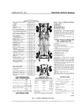
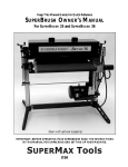
Brake Lathes
Repair Procedures—Disc Feed
Mechanism Model 7751-B
Models 4000, 4100 & 7500 Only
Crossfeed Assembly
Figure 1
Part
Item Qty
No. Description
9
1 909835 Crossfeed
10
3 906874 Race
11
1 909626 Crossfeed Handwheel Assembly
12
1 906839 Screw, Set
13
1 909634 Dial
14
1 909611 Spring, Dial
15
1 909633 Handwheel
16
1 903026 Crank, Handwheel
20
1 900220 Screw, Set
21
1 902064 Spring
22
1 909836 Plug
25
1 906873 Bearing, Needle Thrust
26
1 903211-1 Lead Screw Assembly
29
1 910346 Bar, Guide
31
1 907751B Gearbox Assy., 4000/4100/7500
32
4 900237 Screw, Cap 4000/4100/7500
33
4
901127 Screw, Cap 3000/7700
34
1 903007 Cap, Lead Screw, 3000/7700
35
1 900237 Nut, 3000/7700
Service Manual —AMMCO Drum & Disc Brake Lathes • 3
Brake Lathes
Removal Procedure 7751-B
Disassembly Procedure 7751-B
(Refer to figure 1 & 2)
(Refer to figure 2)
1. Turn the power to the machine off.
1. Remove (2) #43 and (2) #42 Screws.
2. Place #46 Shifter Handle (fig. 2) on #31 Gearbox
into slow feed and hold it in place.
3. Turn #11 Crossfeed Handwheel at least ten (10)
turns counterclockwise to disengage #7 Universal
Coupling (fig. 2) from #26 Lead Screw.
4. Continue turning #11 Crossfeed Handwheel, until
#9 Crossfeed no longer feeds out of the frame.
5. Remove (4) #32 Cap Screws holding #31 Gearbox
to the frame of the lathe.
2. Separate item #35 Gear Case Cover from item #1
Gear Case.
3. Remove #52 Set Screw.
4. Remove #46 Shifter Handle and #27 Key from #34
Shaft.
5. Remove #40 Screw, and #39 Washer.
6. Remove (2) #37 Screws.
7. Remove #6 Drive Rod and Coupling.
6. Remove #31 Gearbox from the frame.
7. If needed, replace the lead screw nut using the
#73 Lead Screw Nut Kit (fig. 2).
CAUTION
Do not allow #14 Drive Rod to separate from
#18 Drive Gear, unless repair is needed. This
prevents disengagement of #15 Dowel Pins
from #14 Drive Rod and #18 Drive Gear.
8. Remove items #A, #B, #C, #D, and #E from #71
Shifter and Intermediate Gear Assembly.
9. Retrieve #20 Bone Shim Washer.
10. Remove #21 Shifter Shaft.
11. Remove #34 Shifter Shaft in the direction of #24
Retaining Ring and retrieve #27 Key before completely
removing #34 Shifter Shaft from housing.
12. Retrieve #F shift half.
13. Retrieve #30 Coarse Feed Gear.
Notes On Disassembly:
A. Item #21 Shifter Shaft should be replaced
as an assembly (except #29) due to the
internal Retaining Ring #26 holding #28 Fine
Feed Gear to #25 Clutch Shaft. Disassembly
usually results in breakage of #25 Clutch
Shaft.
B. Items #A, #B, #C, #D, #E, and #F are sold
as assembly #924516 only.
Disassembly and cleaning - 45 minutes.
4 • Service Manual —AMMCO Drum & Disc Brake Lathes
Brake Lathes
Assembly Procedure 7751-B
Installation Procedure 7751-B
(Refer to figure 2)
(Refer to figure 1)
1. Install #34 Shifter Shaft, #27 Key, and #F Shifter Half
in #35 Gear Case Cover.
2. Install #24 Retaining Ring on #34 Shifter Shaft.
3. Install #27 Key and #46 Shifter Handle on #34 Shifter
Shaft.
4. Install and tighten #52 Set Screw in #46 Shifter
Handle.
5. Install #A, #B, #C, #D, #E from #71 Shifter and
Intermediate Gear Assembly.
1. Mount the gear box to the frame with the four #32
Screws. Do not tighten.
2. Before tightening #32 Screws, align #65 Coupling
(fig. 2) with the pin in the driven pulley by rotating the
#31 Gearbox on its axis (the amount of rotation is limited
by the mounting bolts).
3. Now tighten #32 Screws.
4. Crank #11 Crossfeed Handwheel clockwise to
engage the #9 cross feed with #31 Gearbox.
5. Continue to turn #11 Crossfeed Handwheel until #9
Crossfeed is about halfway engaged with the frame.
6. Install #6 Drive Rod and Coupling.
6. Place #46 Shifter Handle (fig. 2) into the slow feed
position.
CAUTION
Do not separate #14 Drive Rod from #18 Drive
Gear.
7. Install (2) #37 Screws and tighten.
8. Install #39 Washer and #40 Screw.
9. Place #30 Coarse Feed Gear into #35 Gear Case
Cover and line up hole in #30 Coarse Feed Gear with
bore in #35 Gear Case Cover.
10. Install #21 Shifter Shaft.
CAUTION
7. Insert a 10" drive extension into the tube, protruding
from the back of #35 Gear Case Cover (fig. 2).
8. Exert light pressure against #40 Screw (fig. 2)
(installed on #14 Drive Rod (fig. 2), inside the tube, with
the wrench extension. This makes contact between #7
Universal Coupling (fig. 2) and #26 Lead Screw. Continue
to apply light pressure.
9. Turn #11 Crossfeed Handwheel slowly counterclockwise a few turns to locate lead threads on #7 Universal
Coupling (fig. 2) and #26 Lead Screw.
10. Now turn #11 Crossfeed Handwheel clockwise to
engage the threads.
Make sure #29 Clutch meshes properly with
#28 Fine Feed Gear.
11. Tighten with #11 Crossfeed Handwheel while holding #46 Shifter Handle (fig. 2) in slow feed.
11. Install #20 Bone Shim Washer on #71 Shifter and
Intermediate Gear Assembly.
Note: To insure all parts are well lubricated
apply a light coat of AMMCO p/n 926391
grease to all parts prior to assembly. Fill gear
case with grease before final assembly.
12. To assemble #35 Gear Case Cover (with all the
gears in place) and #1 Gear Case, line up #D and #25
Clutch Shafts with the two bores on the inside of #1 Gear
Case and close the gear box.
13. Install (2) #43 and (2) #42 Screws and tighten.
Service Manual —AMMCO Drum & Disc Brake Lathes • 5
Brake Lathes
Disc Brake Feed Mechanism 7751-B
Part
Item Qty
No.
1
1 910870
2
4 903221
3
2 903910
5
1 907790
4
1
*6
1 940718
*7
1 940719
*9
1 940717
*10
1 940403
14
1 907774
15
2 906937
16
2 906973
17
1 907775
18
1 907778
20
1 906350
21
1 909814
22
1 907994
23
1 904006
24
2 905613
25
1 907764
26
1 906138
27
5 903176
28
1 909816
29
1 909813
30
1 909812
34
1 907748
35
1 907902
36
1 907783
37
2 903221
39
1 904789
40
1 906254
41
1 906974
42
2 906392
43
2 906391
44
1 907747
45
2 904508
Description
Gear Case Assembly
Screw, Socket Head
Washer, Lock
Case, Gear
Drive Rod and Coupling Assy.
Universal Coupling Assy.
Coupler
Pin, Roll
Rod, Drive
Pin, Dowel
Washer, Thrust
Trap
Gear, Drive
Washer, Bone Shim
Shifter Shaft Assy.
Gear, Helix
Pin, Roll
Ring, Retaining
Shaft, Clutch
Ring, Retaining
Key, Woodruff
Gear, Fine Feed
Clutch
Gear, Coarse Feed
Shaft, Shift
Gear Case Cover and Tube Assy.
Tube
Screw, Socket Hd. Cap
Washer
Screw, Socket Hd. Cap
Cap, Tube
Screw, Hex Hd. Machine
Screw, Hex Hd. Machine
Plate, Index
Screw, Round Hd. Machine
Part
Item Qty
No.
46
1 907742
47
1 907746
48
1 906451
49
1 907699
50
1 907744
51
1 900320
52
1 900220
53
1 909815
54
1 924241
*55
1 940401
*56
1 905639
*57
2 906872
58
1 906871
59
1 907998
60
1 906749
*61
1 907997
62
2 906834
63
1 907996
64
1 906446
65
1 909821
66
1 903174
67
1 909825
68
1 909822
69
1 904096
70
2 907908
2 907903
2 907904
2 907905
71
1 924516
72
2 928367
73
1 928529
Description
Shifter Handle Assy.
Pin, Shifter Handle
Washer
Spring
Body, Shifter Handle
Knob, Ball
Screw, Set
Driven Assy., Right Angle Drive
Worm Drive Assy.
Worm Shaft Repair Kit
C Clip
Washer, Travel
Bearing, Needle Thrust
Housing, Drive
Bushing, Oilite
Worm Drive Assy.
Screw, Cone Point Set
Shear Gear And Ring Assy.
Plug, Dot
Coupling Assy.
Ring, Retaining
Spacer And Bushing Assy.
Coupling And Gear Assy.
Pin, Roll
Shim, 0.005”
Shim, 0.010”
Shim, 0.020”
Shim, 0.030”
Shifter & Intermediate Gear Assy.
Screw, Cap
Lead Screw Nut Kit
*Sold as assembly only.
6 • Service Manual —AMMCO Drum & Disc Brake Lathes
Brake Lathes
Figure 2
Service Manual —AMMCO Drum & Disc Brake Lathes • 7