1
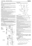
EUROSCAN TX2 / RX2 Cabin and trailer recorder INSTALLATION AND USER MANUAL EUROSCAN TX2/RX2 INSTALLATION AND USER MANUAL Table of contents 1 INTRODUCTION ............................................................................................................................... 2 1.1 Recorder versions .......................................................................................................................................................... 2 1.2 IMPORTANT: Data Security ........................................................................................................................................... 2 1.3 General description ........................................................................................................................................................ 3 2 INSTALLATION ................................................................................................................................ 5 2.1 Positioning connections ................................................................................................................................................ 5 2.2 Mounting .......................................................................................................................................................................... 6 2.3 Connectors ...................................................................................................................................................................... 8 2.4 Configuration .................................................................................................................................................................. 9 2.5 Final testing standard installation ................................................................................................................................ 9 2.6 Additional installation .................................................................................................................................................... 9 USER MENUS ................................................................................................................................... 10 1. Print menu ....................................................................................................................................................................... 10 2. Alarm menu ..................................................................................................................................................................... 11 3. User settings menu ......................................................................................................................................................... 13 4. Status menu .................................................................................................................................................................... 14 4 PARAMETER MENU ...................................................................................................................... 15 Menu 5. Temperature inputs settings .......................................................................................................................... 15 Menu 6. Digital inputs settings..................................................................................................................................... 16 Menu 7. Compartment settings .................................................................................................................................... 16 Menu 8. Alarm settings ................................................................................................................................................. 17 Menu 9. Printer settings ................................................................................................................................................ 17 Menu 10. General settings .............................................................................................................................................. 18 Menu 11. Communication settings ................................................................................................................................ 18 ATTACHMENT A TECHNICAL DATA .............................................................................................. 19 ATTACHMENT B REPLACE PAPER ROLL ..................................................................................... 20 ATTACHMENT C FACTORY SETTINGS .......................................................................................... 21 ATTACHMENT D ERROR CODES ................................................................................................... 23 EN-MAN-0041.02 Mai 15, 2014 1 of 24 EUROSCAN TX2/RX2 INSTALLATION AND USER MANUAL 1 Introduction This manual is a guideline for the installation and use of the EUROSCAN TX2/RX2 temperature recorders. To avoid guarantee exclusion due to incompetent installation it is most essential to follow the instructions and recommendations of this manual. EUROSCAN TX2 and EUROSCAN RX2 temperature recorders are developed and produced to conform to the applicable European and National guidelines for the delivery of chilled and frozen transport goods in transport vehicles. EUROSCAN TX2/RX2 can provide evidence of correct temperatures for every trip in the form of a delivery ticket, numerical or graphical print-out. All data is stored with a date/time stamp in a large flash memory. Data will not be lost if power supply is disconnected. The real time clock is powered by an internal back-up battery. The two recorder versions EUROSCAN TX2/RX2 look different. The R-Version is suitable for in cab installation and the T-Version for outside mounting on a trailer. Both versions are available with or without integrated printer. A printer can be retrofitted at any time, the recorder has been designed already in hardware and software for it. 1.1 Recorder versions 1.1.1 EUROSCAN – RX2 The R-Version has been developed for mounting in a vehicle cabin. The chassis of the recorder meets the dimensions of a DIN car radio and can be easily mounted in a free available radio slot. On the back side the connectors are designed for up to 4 temperature sensors and 4 digital inputs, a power supply, digital outputs and an RS232 connector. If no free radio slot is available, the use of the optional universal mounting kit is strongly recommended. 1.1.2 EUROSCAN – TX2 The T-Version has been developed especially for mounting outside on a body or trailer. The unit is fixed into a water proof plastic box (IP65). As on the R-version the connectors are on the back of the unit. Cabling is installed through watertight cable glands. Both products are produced by Euroscan in the EU. Euroscan has a policy of continuous development and improvements. Therefore, products, manuals and technical information are subject to change without prior notice. 1.2 IMPORTANT: Data Security Although the Euroscan X2 recorder has been specifically designed and tested for use in the harsh vehicle environment there are certain circumstances beyond our control, i.e. lightning strikes, high voltage peaks, theft, manipulation, etc., where data loss could occur. Because the temperature data might be crucial to providing evidence in the case of transport damages, we strongly advise to take the following precautions: • • Print or download data to a PC on a weekly basis as a back up. For a long-term storage of the data we recommend to down-load the data into the Euroscan EuroLOG software via one of the communication options offered by Euroscan. In addition to the infrared connection Euroscan offers a variety of communication options for automated data transfer from the recorder to the different Euroscan software options. For further information please contact the Euroscan Sales team or visit our website http://www.euroscangroup.com. EN-MAN-0041.02 Mai 15, 2014 2 of 24 EUROSCAN TX2/RX2 INSTALLATION AND USER MANUAL • • • • • Check the correct functioning of the recorder frequently (minimum – together with the fridge service). Check the recording system every 12 months to see if the measurement is within the legal error limit. The annual test is an obligation according to EN 12830 or EN 13486, respectively. Do not weld without disconnecting the power from the Euroscan recorder or the vehicle. Do not take the power supply from a generator system without extra filter protection against high voltage peaks. Preferably always take power direct from the vehicle or fridge battery. Follow the installation and user instructions in this manual. 1.3 General description The control panel of the EUROSCAN TX2/RX2 consists of three main components: 1. LCD display 2. Keyboard 3. Printer (optional) 1.3.1 LCD display The display has four lines of information, showing the following content in the operating mode. Line 1: Alarm activated; temperatures; status of digital inputs -23 –12 –08 –15 Line 2: Rotating display of each temperature to an accuracy 1:Return air –22.8 of 1 decimal point with sensor name Line 3: Day, date, and time with indication of Wednesday 21/06/2005 13:47:05 summer/wintertime Line 4: Description of the actual button functions In every other mode the content of the display is dependent on the actual menu in use. 1.3.2 Keyboard EUROSCAN TX2/RX2 are completely menu controlled. All functions can be carried out via the four coloured buttons (like printing, activate alarms or change parameters). The actual function of the buttons are always displayed on the bottom line (chapter 2). To navigate through the menus and change settings, two different kinds of button functions are applicable. To navigate through the menus and to select in the edit mode a parameter from a table, use the buttons as described below: Blue Yellow Green Red ↑ < ↓ > edit accept <-Menu <-Cncl Previous item of the menu In edit mode: Next item from the list Next item of the menu In edit mode: Previous item from the list Menu select, change to edit mode or one menu level down In edit mode: accept input and go to next menu point One menu level up In edit mode: cancel input and display the non changed value. Press 2 seconds for rejecting input and go back to previous menu. When entering free programmable text like names the button functions are as follows: Blue Yellow ↓ Green ↑ < EN-MAN-0041.02 Mai 15, 2014 Next character from the list Previous character from the list One character to the left 3 of 24 EUROSCAN TX2/RX2 INSTALLATION AND USER MANUAL Red > Blue + Yellow <-cncl Green + Red accep One character to the right Cancel input and display the non-changed value. Press for 2 seconds to reject the input and go back to the previous menu. Accept input and go to next menu point. 1.3.3 Printer (optional) The optional thermal printer is installed in the right side of the recorder. Due to the so called “Plug and Play concept” the printer can be retrofitted at any time without disconnecting the recorder from power. For retrofit, the existing mechanism will be exchanged for a mechanism with printer. To remove the printer or the housing, pull down clear plastic flap (with Euroscan logo). Printer slides forward and can be pulled out. After changing the paper please install the printer with the flap open and close the flap only after the printer is fully inserted. Note: a printout must be torn downwards over the edge of the bottom plastic part. A coloured line on the last meter of a roll indicates that the paper roll needs to be replaced (Attachment B). EN-MAN-0041.02 Mai 15, 2014 4 of 24 EUROSCAN TX2/RX2 INSTALLATION AND USER MANUAL 2 Installation In general EUROSCAN temperature recorders are supplied with all required components for a standard installation. A standard installation includes the mounting of the unit itself, mounting and connecting of two temperature sensors. Optionally 2 extra sensors and up to 4 digital (status) inputs can be connected. The main steps of the installation are described in the following chronological order. 2.1 Positioning connections 2.1.1 Temperature sensors EUROSCAN – Temperature recorders can only be used with Euroscan temperature sensors as supplied with the EUROSCAN - package. Before installation, it is necessary to determine how many measurement points are required to retrieve the desired information. Only with an optimal choice of the number and the position of the sensors can a sensible conclusion be drawn of the air temperature in an entire compartment. The following items must be observed at planning: − The temperature sensor must not be mounted in a location without air circulation. − The sensor position should be protected against bumping of load, doors, etc. − The channel of the interior light must have a minimum distance of 0.5 m to the sensors. − At least one sensor per compartment and also one sensor in the return air are recommended. The best position of a compartment sensor is in the middle under the ceiling at about 1/3 of the compartment length counted from the back. − The compartment sensor should be mounted with the Euroscan protection guard, which will allow sufficient air circulation around the sensor. Euroscan TX Temperature sensors Back door switch (P/N: DS-0201-00) 2.1.2 Digital inputs The digital inputs allow monitoring and registration of doors (open/close) or defrost and refrigeration (on/off). By configuring the parameters the interpretation of the corresponding status can be distinguished. 2.1.3 Power supply The power supply must be connected directly to the vehicle or fridge battery. The included 10A (T) floating fuse must be fitted in the +power line as close as possible to the power connection. The EUROSCAN recorders are suitable for a voltage between 10 - 36 Volt DC. EN-MAN-0041.02 Mai 15, 2014 5 of 24 EUROSCAN TX2/RX2 INSTALLATION AND USER MANUAL 2.2 Mounting The installation set of the EUROSCAN – recorder contains almost all components required for a standard installation with two temperature sensors. In addition to that some small materials like a silicon kit, PVC trunking, and fixing materials for cable mounting are required. − Preferably, use for both outside and inside walls the existing cable trunking. Alternatively, use self adhesive cable trunking. All drilled holes need to be sealed with a suitable sealant. − For future calibration requirements, it is advisable to allow enough spare cable to enable the sensor to be lowered to the floor. 2.2.1 Euroscan R-version The R-version is designed to be mounted within the cab of a vehicle in a DIN radio slot. The R-version is retained in the mounting cage by a spring locking plates fitted to each side. Fix the mounting cage by inserting it into the slot and by bending the fixing blades to secure it in the facia. Slide the recorder into the cage until it locks into position. Once fitted into the cage, the removal procedure is to insert the keys provided into the keyways at each side of the front face of the recorder to release the locks. 2.2.1.1 Optional junction box When installing more than two sensors in the case of an R-version it is recommended to use a junction box making the installation simpler. If the installation is done this way one multi-core cable connects the recorder with the junction box in which the different sensors and status inputs are connected. As pins 1, 3, 5, and 7 of the sensor inputs are linked via ground only one of these pins needs to be connected. Status inputs are pins 2, 4, 6, and 8. EN-MAN-0041.02 Mai 15, 2014 6 of 24 EUROSCAN TX2/RX2 INSTALLATION AND USER MANUAL 2.2.1.2 Optional mounting kit If no radio slot is available the recorder should be mounted with the optional mounting kit (P/N ET-1100-31). This will replace a radio slot and can be fixed either on or under the dashboard as well as on the back wall. Ensure that the position chosen allows the driver to see the display and use the operator keyboard. Please keep in mind that access to the printer is required to replace the paper roll. This requires clearance above the recorder. 2.2.2 Euroscan T-version The T-version has been designed for outside mounting directly on the body. Usually it is fixed under the refrigeration unit on the front side of the body where it is easily accessible. For fixing proceed as follows: first hold the box in the desired position and mark the mounting holes. Next step is to drill the holes so that the rubber sleeves fit in exactly and the box can be screwed on. Please make sure that the cable glands of the box show downwards. Cables should be installed via watertight cable glands. This avoids humidity penetration into the box. For each cable a separate gland should be used unless you use a gland especially designed for more cables. EN-MAN-0041.02 Mai 15, 2014 7 of 24 EUROSCAN TX2/RX2 INSTALLATION AND USER MANUAL 2.3 Connectors As both versions are provided with identical PCBs the connections for temperature sensors, digital inputs and power supply are the same for both versions. On the back of the recorder you will find four connector blocks (see picture) each of them being described in detail in the next paragraphs. 2.3.1 Connector block 1 (power supply and outputs) Power supply Connect power supply on pin 1 (+) and pin 2 (-). The recorder is suitable for a voltage between 10-36 Volt DC. Power consumption when printing is 25W. Display background light (preferable for the R-version) Usually the display background light switches on after pressing any key and switches off automatically after some seconds if no further key is pressed. If a permanent background light is required while driving connect pin 3 to a vehicle ignition +signal. (Warning: never connect directly to vehicle battery). Alarm outputs Pin 4 and 5 are digital alarm outputs, pin 4 for a temperature alarm and pin 5 for a status alarm. Both outputs switch to ground in case of an alarm situation and are limited to 1A output current. 2.3.2 Connector block 2 (serial port) The temperature recorder has two serial communication ports. These are used for a permanent connection with external devices. To be connected with a suitable connector (connector block 5-way, P/N ET-0300-15). 2.3.3 Connector block 3 (digital inputs) EUROSCAN-recorders offer the possibility to connect up to 4 digital inputs. Pins 1-8 are accordingly marked with D1-D4 (D1=Pins 1+2, ...). At every opening or closing of the input circuit a status change will be recorded into memory, but only if the input has been activated and configured correctly in the parameter settings. All four inputs as standard are de-activated, the next functions are pre-programmed: D1 = refrigeration, D2 = back door, D3 = defrost, D4 = side door. For the status inputs the polarity must be considered. Pins 2, 4, 6, and 8 are internally connected to ground. Pins 1, 3, 5, and 7 are signal inputs. 2.3.4 Connector block 4 (temperature inputs) Euroscan recorders offer the possibility to connect up to 4 temperature sensors. Pins 1-8 are accordingly marked with T1-T4 (T1 = Pins 1+2, ...). Pins 2, 4, 6, and 8 are signal inputs and pins 1, 3, 5, and 7 are internally connected to ground. The polarity of the sensor cable is not relevant. In the factory settings inputs 1 and 2 are activated and pre-programmed as follows: T1 = return air,T2 = rear. Please note that a used input always has to be activated and configured in the parameter menu. EN-MAN-0041.02 Mai 15, 2014 8 of 24 EUROSCAN TX2/RX2 INSTALLATION AND USER MANUAL 2.4 Configuration After finishing the physical installation of the temperature recorder it should now be configured. All parameters are stored in a parameter file. After every standard installation a number of parameters need to be either checked or changed. Time and date are directly accessible in the user menu, all other settings are accessible via the pin code protected parameter menu. (Factory settings see Attachment C): • • • • • Time, menu 3.1/Date, Menu 3.3 Temperature inputs, menu 5, input T1 is preset as „return air“ and input T2 as “rear”. Both inputs are also activated for recording and printing. Vehicle ID, menu 10.4 Header text, menu 10.5 Sample rate, menu 10.3 2.5 Final testing standard installation The following features must be checked after installation: Power supply The supplied power voltage is between 10V and 36V DC and protected with a 10A floating fuse. The power supply must be sufficient to offer 25W (if applicable check by printing any ticket). 2.5.1 Display/keyboard The background light of the display must switch on after pressing any key (except if using the permanent background light function) and an acoustic signal can be heard. The display shows the actual temperatures of the activated temperature inputs. 2.5.1 Temperature sensors After approximately 5 minutes the temperature must be correctly displayed. A value of -40°C indicates the possibility of a non-connected sensor or a cable failure. A value of +50°C indicates a possible short circuit between the connector pins. 2.6 Additional installation The following items are to be checked if applicable: 2.6.1 Printer Test the printer by printing any ticket. 2.6.2 Status inputs For each activated status input a small box appears in the top right hand of the display (pre-defined symbol, indicating that the corresponding input has been activated). If the status of the input changes a symbol can be chosen instead of the box. This symbol appears and disappears according to the change of the status. 2.6.3 Alarm signal The internal alarm signal (persistent buzzer) can be heard as soon as a defined temperature limit has been exceeded. In the case of an alarm an external signal is also activated if this is installed. Furthermore the corresponding temperature input will flash on the display. The internal signal buzzer can be switched off by pressing the yellow (alarm) key. The external signal and the flashing display will only stop after the temperature is back within the defined limits. EN-MAN-0041.02 Mai 15, 2014 9 of 24 EUROSCAN TX2/RX2 INSTALLATION AND USER MANUAL User menus EUROSCAN TX2/RX2 have four different user menus which are directly accessible via the keyboard: - Print menu - Alarm menu - User settings menu - Status menu 1. Print menu Delivery Ticket Current values Press blue button. The last selected print choice will be displayed. Printing starts after 2 seconds. Repeatedly pressing the blue button will scroll between the available print options: delivery ticket, journey ticket graphical, journey ticket numerical. By pressing the blue button for more than 2 seconds the following sub-menus are reached: 1.1 Select compartment to print. By pressing the green button you confirm that you wish to change the settings. The chosen compartment can be selected by pressing [↑] / [↓] and your choice can be confirmed with [edit]. 1.2 Print event report By pressing the green button [ACCEPT] printing of the event report will start. 1.1 Select compartment to print Compartment 1 ↑ ↓ EDIT <-MENU 1.2 Print report EVENTS ↑ ↓ ACCEPT <-MENU 1.3 Print parameter report By pressing the green button [ACCEPT] the parameter report will be printed after entering the correct pin code (1-2-1-2). 1.3 Print report PARAMETERS ↑ 1.4 Set print date With [EDIT] you can select a historical date for printing. After confirmation of the date with [ACCEPT] you can select the required report with the blue button. Printing starts after a delay of 2 seconds. 1.5 Delivery ticket settings With [EDIT] you can set the desired information printed on the delivery ticket. You can select “actual value”, “actual + average” or “actual, average and min-max values”. By pressing the green button you confirm your choice. EN-MAN-0041.02 Mai 15, 2014 10 of 24 ↓ ACCEPT. <-MENU 1.4 Set print date (01-01-2005) ↑ ↓ EDIT <-MENU 1.5 Delivery ticket setting ↑ ↓ EDIT <-MENU EUROSCAN TX2/RX2 INSTALLATION AND USER MANUAL 1.6 Print time period 1.6 Print time period (10 hours) With this option you define the total print period. ↑ 1.7 Day start time This option defines the time which is taken as start time for the printout (printout is done backwards till this time). ↓ EDIT <-MENU 1.7 Day start time (06:00) ↑ ↓ EDIT <-MENU 1.8 Day end time 1.8 Day end time This option defines the time from which the printout is done backwards (please note that printout is always done backwards, i.e. from the day end time till start time). (18:00) Examples: - You want to make a printout for a certain date in the past for a time period which exceeds the day start time. Please change day start time to 0:00 h and enter the desired time period. - You want to make a printout for 2 days. Please change time period to 2 days, day start time to 0:00 h and day end time to 0:00 h. 2. Alarm menu Up to four different alarm types can be allocated to up to four different compartments. The various alarms (and compartments) are only available if the supervisor has preset and configured them in the parameter menu. By pressing the yellow button you go to the alarm menu. You will get first information whether an alarm has been set for the two compartments. Alarm Comp 1 OFF Comp 2 OFF XX XX When pressing the yellow button a second time you reach the options which can be changed. With [↑] / [↓] you toggle between the compartments available. The value given in brackets shows the actual setting. By pressing [EDIT] you can change alarms for the compartment which has been chosen before. 2.1 Compartment 1 (Off) With [<] / [>] you select the desired alarm type (including alarm off). By pressing [ACCEPT] the chosen alarm will be activated. The display changes to the prior menu “Compartment 1” 2.1 Compartment 1 Frozen ↑ < EN-MAN-0041.02 Mai 15, 2014 11 of 24 ↓ > EDIT ACCPET <-MENU <-CNCL EUROSCAN TX2/RX2 INSTALLATION AND USER MANUAL In case of an alarm condition an acoustic signal will be audible and on the display the corresponding temperature input will flash. After an alarm is accepted with the yellow button the acoustic signal will stop but the alarm remains active until the temperature is again within the limits (for each compartment a separate alarm can be activated). By pressing the yellow key for more than 3 seconds you define a starting point for a dedicated journey (JOURNEY START – PRINT MARKER SET) EN-MAN-0041.02 Mai 15, 2014 12 of 24 EUROSCAN TX2/RX2 INSTALLATION AND USER MANUAL 3. User settings menu With the user settings several adjustments can be done to offer the user a maximum of user convenience. By pressing the green button the user setting menu will be activated. Toggle with [↑] / [↓] between the available menu options (3.1; 3.2; 3.3; …). Between brackets „(..)“ the actual setting is displayed. With [EDIT] you enter the edit mode in order to change the settings to your convenience. The following pictures show the display in the edit mode. 3.1 Set time (14:09:03) 3.1 Set time 3.1 Set time 14:09:23 <-cncl accept. Select hours, minutes, and seconds with [<] / [>] and adjust with [↑] / [↓]. Confirm the setting with [accept] (green-red). ↑ ↓ ↑ 3.2 Summer/Winter time correction If you do not want an automatic adjustment of summer and winter time you could define this here. EDIT ↓ <-MENU < > 3.2. Sum/Win corr. (auto adjustment) ↑ ↓ EDIT <-MENU 3.3 Set date Select date, month, and year with [<] / [>] and adjust with [↑] / [↓]. Confirm setting with [accept] (green-red). 3.3 Set date 21/06/2005 <-cncl accept ↑ 3.4 Select language Select the desired language with [<] / [>] and confirm with [accept]. ↓ Set the desired display contrast [<] / [>] and confirm with [ACCEPT]. > Set the intensity of the backlight to your convenience [<] / [>] and confirm with [ACCEPT]. The light switches on when you press any button and switches off after 30 seconds. EN-MAN-0041.02 Mai 15, 2014 13 of 24 ACCEPT <-CNCL 3.5 Set display contrast < 3.6 Set display backlight > 3.4 Select language English < 3.5 Set display contrast < > ACCEPT <-CNCL 3.6 Set display backlight < > ACCEPT <-CNCL EUROSCAN TX2/RX2 INSTALLATION AND USER MANUAL 3.7 Set keyboard backlight Set the intensity of the backlight to your convenience with [<] / [>] and confirm with [ACCEPT]. The light switches on when you press any button and switches off after 30 seconds. 3.7 Set keyboard backlight < > ACCEPT <-CNCL 3.8 Set buzzer volume Change the buzzer volume with [<] / [>] and confirm with [ACCEPT]. 3.8 Set buzzer volume < < 3.9 Set buzzer frequency Change the buzzer frequency with [<] / [>] and confirm with [ACCEPT]. > > einst. ACCEPT <-abbr <-CNCL 3.9 Set buzzer frequency < > ACCEPT <-CNCL 3.10 Set buzzer on-time Change the buzzer on-time with [<] / [>] and confirm with [ACCEPT]. 3.10 Set buzzer on-time < > ACCEPT <-CNCL 3.11 TMS Vers. V1.x Displays the actual software version of the recorder 3.11 TMS vers. V1.x © 13/12/2004 17:43 ↑ ↓ <-MENU 4. Status menu Press red button. The display mode will change between full menu information or only showing actual temperatures enlarged: T1 T3 -18.3 -21.4 3.2 T2 T4 4.1 In order to return to the main display please press either the blue, yellow or green button. EN-MAN-0041.02 Mai 15, 2014 14 of 24 EUROSCAN TX2/RX2 INSTALLATION AND USER MANUAL 4 Parameter menu The EUROSCAN TX2/RX2 recorder has been designed to enable a multiple number of desired applications for individual customers. By using the corresponding parameter settings you can adjust the recorder functionality to the required needs. This chapter gives an overview and structure of the various parameters available. To enter the parameter menu press the green button for 2 seconds. The display will show: “ENTER PINCODE” The factory setting of the pin code is 1111 but can be adjusted by the supervisor at any time (Item 10.6). Parameter Settings. ENTER PINCODE **** 1 2 3 4 After entering the correct pin code you have access to the parameter menu and the first menu level is displayed. Select the desired item with [↑], [↓] and press [EDIT] to enter one of the following options: 5. Temperature inputs settings 6. Digital inputs settings 7. Compartment settings 8. Alarm settings 9. Printer settings 10. General settings 11. Communication settings 5. Temperature inp. settings ↑ ↓ EDIT <-MENU Menu 5. Temperature inputs settings 4 inputs for temperature measurements, you can switch on/off each input and assign a name depending on the sensor position. Standard input 1 is preset as “Return air” and input 2 as “Rear”. 5.1. T1 Input >on/off If „on“ input 1 will be measured, displayed and stored into memory. Printing of input 1 is assigned in the compartment setting (menu item 7). If „off“ go to item 5.2. 5.1.1. Type >Temperature You can select a sensor type (temperature or relative humidity) 5.1.2. Name >Return air You can select a sensor name from the table or enter a 5.1.2 Name free text (free text is not translated when changing the Free Text language). <-cncl 5.1.3. Name for >free text ↑ Enter a text as desired via the four buttons 5.2. T2 input >on/off, menu structure as 5.1. 5.3. T3 input >on/off, menu structure as 5.1. 5.4. T4 input >on/off, menu structure as 5.1. EN-MAN-0041.02 Mai 15, 2014 15 of 24 ↓ accept. < > EUROSCAN TX2/RX2 INSTALLATION AND USER MANUAL Menu 6. Digital inputs settings 4 inputs for status recording, any input can be switched on/off, assigned with a name and inverted polarity. A number of names are available as a factory setting, to be selected from a list. In the operating mode you can see on the display which inputs are activated. An empty small box indicates that the input is active and the status “low”. When the status is “high”, depending on the assigned function a corresponding symbol is displayed (Refrigeration =, Defrost=, Door contact=, Other=) 6.1. Digital input 1 >on/off If „on“ every input status change on D1 will be displayed and recorded with a date/time stamp. 6.1.1. Name >Refrigeration Select a sensor name from the list or enter a free text (free text is not translated when changing the language). 6.1.3 Active >high/low Input polarity switch. Switch function if “high”: contact closed = input active. If “low”: contact open = input active (applicable for door contacts, active = open) 6.1.4 Alarm >on/off ON in order to activate alarm for this input. In this case you get the following option: 6.1.4.1 Delay time >10 minute(s) Alarm delay time given in minutes 6.2. Digit. input 2 >on/off, menu structure as 6.1 6.3. Digit. input 3 >on/off, menu structure as 6.1 6.4. Digit. input 4 >on/off, menu structure as 6.1 Menu 7. Compartment settings In this menu you have to configure the print and alarm functions for up to maximum 4 compartments. Per compartment one name can be assigned like FRONT, BACK, SIDE. The user is able to print a ticket or activate an alarm per compartment 7.1. Compartment 1 >on/off Activates or deactivates compartment 1. 7.1.1. Compart. name >compartment 1 The name for a compartment needs to be set as a free text and will not be translated when changing the language 7.1.2. Print T1 >on/off 7.1.3. Alarm on T1 >on/off 7.1.4. Print T2 >on/off 7.1.5. Alarm on T2 >on/off 7.1.6. Print T3 >on/off 7.1.7. Alarm on T3 >on/off 7.1.8. Print T4 > on/off 7.1.9. Alarm on T4 > on/off 7.1.10. Print D1 > on/off 7.1.11. Print D2 > on/off 7.1.12. Print D3 > on/off 7.1.13. Print D4 > on/off 7.2. Compartment 2 > on/off, menu structure as menu 7.1 7.3. Compartment 3 > on/off, menu structure as menu 7.1 7.4. Compartment 4 > on/off, menu structure as menu 7.1 EN-MAN-0041.02 Mai 15, 2014 16 of 24 EUROSCAN TX2/RX2 INSTALLATION AND USER MANUAL Menu 8. Alarm settings 4 groups – each with a name to assign, upper and lower temperature limit and a delay time. Each enabled alarm type can be activated by the user for any compartment, although per compartment only one alarm group can be set at the same time. 8.1. Alarm Group 1 >on/off 8.1.1. Name >Frozen You can select a preset alarm group from a list or enter a free text (free text is not translated when changing the language). 8.1.2. Upper limit >-15 °C 8.1.3. Lower limit >-30 °C 8.1.4. Delay time >45 minutes, delay time for alarm activating 8.2. Alarm Group 2 >on/off, menu structure as menu 8.1 8.3. Alarm Group 3 > on/off, menu structure as menu 8.1 8.4. Alarm Group 4 > on/off, menu structure as menu 8.1 Menu 9. Printer settings Following settings enable you to configure the printer functions as desired: 9.1. Graph upper limit >15 °C Upper limit for graphical printout 9.2. Graph lower limit >-30 °C Lower limit for graphical printout Please note: If the total temperature range between upper and lower limit can be divided by 9 you achieve an optimal result for the printout 9.3. Graph mm per hour >10 mm A graphical printout consumes a lot of paper. This parameter enables you to set the scaling of the printout (mm of paper per hour). Set a value to avoid wasting paper. 9.4. User menu >yes/no If set to „yes“the following 4 parameters will be available for the user in the print menu (see chapter 3.1 for detailed description). 9.5. Delivery ticket setting Actual only/Actual + average/Actual + average + min/max. 9.6. Print time period >10 hours Set time period (see chapter 1.6) 9.7. Day start time >06:00 Set day start time for printing (see chapter 1.7) 9.8. Day end time >18:00 Set day end time (see chapter 1.8) EN-MAN-0041.02 Mai 15, 2014 17 of 24 EUROSCAN TX2/RX2 INSTALLATION AND USER MANUAL Menu 10. General settings General settings for the unit can be entered: 10.1. Temperature unit 10.2. Date format 10.3. Sample rate °C/°F TT/MM/JJJJ >10 minute(s) The interval time in minutes (1, 2, 3,..,15, 20, 25, 30,.., 60 minutes) for storing a temperature measurement into memory 10.4. Vehicle ID >ABCDEF 16 characters are available for assigning vehicle identification. It is necessary to enter an identification like registration number or chassis number in the case of a trailer. The vehicle ID will be shown on every printout in the header together with the serial number and header text. 10.5. Header text >Abcdef 16 characters are available for assigning a header title (usually the company name). The header text will be shown on every printout. 10.6. Pin code >1111 The pin code is intended to avoid having unauthorised people access to changing parameters which can influence a correct recorder operation. Select a code between 1111 and 7777 (7 highest possible number!). The factory setting is 1111 (digit „0“ is not available). Please note: Do not forget to write down the new pin code and store it in a safe place. There is no master code available to get later access to the parameter menu. 10.7. Correct. factor (Example): Recommended: +4 / Setting: +4 10.8. Serial number >00112233 Displays the serial number of the recorder. The number will be set at factory and cannot be changed. The serial number will be on every printout. Menu 11. Communication settings - 11.1 Com 1 - setting The following options are available: No protocol Old ES protocol TMS protocol 9k6 DECT protocol GSM protocol GPRS protocol TMS protocol 38k4 Bluetooth protocol Frigoblock protocol - 11.2 Com 2 – setting The following options are available: No protocol Old ES protocol TMS protocol 9k6 GPS protocol TMS protocol 38k4 Bluetooth protocol Frigoblock protocol EN-MAN-0041.02 Mai 15, 2014 18 of 24 EUROSCAN TX2/RX2 INSTALLATION AND USER MANUAL Attachment A Technical data For technical support please contact your local supplier or: Euroscan Tel : +49-(0)228-92638-0 / Fax +49-228-92638-1 E-mail : [email protected] Bonn / Deutschland a) Technical specification: • Operating voltage: 10-36 V, protected against alternator load shedding • Power consumption: nominal value 0.6W, max. 25W (while printing) • Temperature: -20°C / +70°C (in operation), -40°C / +85°C (maximum) • Humidity: 97% relative humidity at 25°C • Memory size: 512kB, minimum 1 year with 2 sensors and logging interval 15 min. • Inputs: - 4 x temperatures for Euroscan sensors: measuring range –40°C to +50°C - 1 x digital for display background light, active >5V - 4 x digital, closed circuit • Ouptputs: - 2 x open input, switched to ground and current limited to 1A - Data ports: - Infra red for data transmission and service/parameter programming - 2 RS-232 connectors for external devices b) Ventilation: No special requirements. Euroscan recorders are designed for use in an automotive environment. c) IP rating: Euroscan TX2, trailer version for outside mounting, IP65 Euroscan RX2, cabin version for cabin mounting, IP22 d) Dimensions (W x H x D): Euroscan TX2, 245 x 202 x 110mm Euroscan RX2, 188 x 58 x 145mm e) Maintenance: Use for cleaning a moistened duster, without alcohol or other volatile cleaning products. f) Circuit protection : For protection a 10A floating fuse must be fitted in the positive (+VE) power line as close as possible to the power connection (contained in installation kit). g) Battery: Unit contains a lithium battery, please remove before discarding and dispose separately EN-MAN-0041.02 Mai 15, 2014 19 of 24 EUROSCAN TX2/RX2 INSTALLATION AND USER MANUAL Attachment B Replace paper roll A coloured line appears on the last meter of paper and indicates that the paper roll needs to be replaced. To change a paper roll please proceed as follows: − Pull down clear plastic flap (with Euroscan logo). Printer slides forward and can be pulled out. − Remove empty roll. − Put new paper roll into the printer and make sure that the paper is fed in the correct way. − After changing the paper please install the printer with the flap open and close the flap only after the printer is fully inserted. EN-MAN-0041.02 Mai 15, 2014 20 of 24 EUROSCAN TX2/RX2 INSTALLATION AND USER MANUAL Attachment C Factory settings 5. Temperature inputs ................................. Factory settings 5.1. T1 input .............................................. On 5.1.1. Type ......................................... Temperature 5.2. T2 Input .............................................. On 5.2.1. Type ......................................... Temperature 5.3. T3 Input .............................................. Off 5.4. T4 Input .............................................. Off 6. Digital inputs 6.1. D1 input.............................................. Off 6.2. D2 input.............................................. Off 6.3. D3 input.............................................. Off 6.4. D4 input.............................................. Off 7. Compartment settings 7.1. Compartment 1 .................................. On 7.1.1. Compartment name ............... Comp. 1 7.1.2. Print T1 .................................. Yes 7.1.3. Alarm on T1 ........................... Yes 7.1.4. Print T2 ................................. Yes 7.1.5. Alarm on T2 ........................... Yes 7.1.6. Print T3 ................................. No 7.1.7. Alarm on T3 ........................... No 7.1.8. Print T4 .................................. No 7.1.9. Alarm on T4 ........................... No 7.1.10. Print D1 ................................ No 7.1.11. Print D2 ................................ No 7.1.12. Print D3 ................................ No 7.1.13. Print D4 ................................ No 7.2. Compartment 2 .................................. Off 7.3. Compartment 3 .................................. Off 7.4. Compartment 4 .................................. Off 8. Alarm settings 8.1. Alarm group 1..................................... Off 8.2. Alarm group 2..................................... Off 8.3. Alarm group 3..................................... Off 8.4. Alarm group 4..................................... Off 9. Printer settings 9.1. Graph upper limit ................................ +15 °C 9.2. Graph lower limit ................................ -30 °C 9.3. Graph mm. per h. ............................... 5 mm 9.4. User menu.......................................... Yes 9.5. Delivery ticket setting ......................... Actual only 9.6. Print time period ................................. 10 hour(s) 9.7. Day start time ..................................... 00:00 9.8. Day end time ...................................... 18:00 10. General settings 10.1. Temp. unit ....................................... °C 10.2. Date format ..................................... dd/mm/yyyy 10.3. Sample rate..................................... 10 min. 10.4. Vehicle ID ....................................... AB-1234 EN-MAN-0041.02 Mai 15, 2014 21 of 24 EUROSCAN TX2/RX2 INSTALLATION AND USER MANUAL 10.5. 10.6. 10.7. 10.8. Header ............................................ Abcdef Pin code .......................................... 1111 Corr. Factor ..................................... +4 Serial number 11. Communication settings 11.1. COM 1 Settings No protocol Old ES protocol TMS protocol 9k6 DECT protocol GSM protocol GPRS protocol TMS protocol 38k4 Bluetooth protocol Frigoblock protocol COM 2 No protocol Old ES protocol TMS protocol 9k6 GPS protocol TMS protocol 38k4 Bluetooth protocol Frigoblock protocol EN-MAN-0041.02 Mai 15, 2014 22 of 24 EUROSCAN TX2/RX2 INSTALLATION AND USER MANUAL Attachment D Error codes If the display shows one of the following values: OC (I) the input is activated but no sensor is connected (ii) the sensor has an open circuit (sensor or wire failure) SC (I) the sensor has a short circuit (sensor or cable failure) EN-MAN-0041.02 Mai 15, 2014 23 of 24 EUROSCAN TX2/RX2 INSTALLATION AND USER MANUAL We ensure Quality Euroscan Group For more information please contact: Maximilianstr. 32 53111 Bonn/Germany Phone +49 (0) 228 92638-0 Fax +49 (0) 228 92638-10 [email protected] EN-MAN-0041.02 Mai 15, 2014 [email protected] www.euroscangroup.com www.euroscangroup.com 24 of 24