1
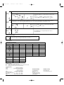
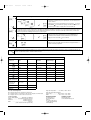
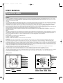
18/11/03
13:58
Side 1
U SE R M A N U A L
Type UCCG, UCDG
Installation
Please note that although fairly simple, the installation and connection of this line-voltage thermostat and the entire floor radiant heating/warming system should be
performed and checked by the qualified professional if required by your national or local building and electrical codes and ordinances.
Do not install it unless you are completely familiar and competent with house wiring. If improperly handled, there can be a risk of 120 or 240 V electric shock hazard
which may cause serious injury or death.
CAUTION!
Use only with electric radiant floor heating.Begin by turning off power to the heating circuit at the main service panel! Disconnect power supply before making wiring
connections to prevent electrical shock or equipment damage. Do NOT connect to voltage different from device rating.
This thermostat allows for either 117-120 VAC OR 230-240 VAC power supply. Which one to choose depends on what voltage your floor heating mats are. Never
mix 230-240VAC and 117-120VAC components of any electrical system unless they are ALL rated for both voltages and RADIANT HEATING MATS NEVER ARE!
Special service CO/ALR solderless connectors must be used when connecting with aluminum conductors; otherwise, a fire hazard can result.
This is NOT a typical low voltage thermostat – although designed and made with every effort to be safe, convenient to install and use this is a line voltage thermostat
and safety precaution must be taken when working with all electrical devices operating directly with house current.
If you have more than one heating mat they should be connected to the thermostat as PARALLEL CIRCUITS and NOT SERIES CIRCUITS!
Thermostat breaks heating circuit on temperature rise. Maximum load for this thermostat MUST NOT exceed 1920Watt @ 120V or 3840 Watt @ 240V otherwise a
potential fire hazard exists.
WIRING
Power supply: Provide disconnect means and the whole line overload protection as required. When using an existing wires, check the old insulation for cracks, nicks
or frying and apply certified electrical tape where necessary to achieve adequate insulation, or replace the wires in an approved manner. Maximum load for particular
circuit must not be exceeded. In many cases a dedicated circuit or line has to be used. Do not use on circuit protected by higher-rated over-current protection
devices. Some sustained fault conditions can cause product failure. All wiring must comply with applicable codes and ordinances.
Product program
This user manual covers following thermostats with built-in GFCI
UCCG-9991
Incl. floor sensor 10 ft (3m)
UCCG-9999
With built-in room sensor
UCDG-9999
With 2 sensors; built-in room sensor and incl. floor sensor 10 ft (3m)
Introduction
The thermostat is an electronic on/off thermostat for control of temperature by means of an NTC sensor either placed externally or internally in the thermostat. The
thermostat has integrated a Ground Fault Circuit Interrupter (GFCI, Class A). The thermostat and the GFCI is a dual model suitable for 120/240 V 50/60 Hz supply.
The thermostat is capable of switching on your heating system at pre determined times on different days of the week. It is possible to set 4 periods called events each
day with different temperatures. From factory a default schedule is programmed suitable for most installations. Unless you change these settings the thermostat will
operate to this default program. Working with lower temperatures during times that the room is unoccupied will lower your energy costs without reducing the comfort.
The thermostat has an adaptive function that automatically changes the start time of a heating period so that the desired temperature is reached at the time that you
set. After 5 days the adaptive function has learned when the heating must be switched on.
The thermostat type UCCG-9991 has an external temperature sensor that is normally placed in the floor construction. In this configuration the thermostat
controls the temperature of the floor and not the temperature within the room.
The thermostat type UCCG-9999 has a built-in temperature sensor. In this configuration the thermostat controls the temperature of the room.
The thermostat type UCDG-9999 has a built-in temperature sensor and an externally temperature sensor. In this configuration the thermostat
controls the temperature within the room and use the externally temperature sensor as limit sensor avoiding too high or too low temperatures in the floor construction.
The thermostat has a pin button marked R, allowing you to reset the thermostat to factory settings. These are listed at the end of this manual with space for
you to record your own weekly schedule.
1. Getting started
Display symbols
Buttons
E:
Display
®
A
Reset
I
B
GFCI
H
C
Test
G
R
D
N:
Heating on
D:
Pin button
adjust of clock
BR928A08
Lagernummer: 57558 09/03 - (BJ)
57558 09/03
F
F:
Reset to factory
setting
G:
Adjustment down
J
P
K
O
L
N
Type: UCCG, UCDG
B:
Red light
indicating
ground fault
C:
Test of GFCI
J:
Clock
function
Wake
K:
Manual
mode
Out
Home
M
I:
Adjustment up
A:
Reset of GFCI
P:
4-event
symbol:
Night
H:
OK - accept
E
O: %
Monitoring of
switch-on time
L:
M:
Time and
Day
temperature number
57558 09/03
18/11/03
13:58
Side 2
Setting the thermostat into operation
First time power is connected the clock and day will be flashing and must be set. After setting of time and day, selection of time scale (12 h or 24 h) and
temperature scale (°C or °F) can be selected. If you need to adjust the time of the thermostat at a later date, insert a pin into the hole ( ) for setting of time and
day. Adjustment must be made for summer and winter time. Setting of time and temperature scale can also be done under "advanced settings and read-out see 4.
☞
Press the UP ( ) or DOWN ( ) buttons to select
the correct time and press OK button ( ).
☞
Then press the UP ( ) or DOWN ( ) button to
select the correct day and press OK ( ) button.
☞
Press the UP ( ) button to select time and
temperature scale and press OK ( ) button.
1-7
☞
☞
☞
Checking GFCI
It is important that the GFCI has been checked for correct installation and function.
To check the GFCI: Testing can only be performed if the thermostat has a heating demand. Adjust the set point until the heating symbol (SSS) appears, use the
( ), to increase the heating demand. Wait 10 secs. to let the thermostat work according to the new set point. Press the button "TEST". The test is conclusive if
the red light on the thermostat lightens, and the display signs disappear. If this does not occur, check the installation. Press on RESET button to reset the GFCI.
The red light should disappear and the display will return to normal appearance. Push OK accept button ( ) to cancel the previously set temperature. If the test
fails, check your heating cable and the thermostat. The GFCI test should be carried out monthly.
If the GFCI trips in normal operation, without pressing the TEST button, there could be a ground fault! To check whether it is a ground fault or a nuisance
tripping, press RESET. If this cause the red light to shot off and not comes on again, it was a nuisance tripping and the system is functioning. If this cannot be
done there is a ground fault! Check your heating cable, the sensor cable and the thermostat. Exchange the defective part.
2. Daily use of the thermostat
4-event clock mode
The day has been split into 4 events describing a typical day. When the thermostat
is in 4-event mode it will automatically adjust the temperature according to the
required temperature to the required time. As standard the thermostat has 5 days
with 4 events, and 2 days with 2 events. Programming see 3.
4-event clock mode:
The clock function symbol (
Programming see 3.
Comfort mode:
☞
5 secs.
Manual mode:
☞
5 secs.
) will be indicated.
Temporary override
To temporarily override the temperature in the 4-event schedule program, press the UP ( ) or DOWN ( ) button
once, to show the temperature, and press again to increase or decrease the temperature. The display will flash for 5
seconds, and will then revert to the time. The override will operate until the next programmed event when the unit will
resume the automatic program.
Cancel comfort mode
To cancel the override state, press the OK (
☞
☞
) and one of the 4-event symbols (
) button twice.
Permanent override:
During holidays, the scheduled 4-event program can be overridden. Press the OK ( ) button, and then the UP ( )
or DOWN ( ) button until the override temperature is set. The unit will now operate to this temperature permanently.
Cancel manual mode
To cancel the permanent override state press the OK (
) button once, and the unit will resume automatic function.
57558 09/03
18/11/03
13:59
Side 3
3. Programming
4-event time and temperature
For each event, the start time and required temperature must be
set.
Press OK ( ) button for 3 secs. to begin programming
Day 1 - 5
For example, in the morning you wish the heating to start at
07:00 and the temperature to rise to 77˚F. Press OK ( ) button
for 3 seconds and the start time is displayed. Change this to
07:00 with the UP ( ) or DOWN ( ) button. Press OK ( ) to
confirm.
The temperature is now displayed. Change this to 77˚F with the
UP ( ) or DOWN ( ) button.
☞
☞
: Time and temperature
☞
☞
: Time and temperature
☞
☞
: Time and temperature
☞
☞
: Time and temperature
☞
☞
: Time and temperature
☞
☞
: Time and temperature
Press OK ( ) button to confirm. This action can now
be repeated for the second event.
These settings will be valid with days 1-5 showing on the
display. To program the days 6 and 7, repeat the above. Days 6
and 7 are usually Saturday and Sunday, and only have two
events.
Day 6 - 7
The temperature can be set within the range of +40 to +104˚F. It
is also possible to select the heating OFF at that event by
reducing the setting to 40˚F, and then pressing the ( ) once
more.
4. Advanced settings and read-out
☞
✚
☞
Press both UP ( ) and DOWN ( ) buttons together for 3 seconds. INFO is displayed.
Press UP ( ) button until you reach the desired sub menu. Select the sub menu with the OK (
Monitoring of energy consumption. The thermostat calculates average time it has been switched on allowing you to monitor your energy
consumption. In the thermostat you can read out:. Total switch-on time in percentage in the latest 2 days, 30 days or 365 days.
Calculation of operational costs per day: (switch-on time:100) x kW x kWh-price x 24 h per day
Example: Read-out: 30 % in the latest 365 days
Size of heating system: 1,2 kW (ask the installer)
Cost of power: 0,2 USD/ kWh - Calculation: (30:100) x 1,2 kW x 0,2 USD/ kWh x 24 h = 1,7 USDper day
2 days
30 days
365 days
Software version
☞
Actual sensor temperature
☞
☞
}
Press UP (
) or DOWN (
) button to show the different readouts.
No changes can be made here. Use the OK (
) button to end.
4-event sequence. The present event sequence flashes: Days 1-5, followed by days 6-7. To change, press the UP ( ) button until you
have days 1-6 and then day 7 flashing, or all 7 days are flashing. Select the required sequence with the OK ( ) button.
}
☞
☞
) button.
5-2: 4 events in 5 days +
2 events in 2 days.
6-1: 4 events in 6 days +
2 events in 1 day
7-0: 4 events in 7 days
Max and min allowed temperature range. The temperature setting range of +40˚ to 104˚ F can be limited to prevent a too high or too
low temperature being selected. For example, a wood floor covering should not be allowed to exceed a maximum of 80˚F. Low limitation
is used where the temperature of the floor is required never to fall below the minimum set temperature.
☞
Maximum allowed temperature setting. Use the UP ( ) or
DOWN ( ) button to increase or reduce, and OK ( ) button to
accept.
☞
Next is displayed LoLi. Press OK (
☞
Minimum allowed temperature setting. Use the UP (
DOWN (
) button to increase or reduce and OK (
accept.
) button to continue.
) or
) button to
57558 09/03
18/11/03
13:59
Side 4
Time and temperature scale selection
☞
☞
☞
☞
☞
}
You can select either ˚C or ˚F scale, and 12 or 24 hour clock as
follows:
Press UP (
) or DOWN ( ) button to change settings.
Confirm the required scale with the OK button (
) button.
Adaptive function: This function enables the thermostat to calculate when it needs to switch ON so that the required temperature is
reached at the set time. With a start time of 07:00 therefore, the thermostat may switch ON as early as 06:00 so that the desired
temperature of 77˚F is achieved by 07:00. Without this function set, the thermostat will start to heat at the time you set.
☞
☞
☞
}
Press the DOWN (
Press OK (
) button to switch between ON and OFF.
) button to confirm.
☞
Press OK ( ) button to end programming and to return to
scheduled program.
☞
5. Reset to factory setting
Press the pin button for 3 secs. and the thermostat returns to factory settings. Time,
day and scale for time (12h, 24h) and temperature (˚F, ˚C) read-out are also reset and
must be set according to “Setting the thermostat into operation”.
Factory settings
4-event time and temperature
Day 1-5
Time
With floor sensor
Built-in sensor
06:00
77˚F / 25˚C
68˚F / 20˚C
08:00
68˚F / 20˚C
59˚F / 15˚C
16:00
81˚F / 27˚C
72˚F / 22˚C
22:30
68˚F / 20˚C
59˚F / 15˚C
08:00
81˚F / 27˚C
72˚F / 22˚C
23:00
68˚F / 20˚C
59˚F / 15˚C
Day 6-7
4-event sequence
5:2
Hi-Low temp.
131˚F / 41˚F
Scale
24 H / ˚F
Adaptive control
ON
6. Failure codes
E0 = Internal failure, replace thermostat
E1 = Built-in sensor short-circuit or disconnected, replace thermostat
E2 = External sensor short-circuit or disconnected
7. Technical data
Supply: . . . . . . . . . . . . . . . . . . 120/240 Vac 50/60 Hz
Load:
. . . . . . . . . . . . 16A maximum (resistive load)
Power: . . . . . . . . . . . . . . . . . . . . 1.920 W at 120 Vac
3.840 W at 240 Vac
GFCI: . . . . . . . . . . . . . . . . . Class A (5 mA trip level)
Temperature range: . . . . +5 to +40°C, +40 to +104˚F
Amb. Temperature range:
Thermostat: . . . . . . . . . . . 0 to +40°C, +32 to +104˚F
GFCI:
. . . . . . . . . . . . . -35 to +65°C, -31 to +149˚F
ELEKTRA TRADING
ul. Marynarska 14
02-674 Warszawa
Poland
Tel. (+48 22) 843 32 82
e-mail: [email protected]
www.elektra.pl
SERVICE (US/CAN)
Ideal Heating LLC
[email protected]
57558 09/03
18/11/03
13:59
Side 5
Français
Installation
Please note that although fairly simple, the installation and connection of this line-voltage thermostat and the entire floor radiant heating/warming system should be
performed and checked by the qualified professional if required by your national or local building and electrical codes and ordinances.
Do not install it unless you are completely familiar and competent with house wiring. If improperly handled, there can be a risk of 120 or 240 V electric shock hazard
which may cause serious injury or death.
CAUTION!
Use only with electric radiant floor heating.Begin by turning off power to the heating circuit at the main service panel! Disconnect power supply before making wiring
connections to prevent electrical shock or equipment damage. Do NOT connect to voltage different from device rating.
This thermostat allows for either 117-120 VAC OR 230-240 VAC power supply. Which one to choose depends on what voltage your floor heating mats are. Never
mix 230-240VAC and 117-120VAC components of any electrical system unless they are ALL rated for both voltages and RADIANT HEATING MATS NEVER ARE!
Special service CO/ALR solderless connectors must be used when connecting with aluminum conductors; otherwise, a fire hazard can result.
This is NOT a typical low voltage thermostat – although designed and made with every effort to be safe, convenient to install and use this is a line voltage thermostat
and safety precaution must be taken when working with all electrical devices operating directly with house current.
If you have more than one heating mat they should be connected to the thermostat as PARALLEL CIRCUITS and NOT SERIES CIRCUITS!
Thermostat breaks heating circuit on temperature rise. Maximum load for this thermostat MUST NOT exceed 1920Watt @ 120V or 3840 Watt @ 240V otherwise a
potential fire hazard exists.
WIRING
Power supply: Provide disconnect means and the whole line overload protection as required. When using an existing wires, check the old insulation for cracks, nicks
or frying and apply certified electrical tape where necessary to achieve adequate insulation, or replace the wires in an approved manner. Maximum load for particular
circuit must not be exceeded. In many cases a dedicated circuit or line has to be used. Do not use on circuit protected by higher-rated over-current protection
devices. Some sustained fault conditions can cause product failure. All wiring must comply with applicable codes and ordinances.
Programmation du produit
Ce guide d'utilisation contient des renseignements sur les modèles de thermostat avec disjoncteur de fuite à la terre intégré.
UCCG-9991 avec capteur de plancher 10 ft (3 m)
UCCG-9999 avec capteur de pièce
UCDG-9999 avec deux capteurs; un capteur de pièce et un capteur de plancher 10 ft (3 m)
Introduction
Le thermostat est du type électronique à action par tout ou rien qui régule la température au moyen d'un capteur NTC placé soit à l'extérieur, soit à l'intérieur du
thermostat. Il est doté d'un disjoncteur de fuite à la terre (GFCI de classe A). Le thermostat et le GFCI sont compatibles aux modes d'alimentation 120/240 V 50/60 Hz.
Le thermostat peut activer le système de chauffage à des heures prédéterminées pour des jours différents de la semaine. Il est possible de régler quatre
périodes (appelées événements) à des températures différentes chaque jour. Un horaire par défaut, qui convient à la plupart des installations, a été programmé
en usine. À moins que vous ne modifiiez ces réglages, le thermostat fonctionnera selon ce programme par défaut. Si vous réglez le chauffage à une température
plus basse lorsque la pièce est inoccupée, vous couperez les coûts d'énergie sans réduire le confort. Le thermostat est muni d'une fonction adaptative qui
modifie automatiquement l'heure de début de la période de chauffage afin que la température désirée soit atteinte à l'heure que vous avez réglée. Après cinq
jours, la fonction adaptative sait quand activer le système de chauffage.
Le modèle de thermostat UCCG-9991 est muni d'un capteur de température externe que l'on place normalement dans le plancher. De cette façon, le thermostat
contrôle la température du plancher et non celle de la pièce.
Le modèle de thermostat UCCG-9999 est doté d'un capteur de température intégré. Dans cette configuration, le thermostat contrôle la température de la pièce.
Le modèle de thermostat UCDG-9999 est doté d'un capteur de température intégré et d'un capteur de température externe. Dans cette configuration, le
thermostat contrôle la température à l'intérieur de la pièce et utilise le capteur de température externe comme une sonde de limite pour empêcher que la
température du plancher ne soit trop élevée ou trop faible.
Le thermostat dispose d'un bouton miniature identifié d'un R qui vous permet de le réinitialiser aux réglages de l'usine. Ces réglages sont énumérés à la fin de
ce guide. Il y a aussi de l'espace afin que vous puissiez prendre en note votre propre horaire hebdomadaire.
1. Début
Symboles de l'affichage
Touches
BR928A08
E:
Affichage
®
A
I
Reset
B
GFCI
H
C
Test
G
R
D
N:
Chauffage en circuit
D:
Bouton miniature pour le
réglage de l’horloge
F
F:
Remise aux réglages
effectués en usine
G:
Ajustement vers le bas
J
P
K
O
L
N
B:
Voyant rouge
indicateur de
mise à la masse
défectueuse
C:
Vérification
du disjoncteur
de fuite à la
terre
J:
Fonction
d’horloge
Éveil
K:
Mode
Manual
Hors de la maison
À la maison
M
I:
Ajustement vers le haut
A:
Réinitialisation
du disjoncteur
de fuite à la
terre
P:
Symboles des quatre
événements:
Nuit
H:
OK - acceptation
E
O:
Pourcentage de
temps en circuit
L:
M:
Heure et
Numéro
température de jour
57558 09/03
18/11/03
13:59
Side 6
Activation du thermostat
À la première mise en alimentation, l'heure et le jour clignoteront et il faudra les régler. Après avoir réglé l'heure et la date, il est possible de sélectionner le
mode d'affichage des heures (12 ou 24 heures) et l'échelle de température (°C ou °F). Si vous devez ultérieurement régler l'heure du thermostat, insérez un
objet pointu dans l'orifice ( ) pour régler l'heure et le jour de nouveau. Il faut aussi ajuster le thermostat en fonction de l'heure d'hiver et de l'heure d'été. On
peut également régler le mode d'affichage des heures et l'échelle de température dans les réglages avancés (voir la section 4).
☞
Appuyez sur les touches de défilement vers le haut (UP
régler l'heure, puis appuyez sur la touche OK ( ).
) ou vers le bas (DOWN
) pour
☞
Appuyez sur les touches de défilement vers le haut (UP
régler le jour, puis appuyez sur la touche OK ( ).
) ou vers le bas (DOWN
) pour
☞
Appuyez sur la touche de défilement vers le haut
(UP ) pour régler le mode d'affichage des heures et l'échelle de température, puis
appuyez sur la touche OK ( ).
1-7
☞
☞
☞
Vérification du disjoncteur de fuite à la terre (GFCI)
Il est important de vérifier l'installation et le fonctionnement du disjoncteur de fuite à la terre.
Test du disjoncteur: Pour vérifier le fonctionnement du disjoncteur, il faut qu'il y ait une demande de chauffage au thermostat. Réglez la demande de chauffage
au thermostat jusqu'à ce que le symbole (SSS) s'affiche. Servez-vous de la touche ( ) pour augmenter la demande. Patientez dix secondes pour laisser le
thermostat s'adapter à la nouvelle demande, puis appuyez sur la touche TEST. Le test est concluant si le voyant rouge du thermostat s'allume et que les signes
sur l'affichage disparaissent. Dans le cas contraire, vérifiez l'installation. Appuyez sur la touche RESET pour réinitialiser le disjoncteur de fuite à la terre. Le
voyant rouge devrait s'éteindre et l'affichage revenir à la normale. Appuyez sur la touche d'acceptation ( ) pour annuler le réglage de température précédent. Si
le test échoue, vérifiez le câble chauffant et le thermostat. Le test du disjoncteur de fuite à la terre devrait être effectué mensuellement.
Si le disjoncteur se déclenche en mode de fonctionnement normal, sans qu'il soit nécessaire d'appuyer sur la touche TEST, cela pourrait indiquer la présence
d'une mise à la masse défectueuse. Pour vérifier s'il s'agit d'une mise à la masse défectueuse ou d'un déclenchement intempestif, appuyez sur la touche de
réinitialisation (RESET). Si le voyant rouge s'éteint et qu'il ne se rallume pas, il s'agissait d'un déclenchement intempestif et le système fonctionne correctement.
Dans le cas contraire, il y a effectivement une mise à la masse défectueuse ! Vérifiez le câble chauffant, le câble du capteur et le thermostat, puis remplacez la
pièce défectueuse.
2. Usage quotidien du thermostat
Mode d'horaire divisé en quatre événements
Le jour type a été divisé en quatre événements. Lorsque le thermostat est en mode
de quatre événements, il règle automatiquement la température de la pièce requise à
l'heure établie. Le thermostat de série commande quatre événements par jour sur
une période de cinq jours, et deux événements par jour sur une période de deux
jours.
Voir en page 3 pour la programmation.
Mode d’horaire divisé en
quatre événements:
Mode confort
☞
5s
☞
☞
) s'afficheront.
Fonctionnement prioritaire temporaire: Pour contourner temporairement le réglage de température du
programme en quatre événements, appuyez sur les touches de défilement vers le haut (UP ) ou vers le bas
(DOWN ) pour afficher la température, et appuyez sur les touches de nouveau pour augmenter ou réduire la
température. L'affichage clignotera pendant cinq secondes, puis reviendra au mode d'affichage de l'heure. Le
réglage de température prioritaire subsistera jusqu'à l'activation du prochain événement automatique programmé.
Annulation du mode confort: Pour annuler l'état prioritaire, appuyez sur la touche OK ( ) à deux reprises.
Mode manuel:
☞
Le symbole de l'horloge ( ) et un des quatre symboles d'événement (
Voir en page 3 pour la programmation.
5s
Fonctionnement prioritaire permanent: Durant les congés, par exemple, il est possible de contourner l'horaire
du programme en quatre événements. Appuyez sur la touche OK ( ), puis sur les touches de défilement vers le
haut (UP ) ou vers le bas (DOWN ) pour régler la température désirée. L'appareil maintiendra la température de
la pièce à ce niveau de façon permanente.
Annulation du mode manuel: Pour annuler l'état prioritaire permanent, appuyez sur la touche OK ( ) une fois et
l'appareil reprendra la programmation automatique.
57558 09/03
18/11/03
14:00
Side 7
3. Programmation
Heure et température des quatre événements
Pour chaque événement, il faut régler l'heure de début de
la période de chauffage et la température.
Appuyez sur la touche OK (
Vous pourriez par exemple désirer que le chauffage
commence à 7 h dans la matinée et que la température
s'élève à 77 °F. Appuyez sur la touche OK ( ) pendant
trois secondes pour afficher l'heure de début de la période
de chauffage. Réglez l'heure à 7 h à l'aide des touches de
défilement vers le haut (UP ) ou vers le bas (DOWN ) .
Appuyez sur la touche OK ( ) pour confirmer.
La température s'affiche. Réglez-la à 77 °F à l'aide des
touches de défilement vers le haut (UP ) ou vers le bas
(DOWN ). Appuyez sur la touche OK ( ) pour confirmer.
Répétez ces étapes pour le deuxième événement.
Ces réglages sont valides pour les jours 1 à 5 qui sont
affichés. Répétez les étapes ci-dessus pour programmer
les jours 6 et 7. Il n'y a que deux événements pour les
jours 6 et 7, qui sont habituellement le samedi et le
dimanche.
) pendant trois secondes pour commencer la programmation
Jours 1 à 5
☞
☞
: Heure et température
☞
☞
: Heure et température
☞
☞
: Heure et température
☞
☞
: Heure et température
☞
☞
: Heure et température
☞
☞
: Heure et température
Jours 6 à 7
La plage de température est réglable de +40 °C à +104 °C.
Il est également possible de mettre le chauffage hors
circuit pour cet événement en réduisant la température à
40°F et en appuyant sur la touche ( ) à nouveau.
4. Réglages avancés et lectures
☞
✚
☞
Appuyez simultanément sur les touches de défilement vers le haut (UP ) et vers le bas (DOWN ) pendant trois secondes. L'afficheur
montre « INFO ».Appuyez sur la touche de défilement vers le haut (UP ( ) jusqu'au sous-menu recherché. Sélectionnez le sous-menu en
appuyant sur la touche OK ( ).
Surveillance de la consommation d'énergie.
Le thermostat calcule son temps moyen de fonctionnement afin de vous permettre de surveiller la consommation d'énergie.
Vous pouvez prendre les lectures suivantes du thermostat : Temps total en circuit, en pourcentage, durant les 2, 30 ou 365 derniers jours.
Calcul des coûts d'exploitation par jour : (temps en circuit/100) x kW x coût du kWh x 24 h par jour
Exemple: Lecture : 30 % au cours des 365 derniers jours. Puissance du système de chauffage : 1,2 kW (demandez à l'installateur)
Coût de l'électricité : 0,20 $US/kWh. Calcul : (30 %) x 1,2 kW x 0,20 $US/kWh x 24 h = 1,73 $US par jour
2 jours
30 jours
365 jours
Version du logiciel
☞
Température réelle du capteur
☞
Séquence en quatre événement. La séquence d'événements en cours clignote : les jours 1 à 5 d'abord, puis les jours 6 et 7. Pour la
modifier, appuyez sur la touche de défilement vers le haut (UP ) jusqu'à ce que les jours 1 à 6 clignotent, puis le jour 7, ou jusqu'à ce que
tous les sept jours clignotent. Sélectionnez la séquence désirée en appuyant sur la touche OK ( ).
}
☞
☞
5-2: 4 événements en 5 jours +
2 événements en 2 jours.
6-1: 4 événements en 6 jours +
2 événements en 1 jour
7-0: 4 événements en 7 jours
Maximum et minimum permis de la plage de température. On peut limiter la plage de température, réglable de +40°C à 104°F, afin de prévenir
le réglage d'une température trop élevée ou trop basse. Par exemple, la température d'un revêtement de plancher de bois ne devrait pas dépasser
80°F. La limite de température basse sert aux endroits où la température d'un plancher ne doit pas tomber sous la température minimum réglée.
☞
☞
☞
}
Appuyez sur les touches de défilement vers le haut (UP ) ou
vers le bas (DOWN ) pour afficher les différentes
lectures.
Vous ne pouvez effectuer aucun changement ici. Appuyez sur la
touche OK ( ) pour quitter.
☞
Réglage de la limite de température élevée permise. Utilisez les
touches de défilement vers le haut (UP ) ou vers le bas (DOWN )
pour augmenter ou réduire la température, puis appuyez sur la touche
OK ( ) pour confirmer.
L'afficheur montre « LoLi ». Appuyez sur la touche OK ( ) pour
continuer.
Réglage de la limite de température basse permise. Utilisez les
touches de défilement vers le haut (UP ) ou vers le bas (DOWN )
pour augmenter ou réduire la température, puis appuyez sur la touche
OK ( ) pour confirmer.
57558 09/03
18/11/03
14:00
Side 8
Sélection du mode d'affichage des heures et de l'échelle de température
☞
☞
☞
☞
☞
}
Vous pouvez choisir d'afficher la température en degrés Celsius ou
Fahrenheit et de diviser le jour en périodes de 12 ou 24 heures de la
façon suivante :
Appuyez sur les touches de défilement vers le haut (UP ) ou vers le
bas (DOWN ) pour modifier les réglages. Confirmez l'échelle ou la
division du jour requise en appuyant sur la touche OK ( ).
Fonction adaptative. Cette fonction permet au thermostat de calculer à quel moment il doit se mettre en circuit pour que la pièce soit à la
température requise à l'heure réglée. Donc, si le début de la période de chauffage est réglée à 7 h, il se peut que le thermostat se mette en
circuit aussi tôt que 6 h afin que la pièce soit à la température requise de 77°F à 7 h. Si vous n'activez pas cette fonction, le thermostat
lancera le système de chauffage à l'heure que vous avez réglée.
☞
☞
☞
}
Appuyez sur la touche de défilement vers le bas (DOWN ) pour
commuter entre l'activation et la désactivation de cette fonction.
Appuyez sur la touche OK ( ) pour confirmer.
☞
Appuyez sur la touche OK ( ) pour mettre fin à la programmation et
revenir à l'horaire programmé.
☞
5. Remise aux réglages effectués en usine
Appuyez sur le bouton miniature pendant trois secondes et le thermostat reviendra aux réglages effectués en usine. Les paramètres d'heure, de
jour, d'affichage des heures (12 ou 24 heures) et d'échelle de température (°F ou °C) sont aussi réinitialisés et doivent être réglés de nouveau
comme c'est décrit à la section « Activation du thermostat ».
Réglage en usine
Heure et température des quatre événements
Jours 1 à 5
Heure
Avec capteur de
plancher
Capteur intégré
06:00
77˚F / 25˚C
68˚F / 20˚C
08:00
68˚F / 20˚C
59˚F / 15˚C
16:00
81˚F / 27˚C
72˚F / 22˚C
22:30
68˚F / 20˚C
59˚F / 15˚C
08:00
81˚F / 27˚C
72˚F / 22˚C
23:00
68˚F / 20˚C
59˚F / 15
Jours 6 et 7
Séquence en
5:2
quatre événements
Limites supérieure
et inféreure de
131˚F / 41˚F
température
Échelle
24 H / ˚F
Commande
adaptative
En circuit
6. Codes de dérangement
E0 = Défectuosité interne; remplacez le thermostat
E1 = Capteur interne court-circuité ou déconnecté; remplacez le thermostat
E2 = Capteur externe court-circuité ou déconnecté
Plage de témperature . . . . +5 à +40°C, +40 to +104˚F
Plage de témperature ambiante:
Thermostat: . . . . . . . . . . de 0 à +40°C, +32 à +104˚F
GFCI: . . . . . . . . . . . . . . . -35 à +65°C, -31 à +149˚F
7. Fiche technique
Source d’alimentation . . . . . . 120/240 V c.a.50/60 Hz
Charge . . . . . . . . . . 16A maximum (charge résistive)
Puissance . . . . . . . . . . . . . . . . . 1.920 W à 120 V c.a.
3.840 W à 240 V c.a.
GFCI:
. . . . . . . . . . . . . . . . . . . . . . . . . . . . Classe A
(seuil e déclenchement réglé à 5 mA)
ELEKTRA TRADING
ul. Marynarska 14
02-674 Warszawa
Poland
Tel. (+48 22) 843 32 82
e-mail: [email protected]
www.elektra.pl
SERVICE (US/CAN)
Ideal Heating LLC
[email protected]