1
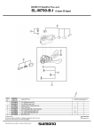
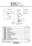
DELTA POWER SYSTEM
User manual
ES48/22-HFT Series
System IOM
ES48/22-HFT00 IOM
2010. 08. 12. R01.
P/N: 5011294201
TABLE OF CONTENTS
1
1.1
1.2
1.3
2
2.1
2.2
2.3
2.4
2.5
3
3.1
3.2
3.3
3.4
3.5
3.6
3.7
3.8
3.9
4
4.1
4.2
4.3
4.4
4.5
4.6
5
5.1
5.2
5.3
5.4
5.5
6
6.1
6.2
6.3
7
7.1
7.2
GENERAL ........................................................................................................................................ 4
USING THIS MANUAL................................................................................................................................4
SAFETY NOTICE ........................................................................................................................................4
ENVIRONMENTAL ......................................................................................................................................5
PRODUCT DESCRIPTION.............................................................................................................. 6
PRODUCT DESCRIPTION ............................................................................................................................6
PRODUCT MAIN FEATURES .......................................................................................................................6
CONFIGURATION .......................................................................................................................................6
SYSTEM GENERAL SPECIFICATION ...........................................................................................................7
SYSTEM OUTLOOK & DIMENSIONS ..........................................................................................................8
INSTALLATION................................................................................................................................ 9
TOOLS REQUIRED......................................................................................................................................9
PRELIMINARY INSPECTION........................................................................................................................9
SYSTEM MOUNTING ..................................................................................................................................9
MODULE INSTALLATION ...........................................................................................................................9
SYSTEM WIRING .....................................................................................................................................10
AC INPUT CONNECTIONS ........................................................................................................................10
DC DISTRIBUTION CONNECTIONS ..........................................................................................................11
BATTERY STRING CONNECTIONS ...........................................................................................................11
THE BATTERY TEMPERATURE SENSORS .................................................................................................12
START - UP PROCEDURE ........................................................................................................... 13
INITIAL STARTUP PREPARATION .............................................................................................................13
NO LOAD START-UP ................................................................................................................................13
BASIC FUNCTIONAL VERIFICATION ........................................................................................................13
PARAMETER SETTINGS............................................................................................................................13
DC LOAD CONNECTIONS ........................................................................................................................14
FUNCTIONALITY CHECK .........................................................................................................................14
CSU & PARAMETER ADJUSTMENT ........................................................................................... 15
DESCRIPTION...........................................................................................................................................15
INTERFACE ..............................................................................................................................................16
FUNCTION ...............................................................................................................................................17
PARAMETER SETTING .............................................................................................................................18
USER INSTRUCTION .................................................................................................................................19
RECTIFIER..................................................................................................................................... 30
DESCRIPTION...........................................................................................................................................30
SPECIFICATIONS ......................................................................................................................................30
OUTLINE & DIMENSIONS ........................................................................................................................32
DC DISTRIBUTION CABINET....................................................................................................... 33
DISTRIBUTION .........................................................................................................................................33
LVDS (LOW VOLTAGE DISCONNECT SWITCH)........................................................................................33
ES48/22-HFT00
IOM
Page: 2 of 38
7.3
8
8.1
8.2
8.3
8.4
8.5
9
9.1
9.2
9.3
BATTERY CONNECTIONS ........................................................................................................................33
ALARMS AND TROUBLE SHOOTING ......................................................................................... 34
MAIN FAIL DESCRIPTION ........................................................................................................................34
DC OUTPUT VOLTAGE HIGH/LOW (HV/LV)..........................................................................................34
DC CIRCUIT BREAKER/FUSE TRIPPED ALARM .......................................................................................34
BATTERY TEMPERATURE FAIL ALARM ..................................................................................................35
RECTIFIER FAIL ALARM ..........................................................................................................................35
MAINTENANCE ............................................................................................................................. 36
CLEANING AND MAINTENANCE ..............................................................................................................36
REMOVING AND REPLACING A RECTIFIER MODULE ..............................................................................36
ENVIRONMENT REQUIREMENT FOR WEB:..............................................................................................37
ES48/22-HFT00
IOM
Page: 3 of 38
1
GENERAL
1.1
Using This Manual
This manual contains specifications and instructions to properly install and maintain the
power system. Component specifications and drawings are contained in this manual.
Included in this manual is the operation and maintenance of the Alarm Control Unit
(ACU), DPR-600 Switch Mode Rectifier (SMR), DC Distribution Shelf, and Low Voltage
Disconnect Switch (LVDS), system status and alarms, troubleshooting and system
maintenance.
Step by step procedures required for installation and turn-up are detailed. All equipment
parameter settings, adjustments and confirmation as well as system monitoring,
operations and maintenance procedures are included.
Warnings are printed in bold lettering and alert the installation or maintenance
craftsperson of a potential hazard to either or the craftsperson if the warning advisement
is not followed.
1.2
Safety Notice
Products are not liable for any hazards incurred by not following proper safety
procedures. Installation, Operation and maintenance personnel should always follow
these safety rules:
1. Caution - Do not install or remove any SMR with the AC Breaker On. The AC
Breakers must be switched to the off position prior to inserting a module into a shelf.
2. Before the shelf is operational, the AC input frequency and voltage must be verified,
AC break rating and type is adequate, and other environmental conditions as noted in
the specifications are met.
3. The shelf has passed stringent system testing prior to shipment. To avoid electrical
shock, the DPR-600 shelf requires a single ground point permanently connected to
earth ground.
4. An AC Breaker must provide adequate isolation between the shelf input and
Commercial AC Main.
5. The environment should be dust free and controlled by an air condition system. The
area must be free of any flammable vapors or fluids.
6. To avoid electrical hazard, the covers must not be removed on any component
including the ACU and Rectifier.
7. Circuit breakers must be replaced with approved replacement circuit breakers
meeting the original design specification.
8. All AC connections must be made per the latest issue of the National Electrical Code
and must also conform to all local codes.
9. For ventilation and maintenance purpose, remain enough space when installation.
Recommended space:
Front: 12 inch
ES48/22-HFT00
IOM
Page: 4 of 38
Rear: 12 inch
1.3
Environmental
1. Input Voltage: 220V, single phase 3 wires
2. Input Frequency: 50/60 Hz ±5%
3. Operating Temperature: -25°C~+65°C (-13°F~+149°F)
-25°C~+55°C: 100% Load Output
55°C~+65°C: De-rating, 100%~70% Load Output
4. Humidity: 10 ~ 95% RH (non-Condensing)
5. Floor Load Density: 600 Kg/M2
ES48/22-HFT00
IOM
Page: 5 of 38
2
PRODUCT DESCRIPTION
2.1
Product Description
The DPR-600 Power shelf consists of modular DPR-600 rectifiers, a Alarm Control Unit
(ACU) and a DC Distribution shelf. Up to 2 rectifiers can be equipped in a shelf (22A),
which can mount an ACU. The shelf requires a nominal input of 220 Vac (single phase)
and provide an output of -54 VDC to power the load and also maintain fully charged
batteries.
2.2
2.3
Product Main Features
•
-54 VDC/22A Output
•
Hot Swappable 600 Watts rectifiers, wide range PFC input (90~275Vac good for
unstable utility environment)
•
Light Weight Plug-in Modules for Simple Installation and Maintenance
•
High Power Density Saves Valuable Floor space
•
All rectifier modules are front accessible
•
Active Power Factor Correction (> .99 PF)
•
High efficiency, > 91.5%
•
Temperature compensation float voltage control for VRLA batteries from Control
Supervisory Unit 502 LCD version (CSU502+)
•
Front Access for Simplified Operation and Maintenance
•
Intelligent Remote Monitoring and Control (Remote Monitoring System) for
Centralized
•
Battery temperature compensation voltage control
•
Battery and Load breakers
•
Equalize charge timer
•
Safety: CE mark
Configuration
ES48/22-HFT00
IOM
AC Input:
220V, single phase 3 wires
System Capacity:
-54VDC/22A Max.
Rectifier:
-54/600W * 2 Max.
ACU :
Delta Alarm Control Unit (ACU)
Page: 6 of 38
2.4
System General Specification
Item
Specification/Function
AC Input
220V, Single Phase
System Capacity
vs
AC Input
1,200W @ 185~276Vac
System Capacity
vs
Operating Temperature
1,200W @ -20~65°C
Rectifier (54V/11A)
600W / fixed
Shelf (54V/22A)
600W x 2 fixed
Communication
Analogue for each rectifier and control unit
Operating Temperature
-25°C~+65°C (-13°F~+149°F)
Storage Temperature
-25°C ~+65°C (-13°F~+149°F)
Humidity
0~95% Relative Humidity, Non-Condensing
Altitude
< 4000m above mean sea level
2000 m - 3000 m:
1% power derating per 100m. At 3000m altitude, the output
power can be 90% of the nominal power rating at maximum
temperature.
3000 m - 4000 m:
2% power derating per 100m. At 4000m altitude, the output
power can be 70% of the nominal power rating at maximum
temperature.
Acoustic
55 dB @ 1 meter, Ambient temperature 25°C at full load
ES48/22-HFT00
IOM
(with 2 rectifiers @ -25~65°C)
(with 2 rectifiers @ 185~276Vac)
Page: 7 of 38
2.5
System Outlook & Dimensions
Item
Shelf Dimensions (WxDxH)
ES48/22-HFT00
IOM
Specification/Function
433 x 296.6 x 44 mm /17.04 x11.7 x1.73inch
Page: 8 of 38
3
INSTALLATION
3.1
Tools Required
The following tools are recommended for the DPR-600 installation:
3.2
•
Phillips No. 3 screw driver
•
Insulated slotted screw driver - blade size 1/4”
•
Insulated slotted screw driver - blade size 1/8”
•
Tweaker - Slotted screw driver blade size .09”× .02”
•
Insulated side cutters
•
Metric Socket Wrenches with Extensions
Preliminary Inspection
Prior to removing the system from the crate, note any damage to the crate. Remove the
shelf from the crate and inspect the shelf for any dents or damage. If any damage is
noted, contact the carrier immediately.
3.3
System Mounting
The shelf comes fully assembled with the DC Distribution Shelf, rectifiers mounted in a
19” shelf. The AC connections from the AC switch to the rectifier shelf are made at the
factory. All CSU communication and signal leads are connected via the modular plugs
and communicate with the rectifiers.
Mount the shelf with a distance no less than 12 inches from the rear of the rectifier shelf
to a wall. This will provide adequate ventilation for the rectifiers. The front of the shelf
should be clear of all obstruction and allow room for proper ventilation, installation and
maintenance. The shelf should be mounted to the superstructure and floor per
customer provided equipment engineering drawings.
3.4
Module Installation
In order to minimize the weight of system, all rectifier modules can be removed from the
shelf and re-installed.
3.4.1
Rectifier Installation
1) Install the rectifier modules into the shelf
Warning! Do not force the module into the slot. If it does not slide in and connect
easily, remove and re-seat the unit.
2) Push the locker to lock position to lock the rectifier.
ES48/22-HFT00
IOM
Page: 9 of 38
3.5
System Wiring
The shelf comes fully assembled and all the connections are made at the factory. There
is no internal, shelf or module wiring required.
3.5.1
Wiring Tooling & Method
3.5.1.1 AC Input
1. Use a screw driver (Φ3mm, - type) to release the screw inside the terminal.
2. Push the stripped wire (AWG# 22 – 12) into the terminal.
3. Rotate the screw to tight the wire.
4. Try to pull out the wire to check whether the wire is connecting tight or not.
Stripping length: 11 – 13mm
3.5.1.2 DC Output and Battery
1. Push the screw driver (Φ3mm, - type) into the top hole (square hole) and push
upward to release the wire clamper..
2. Push the stripped wire (AWG# 10) into the terminal.
3. Pull out the screw driver to tight the wire.
4. Try to pull out the wire to check whether the wire is connecting tight or not.
Stripping length: 9 – 11mm
3.5.2
Schematics
Refer to the system schematics P/N: 50122094xx
3.6
AC Input Connections
All the AC cables can be connected to the AC terminal on the rear of the shelf.
Recommended wire: AWG #18-20
Warning! The shelf operates at AC voltages that can produce fatal electrical shock.
Installation and maintenance personnel must observe all safety precautions.
Warning! Confirm the operating voltage before proceeding.
ES48/22-HFT00
IOM
Page: 10 of 38
Warning! The input feeder circuit breaker at the AC panel must be in the Off position
before attempting to wire the shelf.
3.7
DC Distribution Connections
Load Fuse: Car fuse size max. 6 positions (max. 15A for each position)
Recommended Wire: AWG#16
3.8
Battery String Connections
Battery Fuse: Car fuse size max. 2 positions (max. 30A for each position)
Recommended Wire: AWG#10-12
Warning! Verify the polarity of the battery leads prior to connecting the battery cables
to the system. Failure to connect the battery cables correctly to the system
can cause damage to batteries and the shelf.
ES48/22-HFT00
IOM
Page: 11 of 38
3.9
The Battery Temperature Sensors
One battery sensor cable is provided with each shelf. The cable is labeled TB terminate
on connector TB on the Detection Module. The positive bus on the inter-cell connections
of the battery strings for -54 VDC, or in between the battery cells depending on whether
the batteries are exiting or being installed with the power shelf.
ES48/22-HFT00
IOM
Page: 12 of 38
4
START - UP PROCEDURE
4.1
Initial Startup Preparation
Verify all connections prior to starting this section.
Warning! Ensure the input AC circuit breaker located at the AC service panel is
switched to the “Off” position.
Warning! Confirm the operating voltage before proceeding.
Warning! Ensure the frame ground is properly connected to a permanent earth ground
connection.
Warning! Ensure all the Load DC Circuit breakers located in the DC Distribution
Cabinet are switched to the “Off” position.
4.2
No Load Start-up
The shelf can be turned up without a load. The start-up procedure is as follows:
1. Switch all DC circuit breakers (load) to the “Off” position.
2. Make sure battery is not connected to the system Battery Bus.
4.3
Basic Functional Verification
After shelf start-up, basic functional verification as check the monitor of CSU display
should proceed.
4.4
Parameter Settings
Most parameters are pre-set at the factory and are listed on the shelf Test Report
included with each shelf. This section provides a general explanation for some
parameter may need changing.
4.4.1
Float/Equalize Voltage
Both Float and Equalize voltages are preset at factory and listed on the shelf Test
Report. The CSU controls the system settings and overrides the settings made on each
rectifier. If a different value is required, both SMR and CSU settings must be identical.
4.4.2
Maximum Battery Capacity
Battery capacity must reflect the rating of the installed battery. Refer the battery
manufacture specification for the rated capacity.
ES48/22-HFT00
IOM
Page: 13 of 38
4.5
DC Load Connections
Warning! Basic Functional Testing should be completed prior to the load being
applied.
Warning! Switch all DC circuit breakers to the “OFF” position.
•
Connect the positive load cable to the Ground Bus.
•
Connect the negative load cable to the DC breaker lug.
•
Switch the DC circuit breakers or Load Fuse to the “ON” position.
Warning! Tighten the DC Circuit Breaker lugs to ensure proper contact is made with
the load cable and the trip sense wire. Failure to properly torque the DC
circuit breaker lugs may cause heat damage.
4.6
Functionality Check
Control and supervisory functional testing can be performed at the CSU after the Basic
Functional Testing is completed and the DC Load is connected.
Check the status of the equipment by viewing the Main Page and by pressing button.
Verify voltages, current and temperature for normal operation.
Verify the Alarm display at the CSU to ensure that all alarm conditions are resolved.
ES48/22-HFT00
IOM
Page: 14 of 38
5
CSU & PARAMETER ADJUSTMENT
5.1
Description
5.1.1
Software Interface
Power system controller
Language
CSU502 CSU
English
LED Indicator
LCD
96 * 64 dot LCD
Control Button
USB port: Refer to the figure below for the connection method, the function of the
connector is OPTIONAL.
ES48/22-HFT00
IOM
Page: 15 of 38
The Connection of USB
5.1.2
System Function Management
Monitoring:
AC input information
DC information
Rectifier Status
Battery Information
Environment detection
Parameter Setting:
System parameters
Alarm threshold settings
Alarm configuration settings
Dry contact (Relay) configuration
Battery management
Others:
Remote management
Event logs (Optional)
Efficiency management (Energy saving function, Digital series only)
Firmware version & System time
5.2
Interface
3 LED:
MAJ --- major alarm (red)
MIN --- minor alarm (yellow)
EQU --- equalize charge (yellow)
LCD:
96 * 64 LCD
Control Button:
UP --- upward
DOWN --- downward
ENTER --- enter
ESC --- back to previous screen
ES48/22-HFT00
IOM
Page: 16 of 38
5.3
Function
5.3.1
Relay output
5.3.1.1 Relay Specifications
Settings
Arrangement
Contact rating
Resistance
Condition
Description
1 Form C (SPDT)
1A at 24VDC, only allow to connect to safe low voltage circuit
100mΩ
Normal Open, Normal Close, Common
5.3.1.2 Relay Definition
Relay
Alarm Event
Alarm Event Description
1
Major
Major alarm
2
Minor
Minor alarm
3
LVDT
Battery LVDS trip alarm
4
L FusT
Load fuse/breaker trip alarm
5
RFA≧2
Rectifier fail alarm (2 or over 2)
6
TBSF
Battery temperature sensor fail alarm
ES48/22-HFT00
IOM
Page: 17 of 38
5.3.1.3 AlarmDefinition
5.3.1.3.1
Major Alarm
Alarm
Alarm Event
Alarm Event Description
1
Main F
AC input fail alarm
2
B FusT
Battery fuse / breaker trip alarm
3
L FusT
Load fuse / breaker trip alarm
4
LVDT
Battery LVDS trip alarm
5
EQU
Equalize charge alarm
5.3.1.3.2
Minor Alarm
Alarm
Alarm Event
Alarm Event Description
1
TBH
Battery high temperature alarm
2
TBL
Battery low temperature alarm
3
RFA=1
Rectifier failure quantity is equal to 1.
4
DCH
System output DC high voltage alarm
5
DCL
System output DC low voltage alarm
5.4
Parameter Setting
The lists below are parameter preset in factory for the system.
Note!
In all battery relatedparameters refer to the battery manufacturer
specifications.
Item
Battery
Battery - Parameters
Floating V
Equalizing V
Capacity
Max. Charge I
Battery - Battery Test
Failure V
Discharge I
Lost Capacity
Period
Battery - Temp.
Compensation
Coefficient
Reference Temp.
Deep Discharge Voltage
ES48/22-HFT00
IOM
Description/Definition
Default Setting
System Floating Charging Voltage
System Equalize Charging Voltage
Battery Capacity
Battery maximum charging current
54V
56.4V
50AH
0.2C
Testing End of Voltage for battery test
Constant current for battery test
Lost battery capacity for battery test
Period / Time
45V
0.1C
0.1C
30 day
3mV / Cell
25℃
46V
Page: 18 of 38
Reminding battery capacity
Mini. Charge I
Duration time
Alarm
Alarm - DC Alarm
DC High (V)
DC Low (V)
Alarm - Battery
Temperature Alarm
Temp. High (C)
Temp. Low (C)
Alarm - Ambient
Temperature Alarm
Temp. High (C)
Temp. Low (C)
LVDS1 Function (V Mode) Battery
LVDS1 Function (T Mode) Battery
LVDS1 Trip Voltage
LVDS1 Trip Temperature
0.95C
0.05C
600 Min.
Default Setting
System output DC high voltage alarm
System output DC low voltage alarm
58V
48V
Battery high temperature alarm
Battery low temperature alarm
40℃
-15℃
Ambient high temperature alarm
Ambient low temperature alarm
LVDS1 is defined for batteries - Voltage
Mode
LVDS1 is defined for batteries –
Temperature Mode
Voltage setting threshold to trip LVDS1
for all batteries
Temperature setting threshold to trip
LVDS1 for all batteries
40℃
-15℃
LCD Constrast
5.5
Enable
Enable
44V
50℃
12
User Instruction
To use the “Control Button” to monitor or control the system:
1. Click “Enter” button the main screen (Level 0) to enter the next screen (Level 1)
2. Use “Up” or “Down” button to select a desire function on the screen, than, click
“Enter” to enter the next screen (Level 2) and next…
3. Use “Enter” button to check the function of the system or to change the
parameter setting of the system.
4. Use the “Esc” button to back to previous screen.
ES48/22-HFT00
IOM
Page: 19 of 38
5.5.1
Menu Tree
5.5.1.1 The Structure of the Menu Tree
3.3 Sys Info
Rectifier
Battery
Alarm Info
Sys Config
3. 2 MAIN MENU
3,3 Sys Info
3.4 Setting
3.5 Sys Alarm
Sys Info
Setting
Sys Alarm
DCV
54.3V
DCI
125.5A
Sys Status
Alarm
>
>
>
>
>
>
>
ACV&Temp
ACV
Event Log
Temp
Eff. Mgt
Event
Log
Date/Time
Eff.
Mgt
>
>
>>
>>
Date/Time
FW Version
>
>
3.4 Setting
Rectifier
Battery
Alarm Set
Sys Config
>
>
>
>
Eff. Mgt
Date/Time
Alar Reset
C-Fan
>
>
>
>
LCD Set
Password
>
>
3.5 Sys Alarm
Sys Alarm
Status of Alarm
5.5.1.2 Main Menu
DCV
54.3V
DCI
125.5A
Sys status
Alarm
Sys Info
Setting
Sys Alarm
>
>
>
Four columns on the main menu screen:
DCV: System output DC Voltage
DCI: Load current = (sum of the rectifiers current) – (battery current)
Sys Status: System status information.
Alarm: “Alarm” will display if alarm was triggered
When press “Enter” on the main menu (Level 0), the next level menu (Level 1) will
shows on the display. Three columns on the menu screen:
Sys Info: System information
Setting: To set the parameter of the system
Sys Alarm: To present the system alarm status
ES48/22-HFT00
IOM
Page: 20 of 38
5.5.1.3 System information
3 Sys Info
Sys Info
Setting
Sys Alarm
>
>
>
Rectifier
Battery
Alarm Info
Sys Config
>
>
>
>
ACV&Temp
ACV
Event Log
Temp
Eff. Mgt
Event
Log
Date/Time
Eff.
Mgt
>
>
>>
>>
Date/Time
FW Version
>
>
When press “Enter” on the level 1 menu, the next level menu (Level 2) will shows on
the display. Total 6 columns are on the menu screen:
Rectifier: Rectifier information up to 24 sets (Depend on system capacity)
Battery: Battery information up to 1 battery strings
Alarm Info: Alarm settings information
Sys Config: System Configuration
ACV (Mains voltage measured): ACV (Mains voltage) value is for user to monitoring
the system input voltage. This function is just presenting when the rectifier series
selection is “Digital series” or function enabled.
Temp: Ambient / Battery temperature information.
Event Log: System alarm event logs, (up to 500 event logs, optional). Alarm
information and time register
Eff. Mgt (Efficiency management): Energy Saving status information (Digital series
only)
Date/Time: System time information. year, month, date, hour, minute and a second.
(optinal)
FW Version: Firmware version information.
5.5.1.4 Setting
Adjustting
Adjustting
UP
or
Down
Sys Info
Setting
Sys Alarm
PASSWORD
1 xxx
>
>
>
PASSWORD
1 6 xx
>
UP
or
Down
Enter
>
Enter
PASSWORD
16 8 x
>
1
Adjustting
Adjustting
UP
or
Down
Enter
PASSWORD
16 8 8
>
UP
or
Down
Enter
PASSWORD
1688
2
>
Enter
Correct
Incorrect
Rectifier
Battery
Alar Set
Sys Config
>
>
>
WRONG
PASSWORD
Continue 3 seconds
>
3
Sys Info
Setting
Sys Alarm
>
>
>
Skip to Level 1
Password: Security Passwords function is defend the system setting parameters, to
prevent non-technician improper operation.
ES48/22-HFT00
IOM
Page: 21 of 38
1. Use “UP” or “DOWN” to adjust item values and press “ENTER” to adjust next
password item.
2. Press “ENTER” to select all when individual item already adjust and
press ”ENTER” again to exit the password menu.
3. It‘s need to set the password when entry the setting function. The screen will
skip the label 1 when password is wrong.
Rectifier
Battery
Alarm Set
Sys Config
3.4 Setting
Sys Info
Setting
Sys Alarm
>
>
>
PASSWORD
1688
5555
>
>
>
>
>
Eff. Mgt
Date/Time
Alar Reset
C-Fan
>
>
>
>
LCD set
Password
>
>
Rectifier: Rectifier information up to 16 sets (Depend on system capacity). Includes CL
and HVSD threshold setting.
Battery: Includes parameter, Battery Test, temperature compensation and Boost
charge.
Alarm Set: System alarm configuration. To define all of the system alarm setting
thresholds.
Sys Config: system configuration.
Eff. Mgt: In order to system works to more efficiency and extend rectifier’s life. So
CSU control rectifiers on or off to improve system efficiency. This function is just
supporting for Digital series rectifier only.
Date/Time: System time configuration setting. This function is for optional. Present the
Date/Time function when “RTC” board is available and function enable.
Alarm Reset: Reset or clear alarm information in “Alarm Reset” menu. Includes Buzzer,
Com-Fail, and B Test F reset setting.
C-Fan (Cooling Fan control): To control the cooling equipment fan speed, detect the
cooling equipment status. It is for outdoor system cooling application.
The external Fan control board is for OPTIONAL.
LCD Set: Setting the LCD display contrast. (light and shade)
Password: Security Passwords function is defend the system setting parameters, to
prevent non-technician improper operation. Security protection can be function
Enable and change the password at the same time.
5.5.1.4.1
The Operation of Default Setting
The setting example and process to setting the parameter of the system will shows in
the following figure and statement:
ES48/22-HFT00
IOM
Page: 22 of 38
Process:
1. Select items by “UP” or “DOWN”.
2. Press ‘ENTER’ to enter the setting item.
3. Use “UP” or “DOWN” to adjust the item values
4. Press ‘ENTER’ to exit the setting item or to next item to setting.
NOTE:
The default value of “CL” in the factory is 40A (for the rectifier model of DPR2000).
When changing the rectifier model to DPR2700, the value of “CL” must change to 56A.
5.5.1.5 System Alarm
Sys Info
Setting
Sys Alarm
>
>
>
Sys Alarm: System alarm information.
ES48/22-HFT00
IOM
Page: 23 of 38
5.5.1.6 System Information (Page 1)
CL: To limited the individual rectifier’s maximum output current.
NOTE:
The default value of “CL” in the factory is 40A (for the rectifier model of DPR2000).
When changing the rectifier model to DPR2700, the value of “CL” must change to 56A.
HVSD (High voltage shutdown): Controller provides a reference HVSD value to
rectifiers.
Parameter: Summary parameter configuration
FLV: Floating voltage setting
EQUV: Equalize voltage setting
Cap (Battery Capacity): Battery Capacity setting
Max. Ib (Max. Charge current percentage) : Maximun battery charge current setting.
Battery Test: Battery Test parameter setting
Periodic Set: Battery Test by Periodic
Manu-Test: Manual Battery Test
BDTI: Battery test discharging current setting
B-FV: Battery Failed Voltage default setting.
ES48/22-HFT00
IOM
Page: 24 of 38
T-Cap: Test Lost Capacity setting
Temp. Compensation: Temperature compensation information default setting.
Coef: Temperature compensation coefficient of threshold setting.
Ref T: Battery reference temperature default setting
Boost: Boost management includes Boost Mode, Boost Stop and Manu-Charge
Boost Mode: Boost charge Mode setting
Capacity Mode: In battery Capacity Mode can be function configurable
“Enable/Disable” and adjustable “Remain Cap” parameter.
Voltage Mode: In Voltage Mode can be function configurable “Enable/disable” and
adjustable “Deep Volt.” parameter.
Recharge Mode: Ever system is in main fail, and the battery discharge duration time
more than 5 minutes, start boost charge process.
Periodic Mode: In Periodic Mode can be function configurable “Enable/Disable” and
adjustable “Periodic” parameter.
Boost Stop: Boost Stop default setting
Min. Ib (Min. Charge current percentage): Minimun battery charge current setting.
Manu-Charge (Manual Charge): User can be manual switches the system into boost
charge mode through this function.
ES48/22-HFT00
IOM
Page: 25 of 38
5.5.1.7 System Information (Page 2)
DCV: DC Voltage alarm settings
DCH: DC high voltage alarm value threshold setting
DCL: DC low voltage alarm value threshold setting
Temp: Battery/Ambient temperature alarm setting
TBH: High battery temperature alarm value threshold setting.
TBL: Low battery temperature alarm value threshold setting
TAH: High ambient temperature alarm value threshold setting.
TAL: Low ambient temperature alarm value threshold setting.
ACV: AC voltage alarm settings
ACH: AC high voltage alarm value of threshold setting
ACL: AC Low voltage alarm value of threshold setting.
LVD (Low Voltage Disconnects): To control the LVD. Standard 1, up to 3 LVD
controllable, for the battery/load power separated with system. (Number 2 and 3 LVD
functions need the extend board addition).
ES48/22-HFT00
IOM
Page: 26 of 38
V-Mode: Low voltage disconnect Mode configuration.
T-Mode: High temperature disconnect Mode
Trip temp: High temperature trip value of threshold setting.
Web IP: User can be remote access the system controller through TCP/IP or SNMP
via Delta Web interface card.
The Web access board is OPTIONAL.
IP Address: Internet Protocol Address.
Subnet Mask: The sub-network hides a cover
Gateway: A kind of network system link together of power system.
Buzzer: To controlled an external alarm buzzer. The Buzzer is option. Controller is
going to active the external alarm buzzer when system has any alarms happened.
5.5.1.8 System setting (Page 3)
NOTE:
The default value of “CL” in the factory is 40A (for the rectifier model of DPR2000). When changing
the rectifier model to DPR2700, the value of “CL” must change to 56A.
ES48/22-HFT00
IOM
Page: 27 of 38
5.5.1.9 System setting & System Alarm information (Page 4)
Buzzer: To controlled an external alarm buzzer. The Buzzer is option. Controller is
going to active the external alarm buzzer when system has any alarms
happened.
Com-F: To reset the rectifier communication fail alarm event. When the message
“Com##F” appears, press “ENTER” to clear alarm event.
Note: “##” = 01~16 rectifier position.
B Test F: To reset the battery test fail alarm event. When the message “B TesF”
appears, press “ENTER” to clear alarm event.
Fan ON/OFF: The controller is able to control the external Fan when the ambient
temperature value higher than a setting threshold, and control the PWB CU19A-16 Fan control relay to trigger the external Fan tray.
Fan Speed: The Controller through PWM signal to control the external Fan speed,
to control the external Fan speed from low speed to full speed, for Fan noise
reduce and lifetime extension.
ES48/22-HFT00
IOM
Page: 28 of 38
5.5.1.10
System setting (Page 5)
5.5.1.11
System setting (Page 6)
ES48/22-HFT00
IOM
Page: 29 of 38
6
RECTIFIER
6.1
Description
Delta’s DPR600B-48 series is a compact and very reliable family of front-end rectifier
offering 600W constant power output (From 43Vdc to 58Vdc, under 43Vdc is constant
current output). The modular design provides the flexibility to configure and expand the
system as the load demand increases. Each rectifier is hot swappable with front access
for ease of maintenance without system shutdown providing uninterrupted service.
DPR600B-48 series is active power factor corrected to great than 0.99 PF (THD<5%) for
maximum AC utilization.
For detailed rectifier specifications, please refer to separate rectifier
specifications.( SPEC_DPR600B-48_en).
6.2
Specifications
6.2.1
Input
Input voltage:
6.2.2
230 Vac, single phase
130Vac~276Vac: full load operation
Line Frequency:
45Hz~66Hz
True Power Factor:
> 0.99 at full load, nominal line
Efficiency:
>91.5% at nominal line input
Protection:
Fuse
Output
DC Output Voltage
-42V~-58V
Output Power
600W/ fixed
ES48/22-HFT00
IOM
Page: 30 of 38
Regulation:
6.2.3
Load:
≦± 250mV (load 0~100%)
Line:
≤ ± 50mV
Acoustic:
<50dBA @ 1Meter
Current Sharing
±1A typical
Status/Alarm Indicators
Only one green LED called “OK” displays the status of the rectifier. It is the first LED in
the LED bar.
LED permanently on
Rectifier OK
LED permanently off
Rectifier not working
LED blinking (200ms on / 200ms off)
Output voltage / current
not ok
LED flashing (20ms on / 1000ms off)
Rectifier in standby
mode
A rough signalization of the rectifier output current will be indicated by a yellow LED bar
graph. The LED bar graph will have 6 positions, that means:
DPR 600B-48 ≈ 2.3A per LED.
The yellow LED called “COM” displays the status of the communication interface.
6.2.4
LED permanently on
IMBUS interface
enabled
LED permanently off
Analogue interface
enabled
LED blinking
Configuration process
Environmental
EMI Suppression:
Enclosure : EN 55022, class B
EMC Immunity:
Enclosure : EN 61000-4-3
Lightning/Surge:
EN61000-4-5 level 1, 2, 4KV
ESD
EN 61000-4-2
Contact Discharge Î 6, 8KV
ES48/22-HFT00
IOM
Page: 31 of 38
Air Discharge Î 8, 15KV
IEC 60950, CB certificate, CB scheme, UL/cUL
60950, CSA-C22.2, CE mark,GS mark
Safety
>150.000 hours
85% of life with 85% of nominal load at 32 deg. C
5% of life with 100% of nominal load at 32 deg. C
10% of life with 100% of nominal load at 45 deg. C
MTBF
6.2.5
Physical
Dimensions (W x H x D) 41 x86.4 x 231.9 mm
Weight
6.3
0.9Kg
Outline & Dimensions
ES48/22-HFT00
IOM
Page: 32 of 38
7
DC DISTRIBUTION CABINET
7.1
Distribution
Maximum capacity of the system:
-54V/22A
Load Fuse: Car fuse size max. 6 positions (max. 15A for each position)
7.2
LVDS (low voltage disconnect switch)
LVDS * 1, 44.0V tripped
The contact is installed in front of battery. When LVDS open, it will disconnect the
batteries from the system. Because the system avoids over discharge for batteries, the
ACU controls LVDS open or close.
7.3
Battery Connections
Battery Fuse: Car fuse size max. 2 positions (max. 30A for each position)
Warning! Verify the polarity of the battery leads prior to connecting the battery cables
to the system. Fail to connect the battery cables to the system can cause
damage to batteries and system.
The system voltage (rectifier output voltage) is –54 VDC, connect the positive battery
cable(s) to the 0V DC O/P terminal block and connect the negative battery cable(s) to
the -54 VDC battery O/P terminal block.
ES48/22-HFT00
IOM
Page: 33 of 38
8
ALARMS AND TROUBLE SHOOTING
8.1
Main Fail Description
Main fail occurs when AC current is not present at the AC Distribution box, or the AC
voltage over/under than rectifier normal operating range. This alarms result in the
system shutting down rectifiers until either AC is restored (AC is restored, or the AC
voltage returns to levels within the rectifier normal operating voltage).
8.1.1
Main Fail Trouble Shooting
During an AC Fail condition, the ACU is powered by reserve batteries ad the rectifiers
and the rectifiers are shut down. When AC is restored, observe the battery charge
current. It may be necessary to decrease the current limit to the charge current range
during equalize if a deep discharge situation has occurred.
8.2
DC Output Voltage High/Low (HV/LV)
8.2.1
DC Output Voltage High Alarm-DCH
This alarm condition exists when the DC output voltage is higher than the parameter
alarm setting. The alarm will re-set to the normal condition when the voltage is
decreased below the threshold parameter setting. The output voltage can be adjusted
via the ACU and at the rectifier. Reference the ACU float voltage parameter rectifier
setting and the rectifier equalize Voltage rectifier setting.
8.2.2
DC Output Low Alarm-DCL
This alarm condition exists when the DC output voltage is lower than the parameter
alarm setting. The alarm will clear when the DC output voltage increases. The output
voltage can be adjusted via the ACU and at the rectifier.
8.2.3
DC Voltage High/Low Trouble Shooting
Verify the output of each rectifier. If the rectifier output is not within tolerance, swap the
rectifier with a spare module, and return the faulty unit to Delta Products for repair. If the
output of each rectifier is within tolerance, check the parameters to ensure the correct
settings.
8.3
DC Circuit Breaker/Fuse Tripped Alarm
8.3.1
DC Circuit Breaker/Fuse Tripped Alarm
When a DC load circuit breaker/fuse is tripped, the ACU will go into alarm.
Re-set the tripped circuit breaker, or replace a new fuse to failed position, the ACU
alarm should clear.
8.3.2
Circuit Breaker Fail Condition Trouble Shooting
If the circuit breaker/fuse continues to fail:
ES48/22-HFT00
IOM
Page: 34 of 38
Check the DC Branch load (fed by the DC circuit breaker) to ensure the circuit
breaker/fuse is the correct size.
If the branch load exceeds the circuit breaker/fuse rating, the circuit breaker/fuse must
be changed to a higher rating.
Swap with a spare circuit breaker with a higher rating.
8.4
Battery Temperature Fail Alarm
8.4.1
High/Low Battery Temperature – HBT/LBT
This alarm is generated when the threshold temperature set in parameter TB is
exceeded or no battery temp sensor present. The ACU senses the temperature via
sensor TB and generates a Battery Temperature Fail Alarm.
8.4.2
High/Low Battery Temperature-Battery Troubleshooting
Check the battery temperature and verify it is within the TB parameter threshold.
If the TB threshold is not exceeded, check the thermostat reading in the hut or
equipment room and comparing the reading to the ACU reading. If the TB sensor is
defective, contact Delta Products for a replacement sensor.
It is recommended that if the system is in the equalize mode, switch the status to float to
reduce the battery temperature.
8.5
Rectifier Fail Alarm
When a rectifier fails, the alarm information is sent to the ACU and the rectifier is shut
down. The rectifier should be swapped out with a spare unit and the faulty unit returned
to Delta Products for repair.
Warning! Do not open the rectifier module. There are no serviceable parts. Call Delta
Customer Service for an RMA number for repair and return.
ES48/22-HFT00
IOM
Page: 35 of 38
9
MAINTENANCE
9.1
Cleaning and Maintenance
9.1.1
General
Special maintenance is not necessary for this shelf, unless the shelf is being operated in
a severely harsh environment (dusty environment). The front panels and the cover of the
shelf were treated with a special coating, do not use organic cleanser or volatile solvent
or corrosion damage may occur. For daily cleaning, brush the dust from the cover and
panel. If necessary, use a gentle cleanser or a lightly dampened lint free cloth to remove
any dirt or smudges.
9.1.2
Periodic Maintenance
Periodic maintenance is not required for normal operation. If necessary, wipe remove
dust from the front of the DPR-2700 shelf using a lint free, soft cloth an gently wipe the
front of the shelf, the CSU and rectifiers. Use a gentle detergent to clean is acceptable.
Warning! Do not use spray cleanser to clean the equipment. Using a spray cleanser
directly on the equipment can result in serious equipment damage.
Check the DC Bus for heat discoloration. If the bus has any heat discoloration, notify
Delta Customer Service.
9.2
Removing and Replacing a Rectifier Module
9.2.1
Removing a Rectifier
TO LOCK
LOCKER
TO UNLOCK
Warning! Do not touch the DC output Bus when pulling out the SMR module.
Warning! The rectifiers are equipped with a safety locker.
ES48/22-HFT00
IOM
Page: 36 of 38
Push the locker (on the center of the fan) to unlock direction to un-lock the rectifier.
Pull out the SMR module slowly from the shelf, using one hand to support the rear half
of the SMR and remove the rectifier from the shelf.
9.2.2
Replacing a Rectifier
Install the rectifier module, holding the handle with one hand and using the other to
support the rear half of the rectifier module. Place the rectifier in the shelf and push into
the shelf.
Warning! Do not force the module into the slot. If it does not slide in and connect
easily, remove and re-set the unit.
Lock the rectifier by push the locker to the lock direction to lock the rectifier.
9.2.3
Adding a Rectifier
Refer to the procedures in section 9.2.2.
9.3
Environment requirement for WEB:
1. JavaVM(Java Virtual Machine) version is compatible with the version v1.6.0_10
2. IE 6.0
3. Disabled javascript filter in antivirus software.
4. Enable port 3001 for the purpose of HTTP protocol access.
If JavaVM not installed properly with right version or javascript filter active, then there
would be the message at the bottom left corner of the WEB page as
.
ES48/22-HFT00
IOM
Page: 37 of 38
If connecting to the target IP address, but nothing output, please make sure the port
3001 in your computer available for HTTP protocol access.
Here we suggest not to install multiple version javaVM in your computer. Please remove
other javaVM but version v1.6.0_10.
9.3.1
Q&A
Problem : WEB values can’t be displayed properly on WEB page after any setting
process. Or browser hung after your settings.
Answer : Usually, this condition is caused by antivirus software. There are some
functions implemented by javascript language for WEB, so user’s WEB interface is
required to support javascript function. Hereunder, please follow the following
process to guarantee parameter setting works properly :
Step 1. Disable javascript filter function(note1*) in antivirus software.
Step 2. Go to reconfigure system parameter once more.
Step 3. Verify parameter correct or not.
Note1 : Please try to get some information/help about javascript filter functions from antivirus
software company or MIS. Maybe javascript filter is combined with other WEB filter function in the
antivirus software or inside the firewall.
Problem : WEB values can’t be displayed properly on web page while connecting to
power system’s IP address.
Answer : please check the JavaVM(Java Virtual Machine) version is compatible with
the version v1.6.0_10, or you can download JavaVM at http://www.java.com.
ES48/22-HFT00
IOM
Page: 38 of 38