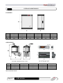
1
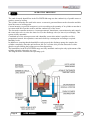
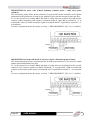
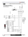
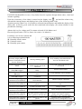
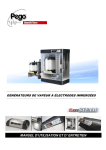
IMMERSED ELECTRODES
HUMIDIFIERS
EASYSTEAM
Use and Maintenance Manual
READ AND KEEP
REV. 02‐09
ENG
Page 2
USER MANUAL
Thank you for choosing a sunk-electrode PEGO EASYSTEAM humidifier
Read this manual carefully: doing so will ensure that installation is carried out correctly and that the
machine is used properly and efficiently.
You are therefore advised to store the manual near the humidifier so that it can be consulted for
maintenance and/or modification purposes as and when necessary.
How to read the manual.
To aid comprehension the manual contains the following symbols:
Note to be read carefully.
Indicates procedures that must be followed with due care and attention so as to prevent
damage to the humidifier, injury or malfunctions
Indicates forbidden practices and procedures which could cause damage to the humidifier,
injury or malfunctions.
Useful tip.
Indicates that the PEGO 2 HUMIDIFIER DIVISION customer service centre (phone
number given at the end of the manual) should be contacted.
USER MANUAL
Page 3
CONTENTS
INTRODUCTION
Page 6
Page 7
Page 8
Page 9
Page 10
Page 11
Page 11
Page 12
Page 13
Page 13
1.1
1.2
1.3
1.4
1.5
1.6
1.7
1.8
1.9
1.10
General
Warranty conditions
Operating principle
ES series humidifier ID codes
ES series humidifier technical data
OEM series humidifier ID codes
OEM series humidifier technical data
Overall dimensions
ID data
Standard assembly kit
INSTALLATION
Page 14
Page 16
Page 20
Page 20
Page 23
Page 26
Page 27
2.1
2.2
2.3
2.4
2.5
2.6
2.7
General informations for the installation
ES series humidifier installation
ES series humidifier electrical power connections and security
ES and OEM series control signals and sensors connections
Wiring diagrams ES and OEM series
OEM series humidifier installation
OEM series humidifier electrical connection
PROGRAMMING
Page 28
Page 29
Page 30
3.1
3.2
3.3
SLIM controller description
Level 1 programming
Level 2 programming
MASTER/SLAVE CONFIGURATION
Page 32
Page 32
4.1
4.2
Single humidifier configuration
Master/Slave humidifiers configuration
SWITCHING ON
Page 35
Page 35
5.1
5.2
Initial start-up
Steam production
TROUBLESHOOTING
Page 35
Troubleshooting guide
MAINTENANCE
Page 38
Page 38
Page 38
Page 39
Page 43
Page 4
7.1
7.2
7.3
7.4
7.5
Maintenance
General safety rules
Maintenance Intervals
Changing the cylinder
Cleaning the cylinder
USER MANUAL
CHAP. 1
CHAP. 2
CHAP. 3
CHAP. 4
CHAP. 5
CHAP. 6
CHAP. 7
STEAM DISTRIBUTION
Page 44
Page 44
Page 45
Page 45
Page 46
8.1
8.2
8.3
8.4
8.5
General
Example of in-duct steam distribution
Example of in-room steam distribution
Choosing the distribution pipe
Condensate recovery
APPENDICES
Page 47
Page 49
Page 51
9.1
9.2
9.3
EC DECLARATION OF CONFORMITY
ES series Spare parts list
OEM series Spare parts list
USER MANUAL
CHAP. 8
CHAP. 9
Page 5
CHAP.1 INTRODUCTION
GENERAL
1.1
Pego EASYSTEAM sunk-electrode humidifiers are the latest family of humidifiers to be released
onto the market: they are characterised by outstanding completeness of performance and extremely
simple maintenance.
The range includes 3 Kg/h and 6Kg/h humidifiers with single-phase power supply and 6 Kg/h, 12
Kg/h, 24 Kg/h and 48 Kg/h humidifiers with 3-phase + neutral power supply; they all feature
proportional control mode (with 4-20 mA, 0 – 10 V signal) or a simpler ON/OFF control mode.
EASYSTEAM humidifiers feature software with an extensive programming range, full
personalisation and completely automatic operation
This means that the user can set steam output to maximum or some intermediate percentage,
regulate de-concentration emptying frequency or have all the water emptied automatically when the
machine has been idle for a set time.
The EASYSTEAM line also features a display that shows real-time room humidity, the current
being absorbed by the electrodes, working hours, various warnings/alarms, water filling/emptying
status and a full range of user-friendly programming parameters.
EASYSTEAM humidifiers also incorporate a buzzer to warn the user of any faults; the internal
software evaluates the seriousness of the problems and shuts down or continues steam generation
accordingly.
A key advantage of the EASYSTEAM range is that the cylinder with the stainless steel electrodes is
easily changed when normal wear makes such replacement necessary.
Page 6
USER MANUAL
1.2
WARRANTY
EASYSTEAM humidifiers are covered by a 24-month warranty against all manufacturing defects
as from the date indicated on the product ID code or from the date of product registration card, if
present.
In the event of a defect the product must be appropriately packaged and sent to our factory or any
authorized Service Center by authority RMA number received.
Customers are entitled to have defective products repaired, spare parts and labour included.
Transport expenses and risk shall be met entirely by the customer.
Repairs carried out under warranty do not prolong or renew the warranty expiration date.
The Warranty does not cover:
• Damages resulting from tampering, impact or improper installation of humidifier and its
accessories.
• Behaviour inconsistent with Manufacturer’s prescriptions and instructions.
• Damages caused by repairs made by unauthorized persons.
• Spare parts (immersed electrodes steam cylinder)
• Damages caused by natural phenomena as lightning, natural calamities, etc.
Warranty cover may be refused if the device is modified or changed.
Under no circumstances Pego S.r.l. will be responsible for possible loss of data and information,
costs of substitutive goods or services, damages to things, people or animals, non-sale or non-gain,
activity interruption, possible direct, indirect, accidental, property, covering, punitive, special or
consequential damages anyhow caused, whether they are contractual, extra-contractual or due to
negligence or other responsibility, derived from product use or from its installation.
The wrong machine working caused by manumissions, shoves, inadequate installation
automatically forfeits the warranty right. It is compulsory to respect all information of this user
manual and device operating conditions.
PEGO S.r.l. declines any responsibility for possible errors or inaccuracies written in this manual as
a result of printing or transcription errors.
PEGO S.r.l. reserves the right to modify its products as it deems necessary without altering its
main characteristics. Each new release of a PEGO user manual replaces all the previous ones.
However not expressly indicated, the warranty follows the laws in force and particularly the section
1512 C.C. (Italian Civil Code)
For any controversy is elected by the parties and recognized the jurisdiction of the Court of Rovigo.
.
USER MANUAL
Page 7
1.3
OPERATING PRINCIPLE
The sunk-electrode humidifiers in the EASYSTEAM range use the conductivity of potable water to
produce steam by boiling.
The cylinder electrodes are sunk in the water: a current is generated between the electrodes and this
heats the water to boiling point.
Current intensity (expressed in amperes) varies according to the quantity of in-cylinder water that is
in contact with the electrode surfaces and the conductivity of the water.
The electronic controller measures, via an amperometric transformer, current intensity and controls
the water inlet valve (to raise the water level) or the discharge valve (to lower it) accordingly. This
system is fully automatic.
Combined use of the microprocessor and a humidity sensor also makes it possible to effect
proportional control: this optimizes water and electricity consumption according to required
humidity levels.
In addition to ensuring that the humidifier works properly the discharge pump also empties the
cylinder completely when the unit had been idle for a set time: this prevents limescale or other
particles created during the boiling process from depositing.
The humidifiers in the EASYSTEAM range are fully automatic and require only replacement of the
cylinder when the electrodes are worn.
The diagram below illustrates the operating cycle.
Page 8
USER MANUAL
The supplied steam is managed proportionally to steam production request that the electronic
control computes on the basis of functioning selected between the available five described at
chap. 2.4. The minimum steam
Supplied steam
supply is fixed at 20% and it is
managed by an activation
Maximum supply
hysteresis;
the
maximum
supply obtained with the
maximum steam production
request, corresponds to first
level variable set percentage
(Pr). For example if the steam
production percentage Pr, on
ES6 humidifier that produces
Minimum supply
6Kg/h of steam, is set to 100%,
the maximum supply will be
6Kg/h; but if the maximum
supply will be 3Kg/h.
Steam production request
To ensure proper humidifier performance use only mains drinking water; this is because it
is free from any harmful content and is compatible with the conductivity range needed for
optimal humidifier performance. Note that in some areas mains water may be unsuitable for optimal
performance owing to very low conductivity or very hard or too much aggressive; the following
table summarizes the parameters required for correct humidifier operation.
WATER SUPPLY OPERATING RANGE
PARAMETER
UNIT OF MEASURE
* Conductivity of water at 20° C
µS/cm
Hardness
mg/l CaCO3
Chlorine
mg/l Cl
Chlorides
ppm Cl
Calcium sulphate
mg/l CaSO4
Metalline impurities / Solvents / Soaps / Lubricants
mg/l
Temperature
°C
LIMITS
MIN MAX
250
1300
160
450
0
0,2
0
25
0
95
0
0
+1
+40
* Stated conductivity refers to water at 20° C; bear in mind that conductivity diminishes as water
temperature falls and so water may not be very conductive in winter when mains water is
particularly cold.
To avoid this inconvenience, diminish the produced steam percentage described in chapter
3 PROGRAMMING of this manual.
Do not fill the humidifier with water from wells or water that has been treated with
osmosis/demineralising/softening purifiers.
USER MANUAL
Page 9
ES SERIES HUMIDIFIER ID CODES
1.4
ES3-M
single-phase covered humidifier with steam output capacity of 3 Kg/h,
on/off work mode with external enabling, proportional mode with inbuilt
humidity switch and 4-20mA humidity sensor, proportional mode
with 0-10 V signal
ES6-M
single-phase covered humidifier with steam output capacity of 6 Kg/h,
on/off work mode with external enabling, proportional mode with inbuilt
humidity switch and 4-20mA humidity sensor, proportional mode
with 0-10 V signal.
ES6
three-phase covered humidifier with steam output capacity of 6 Kg/h,
on/off work mode with external enabling, proportional mode with inbuilt
humidity switch and 4-20mA humidity sensor, proportional mode
with 0-10 V signal.
ES12
three-phase covered humidifier with steam output capacity of 12 Kg/h,
on/off work mode with external enabling, proportional mode with inbuilt
humidity switch and 4-20mA humidity sensor, proportional mode
with 0-10 V signal.
ES24
three-phase covered humidifier with steam output capacity of 24 Kg/h,
on/off work mode with external enabling, proportional mode with inbuilt
humidity switch and 4-20mA humidity sensor, proportional mode
with 0-10 V signal.
ES48
three-phase covered humidifier with steam output capacity of 48 Kg/h,
on/off work mode with external enabling, proportional mode with inbuilt
humidity switch and 4-20mA humidity sensor, proportional mode
with 0-10 V signal.
1.5
ES SERIES HUMIDIFIERS TECHNICAL DATA
TECHNICAL DATA and
OPERATING CONDITIONS
STEAM PRODUCTION (Kg/h)
ELECTRICAL POWER SUPPLY
POWER (KW)
ABSORBED CURRENT (A)
TYPE OF CONTROL
ELECTRONIC CONTROL POWER
SUPPLY
STEAM OUTLET DIAMETER (mm)
NUMBER OF CYLINDERS
WEIGHT (EMPTY) (Kg)
WEIGHT OF WORKING UNIT (Kg)
WATER SUPPLY PRESSURE
ES3-M
3
6
230V 50-60HZ
2
3
9
13,5
ES6
ES12
ES24
6
12
24
400V 3/N 50-60HZ
4,5
9
18
6,5
13
25
SLIM EASYSTEAM
ES48
48
35
51
230V 50-60HZ
25
1
10
12
WORKING AMBIENT TEMPERATURE
WORKING AMBIENT HUMIDITY.
STORAGE TEMPERATURE
PROTECTION RATING
Page 10
ES6-M
USER MANUAL
25
1
10
13
25
1
10
13
25
1
12
18
40
1
19
37
1-10 bar
+1 ÷ +40 °C
< 60 %RH (90 %RH not condensing)
-10 ÷ +70 °C
IP20
40
2
38
74
OEM SERIES HUMIDIFIER ID CODES
1.6
ES3-M-OEM
single-phase custom humidifier complete with electronic kit with steam
output capacity of 3 Kg/h, on/off work mode with external enabling,
proportional work mode with in-built humidity switch and 4-20mA
humidity sensor, proportional operation with 0-10 V signal.
ES6-M-OEM
single-phase custom humidifier complete with electronic kit with steam
output capacity of 6 Kg/h, on/off work mode with external enabling,
proportional work mode with in-built humidity switch and 4-20mA
humidity sensor, proportional operation with 0-10 V signal.
ES6-OEM
three-phase custom humidifier complete with electronic kit with steam
output capacity of 6 Kg/h, on/off work mode with external enabling,
proportional work mode with in-built humidity switch and 4-20mA
humidity sensor, proportional operation with 0-10 V signal.
ES12-OEM
three-phase custom humidifier complete with electronic kit with steam
output capacity of 12 Kg/h, on/off work mode with external enabling,
proportional work mode with in-built humidity switch and 4-20mA
humidity sensor, proportional operation with 0-10 V signal.
ES24-OEM
three-phase custom humidifier complete with electronic kit with steam
output capacity of 24 Kg/h, on/off work mode with external enabling,
proportional work mode with in-built humidity switch and 4-20mA
humidity sensor, proportional operation with 0-10 V signal.
1.7
OEM SERIES HUMIDIFIERS TECHNICAL DATA
TECHNICAL DATA and
OPERATING CONDITIONS
STEAM PRODUCTION (Kg/h)
ELECTRICAL POWER SUPPLY
POWER (KW)
ABSORBED CURRENT (A)
TYPE OF CONTROL
ELECTRONIC CONTROL POWER
SUPPLY
STEAM OUTLET DIAMETER (mm)
NUMBER OF CYLINDERS
WEIGHT (EMPTY) (Kg)
WEIGHT OF WORKING UNIT (Kg)
WATER SUPPLY PRESSURE
WORKING AMBIENT TEMPERATURE
WORKING AMBIENT HUMIDITY
STORAGE TEMPERATURE
PROTECTION RATING
AMBIENT TEMPERATURE OF
ELECTRONIC CONTROL OPERATION
AMBIENT HUMIDITY OF ELECTRONIC
CONTROL OPERATION
ELECTRONIC CONTROL PROTECTION
RATING
ES3-M-OEM
ES6-M-OEM
3
6
230V 50-60HZ
2
3
9
13,5
ES6-OEM
ES12-OEM
6
ES24-OEM
12
400V 3/N 50-60HZ
4,5
9
6,5
13
SLIM EASYSTEAM
24
18
25
230V 50-60HZ
25
1
6
8
25
1
6
9
25
25
1
1
6
9
9
15
1-10 bar
+1 ÷ +50 °C
< 60 %RH (90 %RH non-condensing)
-10 ÷ +70 °C
IP00
40
1
11
23
+0 ÷ +60 °C
< 60 %RH (90 %RH non-condensing)
IP20
USER MANUAL
Page 11
OVERALL DIMENSIONS
1.8
ES SERIES
H
L
P
TYPE
ES3-M
ES6-M
ES6
ES12
ES24
ES48
L
P
H
430
240
525
430
240
525
430
240
525
430
240
625
430
240
710
610
290
710
OEM SERIES
H
L
P
STEAM GENERATING UNIT
ELECTRONIC KIT
TYPE
ES3-M OEM
ES6-M OEM
ES6 OEM
ES12 OEM
ES24 OEM
L
P
H
340
210
380
340
210
380
340
210
380
340
210
480
340
210
565
Measurements in mm.
Page 12
USER MANUAL
1.9
IDENTIFICATION DATA
The unit described in this manual has, on its side, an ID plate showing all the relevant identification
data:
• Name of Manufacturer
• Unit model
• Serial number
• Power supply voltage
• Rated current
1.10
STANDARD ASSEMBLY KIT
EASYSTEAM humidifiers come complete with:
N° 1 gas connector, ¾”, for water inlet.
N° 1 discharge connector, external diameter 40 mm, with fixing clip on ES models, external
diameter 25 mm on OEM models.
N° 1 steam pipe connector, external diameter 25 mm, for models from 3 to 12 Kg/h and external
diameter of 40 mm for models from 24 to 48 Kg/h with relative fixing clip.
N° 1 user’s manual.
N° 1 Final Test checklist showing:
- Humidifier model
- Default configuration
- Steam production at 100%
- Type of electrical power supply
- Absorbed power in kW
- Rated current absorption
N° 1 ELECTRONIC KIT (for OEM series models only)
- MASTER 100 (electronic control board with PEGO EASYSTEAM software)
- SLIM (electronic controller with screen for control and display)
- TOROIDAL (current absorption sensor)
- CONNECTOR (connector for cylinder connection)
USER MANUAL
Page 13
CHAP. 2 INSTALLATION
2.1
IMPORTANT INFORMATION FOR THE INSTALLER
1.
The installation, maintenance and use of the equipment must be performed by qualified
personnel capable of executing all the operations required in complete safety.
Read this manual carefully before performing any task and follow all directions
2.
Install the unit as close as possible to the point at which you wish to emit steam (i.e. a
position that minimises the length of the steam tube: this should not be more than 5 m long)
3.
Install at a height which gives easy access to the control unit used to set the parameters. An
above-ground height of about 1 metre is advised.
4.
Install at a height that allows easy access to the humidifier interior for cylinder replacement
purposes.
5.
Some humidifier’s parts, during operation, can exceed 60°C temperature. Make sure the
surfaces in contact with them are consistent with those values.
6.
Do not install and use the humidifier near to products and objects that can be damaged by
water or produced humidity.
7.
Do not fit power supply wiring and signal wiring (probes/sensors and digital inputs) in the
same raceways or ducts.
8.
Minimise the length of connector wires so that wiring does not twist into a spiral shape as this
could have negative effects on the electronics.
9.
Place a general magneto-thermal cut-off switch upstream from the electronic controller.
10.
All conductors used in wiring must be proportionate to support the load that they have to
supply.
11.
When it is necessary to make a probe/sensor extension, the wires must have a cross-section of
at least 1 mm2.
12.
Connect up the water discharge point to a hose with a diameter of at least 40 mm: make sure
the hose does not have any narrow passages and does not at any point exceed the level of the
discharge coupling.
13.
Fill with potable water only at a pressure of 1 - 10 bar.
Page 14
USER MANUAL
14.
Check that the ON/OFF, 4-20 mA, 0-10 V default setting given on the attached CHECK
LIST sheet is applied before starting the humidifier; if the default setting is different from
your needs adjust the machine software settings , with the machine on, as indicated at chapter
3 and according to the connections indicated at chap. 2.4.
15.
To function correctly humidifier needs enabling at digital input 1 with a free-voltage contact
(terminal blocks 1 and 2 on 100 Master card) indifferently from selected functioning mode.
16.
In case it’s unnecessary using of external enabling just make bridge on terminal blocks 1 and
2 on 100 Master.
17.
If enabling is missing the display will show OFF alternate to normal visualization.
USER MANUAL
Page 15
INSTALLING THE ES SERIES HUMIDIFIER
2.2
1. Remove the humidifier from the packaging: keep it vertical as you do so. Remove the nylon
cover bag and check that the unit is in good condition.
2. Fix the humidifier to the wall, preferably 1 m above the ground and perfectly level (fig. 1); use
the 4 slots at the rear to insert the fixing screws (fig. 2 and 3).
Fig. 1
Fig. 2
Page 16
Fig. 3
USER MANUAL
3. Using a screwdriver, release the safety locks at the sides of the front cover (fig. 4, 5 and 6).
Fig. 4
Fig. 5
Fig. 6
4. Extract the front cover: grip the two side handles and pull
outwards gently (fig. 7).
Fig. 7
5. Remove the protective cardboard above the cylinder
(fig. 8).
Fig. 8
USER MANUAL
Page 17
6. Connect the water drainage discharge pipe to the manifold (40 mm diameter) and fix it in place
with the supplied clip (fig. 9 e 10).
Fig. 9
Fig. 10
Only connect the discharge with pipes that are suitable for temperatures of 100 °C and
only use pipes with a diameter of at least 40 mm; do not, at any point along the line,
exceed the height of the humidifier.
NEVER USE THE HUMIDIFIER WITHOUT THE DISCHARGE LINE
CORRECTLY CONNECTED!
7. Connect the water inlet line to the ¾ GAS connector of the solenoid valve underneath the
humidifier (fig. 11 e 12).
Fig. 11
Fig. 12
Connect up the water inlet using a non-metal pipe (use e.g. rubber, PVC, polypropylene,
nylon etc.).
Page 18
USER MANUAL
8. Connect the steam pipe to the cylinder flange sleeve and fix in place with the supplied clip (fig.
13, 14 e 15).
Fig. 13
Fig. 14
Fig. 15
Use only PEGO HUMIDIFIER steam hoses or others that are certified to withstand high
temperatures without any internal vulcanisation or release of harmful substances
occurring!
THE HOSE MUST NOT BE CHOKED, HAVE ANY WATER TRAPS (SIPHONS)
OR BE LONGER THAN 5 METRES!
For instructions on correct connection of the steam distribution line read Chapter 7 STEAM
DISTRIBUTION carefully.
USER MANUAL
Page 19
ES SERIES HUMIDIFIER ELECTRICAL POWER CONNECTIONS AND
SECURITY
2.3
Connect power supply to the humidifier terminal block linking 230V to R and N terminals
for single-phase models and 400V + neutral to terminals RST and N for 3-phase models.
It is mandatory to connect the terminal marked by the yellow/green and by PE mark to
power supply earth. If necessary, verify the efficiency of the ground system.
Leave the bridge between terminals 60 and 61 or change it, if necessary, with an emergency
normally open contact.
Terminal blocks 62 and 63 are predisposed for fan unit power supply, in case you install that, please
refer to the user manual attached to the fan unit.
2.4
ES AND OEM SERIES CONTROL SIGNALS AND SENSORS CONNECTIONS
Humidifier works in five functioning modes set by software parameter S9, described at chap. 3 and
by specific electrical connections.
Moreover it is required the enabling of digital input terminal blocks 1 and 2 on 100 Master card for
all functioning modes. (in case it’s unnecessary using of external enabling just make bridge on
terminal blocks 1 and 2 on 100 Master). If enabling is missing the display will show OFF alternate
to normal visualization.
Below description of specific connections for each functioning mode.
In case it’s needed to connect 4-20mA probes not supplied by PEGO S.r.l. please call
the technical dept. to verify hardware compatibility of the probe with humidifier.
-
ON/OFF MODE:
This kind of functioning allows steam production in only 2 modes: total lack of production or
production at maximum. Enabling is generally provided by a free-voltage contact coming from
an electrical panel controlled by a humidity sensor. To set the second level variable S9=0 and
connect the enabling (normally open free-voltage contact) to terminal blocks 1 and 2 on 100
Master.
Segnale
ON‐OFF
Enabling
Steam production request
Page 20
USER MANUAL
-
PROPORTIONAL mode with 0-10Vdc reference signal:
This kind of functioning allows steam production proportionally to reference signal 0-10V.
Example: a 6V reference signal will lead humidifier to produce 60% of steam referring to
software variable Pr. So if Pr= 70% will be 42%. To set the second level variable S9=2 and
make a bridge between terminal block 11 and 12, connect 0-10V reference signal to terminals
13 and 14, +V to terminal 13, GND to terminal 14.
Segnale esterno di
riferimento 0‐10V
Enabling
External 0‐10 V
reference signal
Steam production request
-
PROPORTIONAL mode with 4-20mA humidity probe:
This kind of functioning allows steam production in proportional mode, humidifier will regulate
automatically the production of steam as per ambient request. Enabling is provided by a 420mA humidity probe that regulates steam production, also allowing visualization of ambient
relative humidity, directly on humidifier display. To set the second level variable S9=1 and
make a bridge between terminal block 10 and 11, connect 4-20mA humidity probe signal to
terminals 8 and 9, signal RH to terminal 9, +V to terminal 8.
RH% Amb. humidity
transducer
-
Enabling
RH% Amb. humidity
transducer (4‐20mA)
Steam production request
The proportional band Bp is the percentage value of humidity near to the set point, inside this
value the humidifier works in proportional mode. Example: if the proportional band is set on
default value 10% (-5% / +5% set point value) and the humidity is set to 50%, under 45% the
humidifier will works to 100% of steam production; over 55% of humidity the humidifier will
not produce steam. Between 45% and 55% the humidifier will adjust the steam production
optimally.
USER MANUAL
Page 21
-
PROPORTIONAL mode with 4-20mA humidity ambient probe + limit duct probe
(4-20mA):
This functioning mode allows steam production in proportional mode, humidifier will regulate
automatically the production of steam as per ambient request and the measured value into duct.
To set the second level variable S9=3 and make a bridge between terminal block 10 and 11,
connect 4-20mA humidity probe signal to terminals 8 and 9, signal RH to terminal 9, +V to
terminal 8. Connect 4-20mA duct probe signal to terminals 6 and 7, signal RH to terminal 7, +V
to terminal 6.
For more explanations about duct probe see chap. 3 “PROGRAMMING” (StC, r0, t1 variables).
Enabling
RH% Duct humidity
probe (4‐20mA)
-
RH% Amb. humidity
transducer (4‐20mA)
PROPORTIONAL mode with 0-10Vdc reference signal + limit duct probe 4-20mA:
This functioning mode allows steam production in mode proportional to 0-10V reference signal
and the measured humidity into duct.
To set the second level variable S9=4 and make a bridge between terminal block 11 and 12,
connect 0-10V reference signal to terminals 13 and 14, +V to terminal 13, GND to terminal 14.
Connect 4-20mA duct probe signal to terminals 6 and 7, signal RH to terminal 7, +V to terminal
6.
For more explanations about duct probe see chap. 3 “PROGRAMMING” (StC, r0, t1 variables).
Enabling
RH% Duct humidity
probe (4‐20mA)
Page 22
USER MANUAL
External 0‐10 V
reference signal
Power supply
230Vac Single‐phase
50/60Hz
Power
terminal block
Connector
KM1
Level
Enabling and probes
terminal block
LEGENDA:
KM1: Contactor
TA1: Current transformer
P1: Drain pump
EV1: Solenoide valve
Humidifier
electrodes
Page 23
USER MANUAL
Emergency
close contact
Fan unit
Wiring diagrams models:
ES3-M-OEM / ES6-M-OEM
ES3-M / ES6-M
-
WIRING DIAGRAMS ES AND OEM SERIES
2.5
Power supply
50/60Hz
400Vac three‐phase + N
Fan unit
Power
terminal block
Connector
Humidifier
electrodes
Level
LEGENDA:
KM1: Contactor
TA1: Current transformer
P1: Drain pump
EV1: Solenoid valve
Enabling and probes
terminal block
USER MANUAL
Page 24
Emergency
close contact
Wiring diagrams models:
ES6-OEM / ES12-OEM / ES24-OEM
ES6 / ES12 / ES24
-
Power supply
50/60Hz
Power
terminal block
Humidifier
electrodes
Lev. 1
Connector 2
Enabling and probes
terminal block
LEGENDA:
KM1: Contactor
KM2: Contactor 2
TA1: Current transformer 1
TA2: Current transformer 2
P1: Drain pump
EV1: Solenoid valve
Lev. 2
Humidifier
electrodes 2
Page 25
USER MANUAL
Emergency
close contact
Fan unit
Connector 1
400Vac three‐phase + N
- Wiring diagram model:
ES48
INSTALLING THE OEM SERIES HUMIDIFIER
2.6
1. Remove the humidifier from the packaging: keep it vertical as
you do so. Remove the nylon cover bag and check that the unit is
in good condition.
2. Fix the humidifier so it is level above the cell or base by inserting
the fixing screws in the 4 holes of the support base (fig. 17).
Fig. 17
3. Connect the water discharge (emptying) pipe to the manifold (25
mm diameter) and fix it in place with the supplied clip (fig. 18 and 19).
Fig. 18
Fig. 19
The discharge hose must not be choked/pinched
or create pressure: if it does the installation of a
vent on the discharge line (as shown in fig. 20)
is essential.
Fig. 20
Only connect the discharge with pipes
suitable for temperatures of 100 °C and only
use pipes with a diameter of at least 25 mm;
do not, at any point along the line, exceed the height of the humidifier.
NEVER USE THE HUMIDIFIER WITHOUT THE DISCHARGE LINE
CORRECTLY CONNECTED!
Page 26
USER MANUAL
4. Connect the water inlet line to the ¾ GAS connector of the solenoid valve (fig. 21 and 22).
Fig. 21
Fig. 22
Connect up the water inlet using a non-metal pipe (e.g. rubber, PVC, polypropylene, nylon
etc.)
5. Connect the steam pipe to the cylinder flange sleeve and fix it in place with the supplied clip (fig.
23 and 24.
Fig. 23
Fig. 24
THE HOSE MUST NOT BE CHOKED, HAVE ANY SIPHONS OR BE LONGER
THAN 5 METRES
For instructions on correct connection of the steam distribution line, read Chapter 8 STEAM
DISTRIBUTION carefully.
2.7
OEM SERIES ELECTRICAL HUMIDIFIER CONNECTION
Humidifiers belonging to the OEM series are characterised by a steam generating unit and
a separate electronic kit. Electrical connections are the responsibility of the customer and
they are the same described at paragraphs 2.3, 2.4, 2.5.
If you wish to make settings different from the default ones, carry out the procedures given at
paragraph 2.4.
USER MANUAL
Page 27
CHAP. 3 PROGRAMMING
DESCRIPTION OF SLIM CONTROLLER
3.1
1. The SLIM CONTROLLER is the control unit on the front of the humidifier. It consists of an 8LED display to visually check values (fig. 25) and 6 keys to adjust display and modify settings (fig.
26).
Relative humidity %
visualization
Steam being produced
Current absorbed (A)
visualization
Steam output %
visualization
Water inlet
Display
On = Water drain
Blinking = Water drain test
Alarm
Fig. 25
Used to display absorbed current or
steam production (%)
UP key, alarm mute
ON/OFF
Stand-by key
SET key, room humidity
display and programmed
humidity set point. (not
used on the ON/OFF and
0-10V version)
DOWN key
Fig. 26
Page 28
USER MANUAL
Manual water
emptying
LEVEL 1 PROGRAMMING
3.2
1. Level 1 programming allows the user to modify 2 important parameters, the proportional band
Bp and the steam production percentage Pr.
VAR.
MEANING
VALUES
DEFAULT
all models
Pr
Steam production percentage
20 ÷ 100 %
100 %
Bp
Proportional band
(not used on the ON/OFF versions)
1 ÷ 20 Rh%
10 %
25 ÷ 99 Rh%
99%
1 ÷ (StC – 20) Rh%
0-100%
50%
only read
StC
r0
UrC
Max humidity set point in duct Outgoing set point value humidifier will
switch off and start functioning again when humidity into duct will go below
the value StC – r0 adding t1 time, following the logic sent by 0-10V signal or
by ambient humidity sensor
Max humidity set point in duct differential
Humidity duct sensor value
The proportional band Bp is a percentage humidity value around the set point; within this
band the humidifier works in proportional mode.
Example: if proportional mode is set to the default value of 10% (-5% / +5% with reference to the
set point) and humidity is set to 50%, then below 45% the humidifier works at 100% steam output;
above 55% the humidifier does not produce any steam at all. Between 45 and 55% the humidifier
will optimise steam output.
The steam percentage value Pr is the value the humidifier is able to reach at maximum output. For
example, leaving the setting at 100% on an ES6 rated at 6 Kg/h will give 6 Kg/h of steam output; if
the Pr setting is reduced to 50% the humidifier will produce 3 Kg/h at most.
The Pr variable is highly useful where water conductivity is poor and when you need to
make the most of the cylinder when it is nearing replacement; for further information
consult chapter 6 TROUBLESHOOTING of this manual at page 25.
The humidity duct set point (stC) is an humidity limit into duct. If the humidity in duct is higher the
humidifier stop steam production and restart when the duct humidity is less than StC-r0. Consider
an additional time delay (t1 on second programming level) before the steam production start again.
To gain access to the Level 1 programming menu proceed as follows:
- Press the (t) and (u) keys simultaneously and keep them pressed for a few seconds until the
first programming variable appears on the display.
- Release the (t) and (u) keys.
- Select the variable to be modified using the (t) or (u) key.
- When the variable has been selected it is possible:
- to display the setting by pressing SET
- to modify the setting by pressing the SET key and the(t) or (u) keys.
- When configuration values have been set you can exit the menu by pressing the (t) and (u)
keys simultaneously for a few seconds until the parameter shown before programming was
accessed (e.g. steam production or absorbed current) reappears.
The new settings are saved automatically when you exit the configuration menu.
USER MANUAL
Page 29
3.3
LEVEL 2 PROGRAMMING
1. Level 2 programming allows the user to modify a number of advanced humidifier settings.
These parameters should not be modified without guidance from a PEGO assistance centre or a
specialised technician
DEFAULT
VAR.
MEANING
VALUES
ES3-M
ES6-M
ES-12
S0
S1
Duration time for de-concentration pump drain
Working hours
De-concentration discharge interval
Interval, in working (steam production) minutes, for deconcentration discharge
Delay time on electrodes current-flowing start after a
pump drain
0.1 ÷ 12.7 s
Ten hours
2
-
2
-
3
-
5
-
1 ÷ 250 min
15
15
15
15
1 ÷ 12 s
2
2
2
2
1
1
1
1
1
0,7
1
1
25
0.5
25
0.5
20
0.5
15
0.5
0.1
0.1
0.3
0.5
0
0
0
0
0%
0%
0%
0%
0%
0%
0%
0%
10 s
10 s
10 s
10 s
0
0
0
0
0
0
0
0
5
5
5
5
S2
S3
This parameter, if increased, allows in some particular
installation conditions to avoid problem of differential
intervention delay on power supply line affecting speed of
restarting after water draining
Water discharge following period of non-use
1 – 24 h
Cylinder emptied completely because machine has been
idle for the set period
Minimum current differential between one water fill
0.2 ÷ 10 A
S5 and the next
1 ÷ 50 %
S6 Pump activation overcurrent percentage
0.1 ÷ 5.0 s
S7 Pump discharge time overcurrent
Minimum current differential for water feed during
0.0 ÷5.0 A
S8 total or partial cylinder filling
S8=0.0 set the cylinder filling step-by-step
Settings:
S9=0 ON-OFF
S9=1 PROPORTIONAL WITH SENSOR 4-20mA
S9=2 PROPORTIONAL WITH INPUT 0-10V
S9 S9=3 PROPORTIONAL WITH SENSOR 4-20mA and 0-1-2-3-4
max limit in duct (4-20mA)
S9=4 PROPORTIONAL WITH INPUT 0-10V and
max limit in duct (4-20mA)
Humidity sensor calibration
-20 % ÷ 20 %
CA1 (not used on ON/OFF versions)
-20 % ÷ 20 %
CA2 Humidity duct sensor calibration
Time delay humidity duct (in seconds).
This time delay start when there are the condition to
0-240 s
t1
produce steam in the duct ( duct humidity < StC-r0)
(used only with S9=3 and S9=4)
S4
Ad
MS
rEL
Lan address for connection to TeleNET supervision system
0 ÷ 31
or master-slave configuration
Master-Slave functioning setting
0= Single
4= Master + 3 slave
0-1-2-3-4-5-6
1= Slave
5= Master + 4 slave
2= Master + 1 slave
6= Master + 5 slave
3= Master + 2 slave
only read
Release software
Page 30
USER MANUAL
ES-6
ES-24
ES-48
2. To access the second programming level press the UP (t) and DOWN (u) keys and the
WATER DISCHARGE key simultaneously for a few seconds. When the first programming
variable appears the system automatically goes to stand-by.
- Select the variable to be modified by pressing the UP (t) or DOWN (u) keys.
- When the parameter has been selected it is possible to:
- View the setting by pressing the SET key.
- Modify the setting by holding the SET key down and pressing the (t) or (u) key.
- When configuration settings have been completed you can exit the menu by pressing the (t) and
(u) keys simultaneously and keeping them pressed until the room humidity value (0.0 on ON/OFF
versions) reappears.
Changes are saved automatically when you exit the configuration menu.
Press the ON/OFF - STAND-BY key to enable electronic control (when you enter Level 2
programming the humidifier automatically goes to STAND-BY mode).
USER MANUAL
Page 31
CHAP. 4 MASTER SLAVE CONFIGURATION
4.1
SINGLE HUMIDIFIER CONFIGURATION (default configuration)
The humidifier is set as "single" (MS=0) and works in autonomous way following the setting
given in S9 variable.
Humidity
sensor
MS=0
Ad=0
SINGLE
4.2
MASTER + SLAVE HUMIDIFIERS CONFIGURATION
In this configuration the humidifiers (up to 6 units) work as if they were a one unit producing
steam according to a common reference given from Master unit.
Moreover the Master manages the pecedences of de-concentration discharge or of various
humidifiers test (included its own) with FIFO (First In First Out) modality (one single deconcentration discharge at a time) thus ensuring continuity in steam production.
Connection between Master and slave:
The humidifier set as master communicates with various slave humidifiers through a serial
connection RS-485 between various 100-Master electronic controls.
Maximum connection length is not definite but it depends by cable quality and by relation
signal/noise. The length is fixed at about 500 meters.
The connection cable can be shieldless if distance is few meters in an electrically little “noisy”
ambient. For distances included between 15 and 100 meters it is possible to use a shielded and
twisted cable without particular features, whereas for connections over 100 meters it is
suggested to use, for example, BELDEN 8762 cable.
Communication line should be chain-type avoiding star connection.
The shield of used cable should be put to earth to one side. To avoid of lodging the serial
connection RS-485 in the same ducts (or hoses) of supply or power cables.
Page 32
SLAVE-2
SLAVE-1
MASTER
100-MASTER
100-MASTER
100-MASTER
RS-485
A
B
RS-485
A
B
RS-485
A
B
17
17
17
18
USER MANUAL
18
18
Master/slave addressing:
Parameters MS and Ad setting of various units in this configuration is fixed and follows this
rule:
Parameters configuration in Master unit:
Ad =
0
Address of control Master
MS=
2
With control Master + slave1
3
With control Master + slave1+ slave2
4
With control Master + slave1+ slave2+ slave3
5
With control Master + slave1+ slave2+ slave3+ slave4
6
With control Master + slave1+ slave2+ slave3+ slave4+ slave5
Parameters configuration in slave1 unit:
Ad =
1
(Ad Master +1)
MS=
1
slave
Parameters configuration in slave2 unit:
Ad =
2
(Ad Master +2)
MS=
1
slave
Parameters configuration in slave3 unit:
Ad =
3
(Ad Master +3)
MS=
1
slave
Parameters configuration in slave4 unit:
Ad =
4
(Ad Master +4)
MS=
1
slave
Parameters configuration in slave5 unit:
Ad =
5
(Ad Master +5)
MS=
1
slave
Humidity
sensor
MS=1
Ad=5
MS=1
Ad=4
MS=1
Ad=3
SLAVE-5
SLAVE-4
SLAVE-3
MS=1
Ad=2
SLAVE-2
MS=1
Ad=1
SLAVE-1
MS=6
Ad=0
MASTER
RS‐485
USER MANUAL
Page 33
Functioning description:
The unit set as Master talks constantly with connected slaves through RS485 sending them the
information about quantity steam to produce (0-100%) and managing various units priorities
related to de-concentration discharges or test.
Functioning mode of Master/Slave whole of units is set only on Master through variable S9 as
the eventual connection of ambient humidity sensor, of duct humidity sensor, of 0-10V
reference signal, the ON-OFF enabling and desired humidity value setting.
Pr variable, that represents the steam production percentage to maximum running, is instead set
on every single unit.
The enabling lack (terminal blocks 1 and 2 open on 100Master card) generates the following
actions:
- On Master unit stops the same Master unit and all connected slave units (displaying OFF
blinking).
- On Slave units stops only the concerned slave unit (displaying OFF blinking).
Stand-by inserting through dedicated key, generates the following actions:
- If actuated on Master unit, it puts the humidifier in stand-by (stand-by led blinking) and
brings to 0 the steam production request of connected slaves.
- On Slave units stops only the concerned slave unit putting in stand-by the humidifier (standby led blinking).
If the Master does not find a slave, after a 15 sec. timeout time, signals the problem with a
silencing alarm message (E7). This alarm does not stop the normal functioning. The slave
polling continues and, if the communication starts again, the error is reset automatically.
If the Slave has not polled by the Master within a 15 sec. timeout time, it considers the
connection interrupted and it leads the steam production to 0 disconnecting the electrodes and
signaling the fault with silencing alarm (E8). In the case the connection starts again, the error is
reset automatically and the system starts its normal working.
On set Slave (mS=1) humidifiers S9 variable is not considered, steam production follows in
proportional mode the information sent to RS485 by Master.
De- concentration discharge and test priorities management:
De-concentration discharge and diagnostic tests priorities are managed as follow:
Slave units, when polled, send the eventual discharge request to the Master that manages them
FIFO (first input / first output).
The Master waits for 3 minutes before giving the next enable to pending unit following the
FIFO priority; this procedure permits to currently discharging unit to start again the steam
production.
The Slave unit that has requested a discharge wait for Master enable for 45 minutes and when
they are passed the discharge will still be executed (Time out).
Page 34
USER MANUAL
CHAP. 5 SWITCHING ON THE HUMIDIFIER
INITIAL START-UP
5.1
1. Check that default setting is compatible with signal connection; if it is different, set the
jumpers correctly before powering up as described on chapter 2.3 and 2.4.
2. Before powering up the humidifier check for correct connection of phases and signal type
(humidity sensor, N.O. contact or 0 - 10V); check for correct connection of the water mains,
excess water discharge and steam pipes.
If the mains water feed line consists of piping that might contain oily residues or other foamgenerating substances it is essential that it be washed out by letting water flow through for
several minutes.
3. To verify the absence of water loss internally the humidifier
4. Power up the humidifier.
5. The humidifier will carry out a water discharge for several seconds as it emits a prolonged beep.
6. At this point the humidifier is in STAND-BY mode; to switch it on press the ON/OFF –
STAND-BY key. On models configured in 4-20 mA PROPORTIONAL mode the humidifier
will display the humidity level detected by the sensor. For models configured in ON/OFF and
PROPORTIONAL 0-10V mode current absorption is displayed.
7. To function correctly humidifier needs enabling at digital input 1 with a free-voltage contact
(terminal blocks 1 and 2 on 100 Master card) indifferently from selected functioning mode.
If enabling is missing, the display will show OFF alternate to normal visualization
5.2
STEAM PRODUCTION
1. Set the required humidity by pressing the SET key. On PROPORTIONAL 4-20 mA
models increase the value with the UP key (if the setting is higher than that detected by
the sensor steam will be produced); on ON/OFF or PROPORTIONAL 0-10 V models give
ON/OFF enable.
2. Let the cylinder fill until the water starts to boil; empty the cylinder completely using the
MANUAL DISCHARGE key to prime the pump and repeat the procedure once or twice.
3. At this point the humidifier is operative and will work autonomously.
USER MANUAL
Page 35
CHAP. 6 TROUBLESHOOTING
EASYSTEAM humidifier in case of any faults alerts the operator through alarm codes, visual and
acoustic signaling.
Upon the occurrence of an alarm is turned on the display icon
, activated the alarm relay,
activated the internal buzzer and displayed one of the following alarm codes.
Anytime pressing "Mute" key it is possible to silent the internal buzzer and inhibit the display of the
alarm code. A next key press resets the alert sound and codes display (for serious alarms it is not
possible the silencing).
Alarm relay is a free-voltage and CO contact on board of 100-Master card
Electrical specification: 250 Vac; Imax: 8A resistive 1A inductive.
It switches over in case of alarm and
it is on following terminal blocks:
22: Normally closed contact
23: Common contact
24: Normally open contact
FAULTS
Humidifier is on but
alternately display OFF and
normal visualization and it
doesn’t fill water
Humidifier blocked with En
alarm
The humidifier is on but
alarm E0 is tripped
Block of the humidifier with
E0 alarm
The humidifier is on but
alarm E0 is tripped
Water level high, triggering
maximum level alarm E1
Water level high, triggering
maximum level alarm E1
Water level high, triggering
maximum level alarm E1
Water level high, triggering
maximum level alarm E1
CAUSE
TASKS TO BE CARRIED OUT
Missing enabling signal
Verify enabling on terminal blocks 1
and 2 on 100 Master card
Lack of connection between
SLIM controller and TLD
electronic
Sensor connection inverted or
faulty
Functional fault of humidity
sensor
Software setting of S9 variable
is incorrect
Incorrect connection of cylinder
feed connector
Water conductivity below 200
µS/cm
Diminish steam output % production
Pr
Cylinder electrodes worn
Change cylinder
One of the phases is interrupted
Check absorption on all phases
Foam production, triggering
maximum level alarm E1
Suspended particles produced by
oils or greases in the inlet line
Foam production, triggering
maximum level alarm E1
Water conductivity above 1300
µS/cm
Page 36
USER MANUAL
Verify right connection between the
two boards
Restore sensor enable
Verify humidity sensor condition
Check variable S9 setting
Check for proper connection
Carry out several complete cylinder
flushes with manual emptying
immediately after complete filling
Diminish the de-concentration
discharge time by setting S2 to a lower
FAULTS
CAUSE
Water level high, triggering
level alarm E1 with high
absorption
Damaged electronics
Block of the humidifier with
E2 alarm
The humidifier produces not
much steam
Block of the humidifier with
E3 alarm
Block of the humidifier with
E3 alarm
Block of the humidifier with
E3 alarm
Humidifier is on and
functioning but display E5
error
Unit block with E6 alarm
(not stoppable sonorous
signalation)
interval
TASKS TO BE CARRIED OUT
Contact the assistance centre
Functional fault of humidity
duct sensor
Verify humidity duct sensor condition
One of phases is interrupted
Check absorption on all phases
Lack of water more than 30
minutes of continuous request
Lack of water more than 30
minutes of continuous request
Lack of water more than 30
minutes of continuous request
Check that water supply system is
working
Make sure there is no leaking from
damaged pipes
Check the solenoid valve was not
damaged or disconnected
Verify that drain of bottom of cylinder
is not obstructed and pump is not
broken or disconnected.
Alarm is automatically resetted at next
drain control autotest which happens
every 10 hours of electrode functioning
or when humidifier is switched off.
Drain control autotest failed
(pre-alarm). Solve the problem
before next test which is
executed every 10 hours of
electrode functioning.
Drain control autotest failed for
second time. Humidifier enters
in stand-by mode to avoid
damaging of the unit.
Switch off the humidifier, solve
the problem and then switch on
again.
In a Master/slave
humidifiers configuration
the MASTER unit is on and
working but signals E7
alarm
In a Master/slave humidifiers
configuration the Master unit do
not find a connected slave.
This alarm does not stop the
normal working.
In a Master/slave
humidifiers configuration
the slave unit is blocked and
signals E8 alarm
In a Master/slave humidifiers
configuration slave unit has lost
the communication with
connected Master.
This alarm blocks the slave unit.
Humidifier differential
protection upstream the line
intervenes
Water presence on lower part of
humidifier because of a fault or
after a maintenance that cause an
earth leakage of the unit.
USER MANUAL
Verify that drain of bottom of cylinder
is not obstructed and pump is not
broken or disconnected.
Alarm is resetted when humidifier is
switched off.
Check connections between master unit
and slave unit.
Check second level parameters MS e
Ad related to Master/slave
configuration.
In case of connection restore the alarm
is automatically reset.
Check connections between master unit
and slave unit.
Check second level parameters MS e
Ad related to Master/slave
configuration.
In case of connection restore the alarm
is automatically reset.
Lead the unit to safety following the
instructions at chap. 7.2.
To wipe carefully all wet parts and
reactivate the unit.
Page 37
CHAP. 7 MAINTENANCE
MAINTENANCE
7.1
To ensure working safety, correct functioning and an optimal output of EASYSTEAM humidifiers,
it is necessary to execute maintenance operations according to following instructions.
GENERAL SAFETY RULES
7.2
Every type of maintenance has to be done exclusively by experienced and qualified
technical staff, conscious about necessary safety.
Before starting any maintenance procedure, to proceed as follows:
1. If unit is out of service because of an alarm condition, to note the displayed error code.
2. To close the valve of water supply.
3. To put the humidifier in stand-by using the proper key and discharge completely the water
contained in the cylinder using the key “Manual water emptying” on Slim Controller (see chap.
3).
4. To disconnect the unit from the electric system sectioning the power input permanently
padlocking it on OFF.
5. To wait the cylinder and the humidifier have cooled or to use protection gloves.
6. Each unit element, if it is defective, has to be replaced exclusively with original spare parts.
MAINTENANCE INTERVALS
7.3
Following are indicated the maintenance operations to execute and their suggested frequency.
Being electrodes consumption and incrustations and solid deposits formation into the cylinder
variables according to the type of water (also with the same conductivity), it could be necessary to
modify these intervals.
To verify this need checking the deposits quantity into the cylinder; a quickly accumulation of
incrustations and deposits requires to increase the suggested maintenance frequency and/or the deconcentration discharges parameters variation.
To minimize residual formation on the bottom of cylinder it’s advisable to increase
deconcentration drain frequency reducing value of S2 parameter. This trick has
disadvantage of bigger water and energy consumption.
Page 38
USER MANUAL
MAINTENANCE INTERVENTION
FREQUENCY
To verify there are not water losses internally the humidifier.
after 1 hour of working
To verify electrical connections clamping.
after 4 weeks of working
To verify there are not water losses internally the humidifier.
To verify the cylinder state, to remove incrustations and deposits if
monthly or every
present.
500 hours of working
To replace the cylinder if necessary.
To verify cylinder electrodes consumption and the absence of
quarterly or every
deformations or darkening on their surface; to replace the cylinder if
1000 hours of working
worn and torn and if it shows manifets faults.
To replace the cylinder.
yearly or every
To verify electrical connections clamping and water and steam
2500 hours of working
connections good state.
To verify there are not water losses internally the humidifier.
To verify cylinder state, to verify electrodes consumption, to remove
with alarm code E1
incrustations and deposits if present and to replace the cylinder if
necessary.
To verify there are not water losses internally the humidifier.
To verify that the solenoid valve is not disconnected or broken and to
with alarm code E3
replace it if necessary.
To verify that the drain pump is not disconnected or broken and to
replace it if necessary.
with alarm code E5 or E6
If present to remove incidental obstructions on cylinder bottom and/or
in draining pipes.
USER MANUAL
Page 39
CHANGING THE CYLINDER
7.4
The only part of the humidifier subject to wear is the electrode cylinder. This wears
according to how much the machine is used or it is not possible to remove the internal
incrustations.
The EASYSTEAM range features stainless steel electrodes to maximise durability: however,
durability will largely depend on the quality of the water (conductivity and hardness) and on how
much the machine is used.
When the electrodes are worn the water level will rise excessively and trip the maximum level
alarm E1 several times: the cylinder must, at this point, be replaced.
Once you have checked that this alarm does not have other causes (see Chap. 6 – Troubleshooting)
change the cylinder. Proceed as follows:
NEVER CHANGE THE CYLINDER WITH THE MACHINE HOT AND WITH
WATER INSIDE IT. EMPTY ALL THE WATER FROM THE CYLINDER USING
THE MANUAL DISCHARGE KEY FIRST! IT IS COMPULSORY TO FOLLOW
THE INSTRUCTIONS REPORTED AT CHAPTER 7.2.
1. Open the humidifier by removing the front cover as indicated on page 14 (on OEM models this
is not necessary).
2.
Unhook the frontal retainer spring from the upper steam flange and slide it off (Fig. 27, 28, and
29).
Fig. 27
Page 40
Fig. 28
USER MANUAL
Fig. 29
3. Unhook the rear retainer spring from the upper steam flange and
slide it off (Fig. 30).
Fig. 30
4. Raise the upper steam flange, detaching it from the cylinder
(fig. 31).
Fig. 31
5. Detach the electrical connector from the cylinder (fig. 32)
Fig. 32
6. Remove the cylinder from the lower flange by raising it (fig. 33) and then remove it from the
humidifier (fig. 34).
Fig. 33
Fig. 34
USER MANUAL
Page 41
7. Insert the new cylinder by repeating the above procedure in reverse order; check that the new
cartridge has the 2 supplied O-rings and that they are positioned correctly.
If necessary to use on O-rings and flanges the lubricating issued with the humidifier for making
their insertion easier (fig. 35 and 36).
Fig. 35
Fig. 36
8. Flush the cylinder completely 2 – 3 times immediately after replacement: do this by pressing the
“manual empty” key
9. To verify there are not water losses internally the humidifier after 1 hour of working from
cylinder replacing.
If there is a power supply failure during
cylinder replacement empty the cylinder by
detaching the filling hose from the relevant
solenoid valve (fig. 37).
Fig. 37
Page 42
USER MANUAL
7.5
CLEANING THR CYLINDER
When presence of incrustations and deposits into the cylinder prevents an adequate
passage of current between electrodes or thwarts the water discharge, it is necessary a
cleaning operation of cylinder.
NEVER CHANGE THE CYLINDER WITH THE MACHINE HOT AND WITH
WATER INSIDE IT. EMPTY ALL THE WATER FROM THE CYLINDER USING
THE MANUAL DISCHARGE KEY FIRST! IT IS COMPULSORY TO FOLLOW
THE INSTRUCTIONS REPORTED AT CHAPTER 7.2
1. Remove the cylinder from humidifier following steps from 1 to 6 described at chapter 7.4
2. Utilizing the hole on upper side of cylinder, to clean and remove the incrustations on the
electrodes and on accessible parts with a mechanical action using a plastic spatula and running
water or with a solution of water and 20% acetic acid (fig. 38). Execute the same operation on
slits of lower filter (fig. 39). During clearing operations do not damage or scrape coupling parts
that assure hydraulic seal as O-ring housing or flanges’ entrance. During clearing operations do
not wet the connector or cables holder ring UM-CA-01 (fig. 40).
Fig. 38
Fig. 39
Fig. 40
3. Clean and control the two O-ring integrity, replace them if necessary and verify their correct
positioning in the two predisposed housings on cylinder. Insert the cylinder by repeating the
above procedure in reverse order and verify its correct positioning. In coupling use the
lubricating issued with the humidifier for making readjustment operations easier.
4. Flush the cylinder completely 2 – 3 times immediately after replacement: do this by pressing the
“manual empty” key.
5. To verify there are not water losses internally the humidifier after 1 hour of working from
cylinder replacing.
USER MANUAL
Page 43
CHAP. 8 STEAM DISTRIBUTION
GENERAL
8.1
Attainment of good steam distribution and therefore the desired humidity level in any
environment depends on two key factors: the quantity of steam introduced into that
environment and how it is distributed.
If, in fact, the steam is introduced into an environment in a heterogeneous manner there will be
zones of excessive humidity and zones that are too dry: this can lead to excessive condensation and
problems in controlling steam production due to the triggering of a “pendulum” feedback effect.
It is advisable to introduce steam by inserting a PEGO distribution lance in the air duct or in front of
a ventilation unit (where the steam is introduced directly into a room and not through a duct).
8.2
EXAMPLE OF IN-DUCT STEAM DISTRIBUTION
The PEGO distribution lance must be
inserted perpendicularly to the direction of
air flow in the duct.
To optimise distribution efficiency the lance
must cover as much of the effective air flow
width as possible
(fig. 41).
Fig. 41
Page 44
USER MANUAL
EXAMPLE OF IN-ROOM STEAM DISTRIBUTION
8.3
The PEGO distribution lance must be inserted
perpendicularly in front of the air outlet vents of
a ventilation unit.
To optimise distribution efficiency the lance
must cover as much of the effective air flow
width as possible (fig. 42).
Fig. 42
CHOOSING THE DISTRIBUTION PIPE
8.4
CODE
TOTAL LENGTH
STEAM DISTRIBUTOR LENGTH
DIAMETER
UMILAN25X200
UMILAN25X250
UMILAN25X350
UMILAN25X500
UMILAN25X650
UMILAN25X800
UMILAN25X1000
UMILAN25X1050
UMILAN25X1100
UMILAN40X200
UMILAN40X250
UMILAN40X350
UMILAN40X500
UMILAN40X650
UMILAN4025X800
UMILAN40X1000
300 mm
350 mm
450 mm
600 mm
750 mm
900 mm
1100 mm
1150 mm
1200 mm
300 mm
350 mm
450 mm
600 mm
750 mm
900 mm
1100 mm
200 mm
250 mm
350 mm
500 mm
650 mm
800 mm
1000 mm
1050 mm
1100 mm
200 mm
250 mm
350 mm
500 mm
650 mm
800 mm
1000 mm
25
25
25
25
25
25
25
25
25
40
40
40
40
40
40
40
The PEGO 2 HUMIDIFIER DIVISION can supply custom-sized distribution lances. To
request a lance different from those given in the table above indicate.
USER MANUAL
Page 45
8.5
CONDENSATE RECOVERY
1. Independently of the type of application, a certain
amount of condensation will be generated inside the
distribution lance.
This condensation must be discharged so as not to
obstruct the flow of steam. If the lance is positioned
at a point higher than the humidifier and the steam
pipe has no water traps (siphon-like bends) then the
condensate recovery device need not be installed
(e.g. fig. 43).
Fig. 43
2. If the lance is positioned at a point higher than the humidifier and the steam pipe does have
siphon-like bends (e.g. fig. 44) it will be necessary to install a condensate recovery device. This
is a special hose that connects to the relevant cylinder manifold and carries the condensate
directly into the humidifier cylinder (fig. 45). The condensate can also be carried to a drain.
Recovery is effected by connecting the special hose (PEGO UMITUBODN10) to the 10 mm
diameter lance manifold. When routing the recovery hose from lance to humidifier or from
lance to drain it is necessary to create a water trap: do this by making a complete turn with a
minimum diameter of 200 mm; the siphon must also be filled with water prior to installation.
This will stop steam from exiting the condensate recovery hose (fig. 44).
Fig. 44
Fig. 45
3. If the lance is positioned below the humidifier as is generally the case on OEM humidifier
installations the condensate must be recovered by directing it into a drain.
Page 46
USER MANUAL
CHAP. 9 APPENDICES
EC DECLARATION OF CONFORMITY
9.1
COSTRUTTORE / MANUFACTURER
PEGO S.r.l. Via Piacentina, 6/b 45030 Occhiobello (RO) – Italy –
Tel. (+39) 0425 762906 Fax. (+39) 0425 762905
DENOMINAZIONE DEL PRODOTTO / NAME OF THE PRODUCT
MOD.:
MOD.:
ES3-M ; ES6-M ; ES6 ; ES12 ; ES24 ; ES48
ES3-M-OEM ; ES6-M-OEM ; ES6-OEM ; ES12-OEM ; ES24-OEM
IL PRODOTTO E’ CONFORME ALLE SEGUENTI DIRETTIVE CE
THE PRODUCT IS IN CONFORMITY WITH THE REQUIREMENTS OF THE
FOLLOWING EUROPEAN DIRECTIVES:
2006/95/CE
Direttiva del Consiglio per l’unificazione delle normative dei Paesi CEE relativa al materiale
elettrico destinato ad essere utilizzato entro certi limiti di tensione e successive modificazioni
2006/95/EC
Concil Directive on the approximation of the laws of the Member States relating to electrical
equipments employed within certain limits of tension and following modifications
2004/108/CE Direttiva del Consiglio per l’unificazione delle normative dei Paesi CEE relativa alla
compatibilità elettromagnetica e successive modificazioni
2004/108/EC Concil Directive on the approximation of the laws of the Member States relating to the electromagnetical
compatibility and following modifications
93/68 CEE
Direttiva del consiglio per la marcatura CE del materiale elettrico destinato ad essere utilizzato
entro talunni limiti di tensione.
93/68 EEC
Council Directive for the CE marking of electrical materials to be used within certain limits of
voltage
LA CONFORMITA’ PRESCRITTA DALLE DIRETTIVE E’ GARANTITA
DALL’ADEMPIMENTO A TUTTI GLI EFFETTI DELLE SEGUENTI NORME:
CONFORMITY WITH TH REQUIREMENTS OF THIS DIRECTIVE IS TESTIFIED BY
COMPLETE ADHERENCE TO THE FOLLOWING STANDARDS:
NORME ARMONIZZATE / HARMONIZED EUROPEAN STANDARDS
EN 61000-6–1
EN 61000-6–3
II Edition
II Edition
EN 60335–1
USER MANUAL
Page 47
9.2
ES SERIES EXPLODED VIEW
3A
14
14
15
Page 48
USER MANUAL
ES SERIES SPARE PARTS LIST
Ref.
1
2
2+9
3
3A
4
5
6
Code
Description
UMIBA01
UMISIFONE1
400UMSIF01
400UMSIF02
400UMSIF03
UMICO25
UMICO25
UMICO40
UMICO40
400UMCL01
400UMCL02
400UMCL03
400UMCL04
400UMCL05
UMIMOLLA1
UMIMOLLA2
UMIMOLLA3
UMIMOLLA4
UMITUBO10-2
UMITUBO10-3
400UMIVALV
ABS support base
Water drain siphon (exceeding water or deconcentration drain)
Complete siphon kit + water drain pipes for ES3-M, ES6, ES6-M
Complete siphon kit + water drain pipes for ES12
Complete siphon kit + water drain pipes for ES24 e ES48
DN25 lower flange
DN25 steam output flange for ES3-M, ES6, ES6-M, ES12 models
DN40 steam output flange for ES24 e ES48 models
DN40 steam output flange in case fan unit is present
Electrodes cylinder for ES6
Electrodes cylinder for ES12
Electrodes cylinder for ES24, ES48
Electrodes cylinder for ES3-M
Electrodes cylinder for ES6-M
Cylinder fixing spring for ES6, ES6-M
Cylinder fixing spring for ES12
Cylinder fixing spring for ES24, ES48
Cylinder fixing spring for ES3-M
Tap water inlet pipe (L=1250mm) for ES3-M, ES6, ES6-M
Tap water inlet pipe (L=1600mm) for ES12, ES24
230V 50/60 Hz solenoid valve for water filling for ES3-M, ES6, ES6-M, ES12,
400UMIVALV48
UMIPOMPA943
UMIBACK1
UMIBACK2
UMIBACK3
400SLIMES3M
400SLIMES6M
400SLIMES6
400SLIMES12
400SLIMES24
CON10161AP01
CON10241AL20
UMIOR1
UMICURVA90°
230V 50/60 Hz solenoid valve for water filling for ES48
230V 50/60 Hz asyncronous drain pump
Stainless steel case for ES3-M, ES6, ES6-M
Stainless steel case for ES12
Stainless steel case for ES24
Control electronic kit 100 Master + Slim display for ES3-M
Control electronic kit 100 Master + Slim display for ES6-M
Control electronic kit 100 Master + Slim display for ES6
Control electronic kit 100 Master + Slim display for ES12
Control electronic kit 100 Master + Slim display for ES24
Contactor for electrodes power supply for ES3-M, ES6, ES6-M, ES12
Contactor for electrodes power supply for ES24, ES48
O-Ring diameter 88,49 X 3,53 SILICON 60Sh.
24mm joint elbow 90°
ES24
7
8
10
11+13
12
14
15
Request spare parts from your dealer.
USER MANUAL
Page 49
OEM SERIES EXPLODED VIEW
9.3
1A
14
15
16
Page 50
USER MANUAL
OEM SERIES SPARE PARTS LIST
Ref.
1
1A
2
3
4
4+5
4+5
6
7
8
9
10
11
12
13
14
15
16
Code
Descriprion
UMICO25
UMICO25
UMICO40
UMICO40
400UMCL01
400UMCL02
400UMCL03
400UMCL04
400UMCL05
UMIMOLLA1
UMIMOLLA2
UMIMOLLA3
UMIMOLLA4
UMISIFONE1
400UMSIF04
400UMSIF05
400UMSIF06
DN25 lower flange
DN25 steam output flange for ES3-M-OEM, ES6-OEM, ES6-M-OEM, ES12-OEM models
DN40 steam output flange for ES24-OEM model
DN40 steam output flange in case fan unit is present
Electrodes cylinder for ES6-OEM
Electrodes cylinder for ES12-OEM
Electrodes cylinder for ES24-OEM
Electrodes cylinder for ES3-M-OEM
Electrodes cylinder for ES6-M-OEM
Cylinder fixing spring for ES6-OEM, ES6-M-OEM
Cylinder fixing spring for ES12-OEM
Cylinder fixing spring for ES24-OEM
Cylinder fixing spring for ES3-M-OEM
Water drain siphon (exceeding water or deconcentration drain)
(*)
(*)
(*)
400UMSIF04V (*)
400UMSIF05V (*)
400UMSIF06V (*)
Complete siphon kit + water drain pipes for ES3-M-OEM, ES6-OEM, ES6-M-OEM (new version)
Complete siphon kit + water drain pipes for ES12-OEM (new version)
Complete siphon kit + water drain pipes for ES24-OEM (new version)
Complete siphon kit + water drain pipes for ES3-M-OEM, ES6-OEM, ES6-M-OEM (old version)
Complete siphon kit + water drain pipes for ES12-OEM (old version)
Complete siphon kit + water drain pipes for ES24-OEM (old version)
UMITUBO10-2
UMILAMCUST
UMIPOMPA943
UMIVALV1
UMIMAN12
UMIGOM12
Tap water inlet pipe (L=1250mm)
aisi 316 stainless steel sheet panel bracket
UMIPORTGOM12
UMIOR1
UMICURVA90°
230V 50/60 Hz asyncronous drain pump
230V 50/60 Hz solenoid valve for water filling
Solenoid fixing screws
Pump fixing screws
DN25 hose for water drain
½ gas elbow
½ gas hose bracket
O-Ring diameter 88,49 X 3,53 SILICON 60Sh.
24mm joint elbow 90°
(*): New water drain part differs from old one on the stainless steel drain components instead
plastic. On the new version 12, 13 and 14 reference are not present.
Request spare parts from your dealer.
USER MANUAL
Page 51
PEGO 2 HUMIDIFIER DIVISION
Via delle scienze, 28 45030 Occhiobello ROVIGO – ITALY
Tel. +39 0425 760349 Fax +39 0425 762905
e.mail: [email protected] – www.pego.it
PEGO s.r.l.
Via Piacentina, 6/b 45030 Occhiobello ROVIGO – ITALY
Tel. +39 0425 762906 Fax +39 0425 762905
e.mail: [email protected] – www.pego.it
ASSISTANCE CENTRE
Tel. +39 0425 762906 e.mail: [email protected]
Dealer:
Page 52
Doc. code: M.ES.05 rel. 02.09
PEGO
s.r.l.
reserves the right to modify this manual at any time.
USER
MANUAL