1
Hydro-DO Manual
Digital Optical Dissolved Oxygen Sensor
Sea-Bird Coastal
13431 NE 20th Street
Bellevue, WA 98005
+1 425-401-7654
[email protected]
www.sea-birdcoastal.com
Manual Version 007, 12/10/13
Firmware Version 3.1.0
SeatermV2 Version 2.3.0 and later
SBE Data Processing Version 7.23.1 and later
Limited Liability Statement
Extreme care should be exercised when using or servicing this equipment. It should be used or serviced
only by personnel with knowledge of and training in the use and maintenance of oceanographic
electronic equipment.
SEA-BIRD ELECTRONICS, INC. disclaims all product liability risks arising from the use or servicing
of this system. SEA-BIRD ELECTRONICS, INC. has no way of controlling the use of this equipment
or of choosing the personnel to operate it, and therefore cannot take steps to comply with laws
pertaining to product liability, including laws which impose a duty to warn the user of any dangers
involved in operating this equipment. Therefore, acceptance of this system by the customer shall be
conclusively deemed to include a covenant by the customer to defend, indemnify, and hold SEA-BIRD
ELECTRONICS, INC. harmless from all product liability claims arising from the use or servicing of
this system.
2
Manual revision 007
Declaration of Conformity
Declaration of Conformity
3
Hydro-DO
Manual revision 007
Table of Contents
Hydro-DO
Table of Contents
Limited Liability Statement ............................................................................2
Declaration of Conformity ..............................................................................3
Table of Contents .............................................................................................4
Section 1: Introduction ....................................................................................5
About this Manual ............................................................................................ 5
Quick Start ........................................................................................................ 5
Unpacking Hydro-DO ....................................................................................... 6
Section 2: Description of Hydro-DO ..............................................................7
System Description ........................................................................................... 7
Specifications .................................................................................................... 8
Dimensions and Connector ............................................................................... 9
Section 3: Preparing Hydro-DO for Deployment.......................................10
Software Installation ....................................................................................... 10
Power and Communications Test ................................................................... 10
Test Setup .................................................................................................10
Test ...........................................................................................................11
Section 4: Deploying and Operating Hydro-DO .........................................16
Sampling Modes ............................................................................................. 16
Polled Sampling ........................................................................................16
Autonomous Sampling .............................................................................18
Command Descriptions ................................................................................... 20
Data Formats ................................................................................................... 30
Deployment ..................................................................................................... 32
Integration with SeaCAT CTD (SBE 19plus V2) ....................................32
Integration with HydroCAT CTD.............................................................33
Recovery ......................................................................................................... 34
Section 5: Routine Maintenance and Calibration ......................................35
Corrosion Precautions ..................................................................................... 35
Connector Mating and Maintenance ............................................................... 35
Sensor Maintenance ........................................................................................ 36
Procedures ................................................................................................36
Materials ...................................................................................................36
Sensor Calibration........................................................................................... 37
Section 6: Troubleshooting ............................................................................38
Problem 1: Unable to Communicate with Hydro-DO ..................................... 38
Problem 2: Unreasonable Data ....................................................................... 38
Glossary ..........................................................................................................40
Appendix I: Functional Description .............................................................41
Appendix II: Installation/Removal from Optional Sensor Mount ............45
Appendix III: Command Summary .............................................................46
Appendix IV: Replacement Parts .................................................................47
Appendix V: Manual Revision History ........................................................48
Index................................................................................................................49
4
Manual revision 007
Section 1: Introduction
Hydro-DO
Section 1: Introduction
This section includes a Quick Start procedure, and photos of a standard
Hydro-DO shipment.
About this Manual
This manual is to be used with the Hydro-DO Digital Optical Dissolved
Oxygen Sensor. It is organized to guide the user from installation through
operation and data collection. We’ve included detailed specifications,
command descriptions, maintenance and calibration information, and helpful
notes throughout the manual.
Sea-Bird welcomes suggestions for new features and enhancements of our
products and/or documentation. Please contact us with any comments or
suggestions ([email protected] or +1 425-401-7654). Our business
hours are Monday through Friday, 0800 to 1700 Pacific Standard Time (1600
to 0100 Universal Time) in winter and 0800 to 1700 Pacific Daylight Time
(1630 to 0000 Universal Time) the rest of the year.
Quick Start
Follow these steps to get a Quick Start using the Hydro-DO.
The manual provides step-by-step details for performing each task:
1.
Perform pre-check procedures (see Section 3: Preparing Hydro-DO
for Deployment):
A. Test power and communications.
2.
Deploy the Hydro-DO (see Section 4: Deploying and Operating
Hydro-DO):
A. Establish setup and operating parameters.
B. Check status (GetSD) and calibration coefficients (GetCC) to verify
setup.
C. Install I/O cable connector and locking sleeve, and mount Hydro-DO.
D. Deploy Hydro-DO.
5
Manual revision 007
Section 1: Introduction
Unpacking Hydro-DO
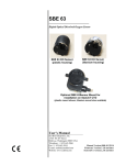
Shown below is a typical Hydro-DO shipment.
Hydro-DO
Optional sensor mount for
installation on SBE 19plus V2
Software, and Electronic Copies of
Software Manuals and User Manual
6
Hydro-DO
Manual revision 007
Section 2: Description of Hydro-DO
Hydro-DO
Section 2: Description of Hydro-DO
This section describes the functions and features of the Hydro-DO, including
specifications and dimensions.
System Description
The Hydro-DO is an easy-to-use, light, compact instrument ruggedly made of
titanium and other low-maintenance (plastic) materials, designed to be
incorporated into oceanographic sensing systems at depths up to 600 meters
(1960 feet). Commands sent to the Hydro-DO provide status display, data
acquisition setup, and diagnostic tests. Its data is telemetered by its internal, 3wire, RS-232C interface. The Hydro-DO has no sample memory or internal
batteries.
Hydro-DO
The Hydro-DO samples in two modes:
• Autonomous sampling –The Hydro-DO samples at pre-programmed
intervals of 1 to 32,767 seconds. It can be set to average up to
255 measurements per sample, and transmits the averaged data.
The Hydro-DO can be programmed to begin autonomous sampling when
power is applied or on command.
• Polled sampling – On command, the Hydro-DO takes one sample and
transmits the data.
The Hydro-DO outputs raw or converted (ASCII engineering units) data in
one of a number of formats, for compatibility with existing CTDs.
Each Hydro-DO is calibrated individually in a temperature-controlled bath.
Bath temperatures are varied at each of 4 oxygen values, providing a
comprehensive 24-point calibration. Two reference sensors in each bath are
standardized against Winkler titrations. Response time tests are conducted on
each sensor, using gas. Salinity and pressure impacts on sensor response are
each checked at two separate points.
The Hydro-DO is designed for use in a CTD's pumped flow path, providing
optimum correlation with CTD measurements. The elapsed time between the
CTD and associated oxygen measurement is easily quantified, and corrected
for in post-processing. The plumbing’s black tubing blocks light, reducing insitu algal growth.
Configuration options:
• With the optional sensor mount, the Hydro-DO can be plugged into the
RS-232 auxiliary sensor connector of the SBE 19plus V2 SeaCAT CTD.
• The Hydro-DO can be integrated into a HydroCAT.
7
Manual revision 007
Section 2: Description of Hydro-DO
Hydro-DO
The Hydro-DO is supplied with a powerful Windows software package,
Seasoft V2, which includes:
Notes:
• Help files provide detailed
information on the software.
• A separate software manual on CDROM contains detailed information
on the setup and use of Seasave V7
and SBE Data Processing.
• Sea-Bird supplies the current
version of our software when you
purchase an instrument. As software
revisions occur, we post the revised
software on our FTP site. See our
website (www.seabird.com) for the
latest software version number, a
description of the software changes,
and instructions for downloading the
software from the FTP site.
•
•
•
SeatermV2 - terminal program for communication and data retrieval.
SeatermV2 is a launcher, and launches the appropriate terminal program
for the selected instrument (Seaterm232 for RS-232 instruments such as
this Hydro-DO).
Seasave V7 – program for acquiring, converting, and displaying real-time
or archived raw data.
SBE Data Processing – program for calculation and plotting of
conductivity, temperature, pressure, auxiliary sensor data (such as
dissolved oxygen), and derived variables such as salinity and sound
velocity.
Specifications
Measurement
Range
120% of surface saturation in all natural waters,
fresh and salt
Initial Accuracy
Larger of ±3 µmol/kg (equivalent to 0.07 ml/L or 0.1 mg/L)
or ±2%
Resolution
0.2 µmol/kg
Sample-Based
Drift
< 1 µmol/kg / 100,000 samples (20 °C)
Response Time
τ
( , 63%
response)
< 6 sec (20 °C)
Sampling
Speed
1 Hz (1 sample/sec)
Calibration
Each sensor fully and individually calibrated
(0 – 450 µmol/kg oxygen, 0 – 30 °C, 0 – 35 psu,
0 – 2000 dbars)
8 coefficients plus 4 temperature compensation
coefficients
Input Power
6 - 24 VDC, 35 mA (0.08 J/sample)
Output Signal
RS-232, 600-115,200 baud (user-selectable),
8 data bits, no parity, 1 stop.
Depth rating,
housing, and
weight (in air)
Sensor:
600 m (1960 ft) plastic housing:
Optional sensor mount for use with
SBE 19plus V2:
8
245 g (0.54 lbs)
225 g (0.50 lbs)
Manual revision 007
Section 2: Description of Hydro-DO
Dimensions and Connector
Hydro-DO sensor for integration with HydroCAT
Hydro-DO sensor installed in
sensor mount, for use with RS-232
auxiliary sensor channel on CTD
(SBE 19plus V2 SeaCAT)
9
Hydro-DO
Manual revision 007
Section 3: Preparing Hydro-DO for Deployment
Hydro-DO
Section 3:
Preparing Hydro-DO for Deployment
This section describes installing software and testing power and
communications.
Software Installation
Notes:
• Help files provide detailed
information on the software.
• It is possible to use the Hydro-DO
without the SeatermV2 terminal
program by sending direct
commands from a dumb terminal or
terminal emulator, such as Windows
HyperTerminal.
• Sea-Bird supplies the current
version of our software when you
purchase an instrument. As software
revisions occur, we post the revised
software on our FTP site. See our
website (www.seabird.com) for the
latest software version number, a
description of the software changes,
and instructions for downloading the
software from the FTP site.
Seasoft V2 was designed to work with a PC running Windows XP service
pack 2 or later, Windows Vista, or Windows 7.
If not already installed, install SeatermV2 and other Sea-Bird software
programs on your computer using the supplied software CD:
1.
Insert the CD in your CD drive.
2.
Install software: Double click on SeasoftV2.exe. Follow the dialog box
directions to install the software. The installation program allows you to
install the desired components. Install all the components, or just install
SeatermV2, Seasave V7, and SBE Data Processing.
The default location for the software is c:\Program Files\Sea-Bird. Within that
folder is a sub-directory for each program.
Power and Communications Test
Note:
Hydro-DO integrated with a HydroCAT:
See the HydroCAT manual for
information on communicating with the
Hydro-DO through the HydroCAT.
The power and communications test will verify that the system works,
prior to deployment.
Test Setup
1.
Remove dummy plug (if applicable):
A. By hand, unscrew the locking sleeve from the Hydro-DO’s bulkhead
connector. If you must use a wrench or pliers, be careful not to
loosen the bulkhead connector instead of the locking sleeve.
B. Remove the dummy plug from the Hydro-DO’s I/O bulkhead
connector by pulling the plug firmly away from the connector.
2.
XSG Connector - Install the I/O cable connector, aligning the raised
bump on the side of the connector with the large pin (pin 1 - common) on
the Hydro-DO sensor mount. OR
MCBH Connector – Install the I/O cable connector, aligning the pins.
3.
Connect the I/O cable connector to your computer’s serial port.
4.
Connect the I/O cable connector’s red (+) and black (-) wires to a power
supply (6 – 24 VDC).
Locking sleeve
I/O cable
10
Manual revision 007
Section 3: Preparing Hydro-DO for Deployment
Hydro-DO
Test
1.
Double click on SeatermV2.exe. The main screen looks like this:
Notes:
• You can use any terminal
program to set up the Hydro-DO;
set it to 8 data bits, no parity,
1 stop bit, and 9600 baud (default
Hydro-DO baud rate).
Instructions here are for using
SeatermV2.
• See SeatermV2’s Help files.
SeatermV2 is a launcher. Depending on the instrument selected, it
launches Seaterm232 (RS-232 instruments), Seaterm485 (RS-485
instruments), or SeatermIM (inductive modem instruments).
Notes:
• The Hydro-DO is
based on Sea-Bird
Electronics’ SBE 63.
• See Seaterm232’s
Help files.
2.
In the Instruments menu, select SBE 63 Dissolved Oxygen Sensor.
Seaterm232 opens; the main screen looks like this:
Menus
Send Commands
Window
Command/Data Echo Area
Status Bar
Status –
Connecting,
Ready, etc.
•
•
•
•
Capture
status
Menus – For tasks and frequently executed instrument commands.
Send Commands window – Contains commands applicable to your
Hydro-DO. The list appears after you connect to the Hydro-DO.
Command/Data Echo Area – Title bar of this window shows
Seaterm232’s current comm port and baud rate. Commands and the
Hydro-DO responses are echoed here. Additionally, a command can
be manually typed or pasted (ctrl + V) here. Note that the Hydro-DO
must be connected and awake for it to respond to a command.
Status bar – Provides connection, script, and capture status
information.
11
Manual revision 007
Section 3: Preparing Hydro-DO for Deployment
Hydro-DO
Following is a description of the menus:
Menu
Description
Equivalent Command*
• Load command file – opens selected .XML
command file, and fills Send Commands
window with commands
File
—
• Unload command file – closes command
file, and removes commands from Send
Commands window
• Exit - Exit program.
• Connect – connect to comm port
• Disconnect – disconnect from
comm port
Communications • Configure – Establish communication
—
parameters (comm port and baud rate).
• Disconnect and reconnect – may be useful
if Hydro-DO has stopped responding
• Abort – interrupt and stop Hydro-DO
• (press Esc key)
response
• Send stop command
• Stop
Command
Remaining menu items are not applicable to
Hydro-DO
Capture Hydro-DO responses on screen to
file, to save real-time data or use for
Capture
diagnostics. File has .cap extension.
—
Click Capture again to turn off capture.
Capture status displays in Status bar.
Upload
Not applicable to Hydro-DO
—
• Diagnostics log - Keep a diagnostics log.
• Convert .XML data file – not applicable to
Hydro-DO
Tools
—
• Send script – Send XML script to
Hydro-DO. May be useful if you have a
number of Hydro-DOs to program with
same setup.
*See Command Descriptions in Section 4: Deploying and Operating
Hydro-DO.
12
Manual revision 007
Section 3: Preparing Hydro-DO for Deployment
3.
Hydro-DO
If this is the first time Seaterm232 is being used, the Serial Port
Configuration dialog box displays:
Computer COM port and baud rate for
communication between computer and
Hydro-DO. Seaterm232 tries to connect at
this baud rate, but if unsuccessful will
cycle through all available baud rates.
Update COM Port pulldown to
include connected USB ports.
Make the desired selections, and click OK.
Note:
Seaterm232’s baud rate must be the
same as the Hydro-DO baud rate (set
with SetBaud=). Baud is factory-set
to 9600, but can be changed by the
user (see Command Descriptions in
Section 4: Deploying and Operating
Hydro-DO). Other communication
parameters – 8 data bits, 1 stop bit,
and no parity – cannot be changed.
4.
Seaterm232 tries to automatically connect to the Hydro-DO. As it
connects, it sends GetHD and displays the response, which provides
factory-set data such as instrument type, serial number, and firmware
version. Seaterm232 also fills the Send Commands window with the
correct list of commands for your Hydro-DO.
If there is no communication:
A. In the Communications menu, select Configure. The Serial Port
Configuration dialog box appears. Select the Comm port and baud
rate for communication, and click OK. Note that the factory-set baud
rate is documented on the Configuration Sheet. .
B. In the Communications menu, select Connect (if Connect is grayed
out, select Disconnect and reconnect). Seaterm232 will attempt to
connect at the baud specified in Step A, but if unsuccessful will then
cycle through all other available baud rates.
C. If there is still no communication, check cabling between the
computer and Hydro-DO, and try to connect again.
D. If there is still no communication, repeat Step A with a different
comm port, and try to connect again.
After Seaterm232 displays the GetHD response, it provides an S> prompt
to indicate it is ready for the next command.
13
Manual revision 007
Section 3: Preparing Hydro-DO for Deployment
Note:
The Command list says
SBE 63 Commands because the
Hydro-DO is based on Sea-Bird
Electronics’ SBE 63.
Hydro-DO
Taking a look at the Send Commands window:
Click on desired command
description in list.
Help box describes
selected command in more
detail.
Enter any command
arguments (such as
desired output format) in
this box.
Click Execute when ready
to send selected
command.
This box
shows selected
command.
You can use the Send Commands window to send commands, or simply type
the commands in the Command/Data Echo area if desired.
14
Manual revision 007
Notes:
The GetHD response outputs
SBE063 as the device type
because the Hydro-DO is based
on Sea-Bird Electronics’ SBE 63.
The serial number is xxxx, where
xxxx is the last 4 digits of the
serial number on the Hydro-DO’s
label (for example, HDO-50013 on
the label appears as 0013 in the
GetHD response.
Section 3: Preparing Hydro-DO for Deployment
5.
Hydro-DO
Display Hydro-DO setup and hardware information by typing GetHD and
pressing the Enter key. The display looks like this:
<HardwareData DeviceType = 'SBE063' SerialNumber = '0013'>
<Manufacturer>Sea-Bird Electronics, Inc.</Manufacturer>
<FirmwareVersion>3.101</FirmwareVersion>
<FirmwareDate>May 14 2013 10:37:51</FirmwareDate>
<CommandSetVersion>1.3</CommandSetVersion>
<MFGDate>04850</MFGDate>
<PCBAssembly>41755</PCBAssembly>
<PCBSerialNum>56556</PCBSerialNum>
<PCBAssembly>41756</PCBAssembly>
<PCBSerialNum>57151</PCBSerialNum>
<FilmSerialNum>00077</FilmSerialNum>
<Supply Voltage>8.63</Supply Voltage>
<LoaderVersion>SBE 63 FirmwareLoader V 1.0</LoaderVersion>
<CalibrationDate>04861</CalibrationDate>
<HardwareConfig>
<BaudRate>009600</BaudRate>
<BlueOnTime>0000000</BlueOnTime>
<SampleAvg>002</SampleAvg>
<SampleInterval>00004</SampleInterval>
<BootDelay>001</BootDelay>
<OutFormat>01</OutFormat>
<AnalogGain>2</AnalogGain>
<AnalogOffset>00</AnalogOffset>
<AutoRun>0</AutoRun>
<BlueTupdate>0</BlueTupdate>
<SerPause>1</SerPause>
<Echo>1</Echo>
<TxPwrSave>0</TxPwrSave>
<Flags>0x0023</Flags>
</HardwareConfig>
</HardwareData>
6.
Command the Hydro-DO to take a sample by typing TS and pressing the
Enter key. The display looks like this (if Hydro-DO is set up with
SetFormat=1):
16.411,0.550736,5.980,25.0011
where
16.411 = raw phase delay
0.550736 = raw thermistor voltage
5.980 = converted oxygen in ml/l
25.0011 = temperature in deg C
The Hydro-DO is ready for programming and deployment.
15
Manual revision 007
Section 4: Deploying and Operating Hydro-DO
Hydro-DO
Section 4:
Deploying and Operating Hydro-DO
This section provides instructions for deploying the Hydro-DO. It includes:
Note:
Separate software manuals and
Help files contain detailed
information on installation, setup,
and use of Sea-Bird’s software.
•
•
•
•
•
Sampling modes, including example sets of commands
Command descriptions
Data output formats
Deployment
Recovery
Sampling Modes
Notes:
• Sea-Bird ships the Hydro-DO with
SetAutoRun=0 (it will not
automatically start sampling when
power is applied). If you previously
sent SetAutoRun=1 (it
automatically started sampling
when power was applied), press the
Esc key to stop sampling. You will
then be able to send commands to
change the setup.
• Hydro-DO response to commands
is not shown in examples.
The Hydro-DO has two sampling modes for obtaining data:
• Polled Sampling
• Autonomous Sampling
Shown below are descriptions and examples of the two sampling modes. Note
that the Hydro-DO’s response to each command is not shown in the examples.
Review the operation of the sampling modes and the commands described in
Command Descriptions before setting up your system.
Polled Sampling
On command (TS or TSR), the Hydro-DO takes one sample of data and
transmits the data.
Example 1: Polled Sampling (user input in bold).
Set up to wait for a command upon power up (SetAutoRun=0). Set up to
echo commands (SetEcho=1), output converted oxygen and temperature
data (SetFormat=0), and average 2 measurements/sample (SetAvg=2).
Verify setup with status (GetHD) command. Remove power.
(Apply power, then select Connect in Seaterm232’s Communications
menu to connect and wake up.)
S>SETAUTORUN=0
S>SETECHO=1
S>SETFORMAT=0
S>SETAVG=2
S>GETHD (to verify setup)
(Remove power.)
When ready to take a sample (repeat as desired): apply power, establish
communications with Hydro-DO, command it to take a sample and
output data in format established with SetFormat=, and remove power.
(Apply power, then select Connect in Seaterm232’s Communications
menu to connect and wake up.)
(Before first sample, click Capture menu to capture data to a file –
Seaterm232 requests file name for data to be stored.)
S>TS
(Remove power.)
Examples continued on next page
16
Manual revision 007
Note:
When using the Hydro-DO with an
SBE 19plus V2 CTD, the following
setup in the Hydro-DO is required:
• SetBaud= to the baud rate set in the
CTD
• SetEcho=1
• SetFormat=1
• SetAvg=1 to 16; recommended
value is 2
• SetAutoRun=0
In the 19plus V2, if it is set to moored
mode (MM), set:
• Pump mode to 2
(MooredPumpMode=2).
• Delay before sampling
(DelayBeforeSampling=) to
25 sec at 15 °C to 40 sec at 0 °C
(linear interpolation between those
values). This provides enough time
for the Hydro-DO to equilibrate after
pumping begins, before the
measurement is made.
In the CTD, the interval between
samples (SampleInterval=) must be
greater than or equal to the sum of the
times required to sample. Total time is
affected by the following:
- Minimum time required for CTD to
take a sample (≈ 2.5 sec).
- Time required for CTD to take and
average NCycles= samples; samples
are taken 0.25 sec apart.
- Delay after providing power to
external sensors before sampling
(DelayBeforeSampling=); described
above.
- Delay after sampling before turning
off power to external sensors
(DelayAfterSampling=).
Section 4: Deploying and Operating Hydro-DO
Hydro-DO
Example 2: Polled Sampling with SBE 19plus V2 (user input in bold).
Set up to wait for a command upon power up (SetAutoRun=0). Set up to
echo commands (SetEcho=1), average 2 measurements per output sample
(SetAvg=2), and output data in a format compatible with 19plus V2
(SetFormat=1). Set Hydro-DO baud rate to same baud as 19plus V2
(assume 9600 baud for this example). Verify setup with status (GetHD)
command. Remove power.
(Apply power to Hydro-DO, then select Connect in Seaterm232’s
Communications menu to connect to and wake up Hydro-DO.)
S>SETAUTORUN=0
S>SETECHO=1
S>SETAVG=2
S>SETFORMAT=1
S>SETBAUD=9600
(get message to re-enter baud)
S>SETBAUD=9600
(In Seaterm232’s Communications menu, select Configure. Change baud
to 9600 and click OK. In Seaterm232’s Communications menu, select
disconnect and reconnect. You will now be communicating at new baud).
S>GETHD
(to verify setup)
(Remove power from Hydro-DO.)
When ready to begin sampling: Connect Hydro-DO to 19plus V2 RS-232
auxiliary sensor connector. Set 19plus V2 to moored mode (MM) and set
the sampling interval (SampleInterval=) Start autonomous sampling in
19plus V2 (see 19plus V2 manual). Each time SBE 19plus V2 takes a
measurement, it applies power to and requests a sample from Hydro-DO
using TS command.
When ready to stop sampling: Stop autonomous sampling in 19plus V2.
17
Manual revision 007
Section 4: Deploying and Operating Hydro-DO
Hydro-DO
Autonomous Sampling
The Hydro-DO does not have an internal (standby) real-time clock. Therefore,
once you start autonomous sampling, power to the Hydro-DO must remain on
for autonomous sampling to continue at the specified interval.
SetAutoRun defines how sampling starts:
Note:
Sea-Bird ships the Hydro-DO with
SetAutoRun=0 (it will not
automatically start sampling when
power is applied). If you send
SetAutoRun=1, turn power off and
then on again to start sampling, or
send Start.
SetAutoRun=
0 (default)
1
To Start
Autonomous
Sampling
Send Start.
To Stop Autonomous Sampling
• Turn off power, or
• Click Esc (stopping this way allows
you to then send commands to
check/modify the setup), or
Turn on power.
• Send Stop (stopping this way allows
you to then send commands to
check/modify the setup).
Example 1: Autonomous Sampling Setup for SetAutoRun=0
(user input in bold).
Set up to wait for a command upon power up (SetAutoRun=0).
Set up to echo commands (SetEcho=1), take and output a sample every
10 sec (SetInterval=10), averaging 2 measurements per output sample
(SetAvg=2), and output converted oxygen and temperature data
(SetFormat=0). Verify setup with status (GetHD) command. Remove
power.
(Apply power, then select Connect in Seaterm232’s Communications
menu to connect and wake up.)
S>SETAUTORUN=0
S>SETECHO=1
S>SETINTERVAL=10
S>SETAVG=2
S>SETFORMAT=0
S>GETHD
(to verify setup)
(Remove power.)
When ready to begin sampling:
(Apply power, then select Connect in Seaterm232’s Communications
menu to connect and wake up.)
S>START
When ready to stop sampling:
(Send Stop, click Esc, or remove power.)
Examples continued on next page
18
Manual revision 007
Section 4: Deploying and Operating Hydro-DO
Hydro-DO
Example 2: Autonomous Sampling Setup for SetAutoRun=1 for use
with power supply and logger.
Set up to start sampling when power is applied (SetAutoRun=1).
Set up to echo commands (SetEcho=1), take samples at 10-sec intervals
(SetInterval=10), average 2 measurements per output sample
(SetAvg=2), output converted oxygen and temperature data
(SetFormat=0), and set the delay before sampling to the minimum value
(SetBootDelay=). Verify setup with status (GetHD) command. Remove
power.
(Apply power, then select Connect in Seaterm232’s Communications
menu to connect and wake up.)
S>SETAUTORUN=1
S>SETECHO=1
S>SETINTERVAL=10
S>SETAVG=2
S>SETFORMAT=0
S>SETBOOTDELAY=1
S>GETHD
(to verify setup)
(Remove power from Hydro-DO.)
When ready to begin sampling, connect Hydro-DO to power supply and
data logger.
(Apply power – Hydro-DO automatically begins sampling at 10-sec
intervals.)
When ready to stop sampling:
(remove power.)
19
Manual revision 007
Section 4: Deploying and Operating Hydro-DO
Hydro-DO
Command Descriptions
This section describes commands and provides sample outputs.
See Appendix III: Command Summary for a summarized command list.
When entering commands:
•
Input commands to the Hydro-DO in upper or lower case letters and
register commands by pressing the Enter key (0xD).
•
Commands to enable a parameter can be entered with the argument as
Y or 1 for yes, and N or 0 for no (for example, SetAutoRun=y and
SetAutoRun=1 are equivalent; both enable automatic starting of sampling
when power is applied).
•
The Hydro-DO sends Command failed: Unknown command
if an invalid command is entered.
•
If the Hydro-DO does not return an S> prompt after executing a
command, press the Enter or Esc key to get the S> prompt.
•
If the Hydro-DO is transmitting data and you want to stop it, press the Esc
key or send Stop. Alternatively, remove power.
•
All commands that change setup take effect immediately, and are
committed to nonvolatile storage (Hydro-DO retains settings when power
is removed).
20
Manual revision 007
Section 4: Deploying and Operating Hydro-DO
Hydro-DO
Status Command
Notes:
• All Status command responses
output SBE063 as the device type
because the Hydro-DO is based on
Sea-Bird Electronics’ SBE 63.
• The serial number in the status
responses is xxxx, where xxxx is
the last 4 digits of the serial number
on the Hydro-DO’s label (for
example, HDO-50013 on the label
appears as 0013 in the status
responses.
GetSD
Get and display status data, which includes
all parameters related to setup that can be
input/modified. Many parameters are not
user-programmable (programmed at
factory). List and example include
commands used to modify userprogrammable parameters:
•
•
•
•
•
•
•
•
•
•
•
•
•
•
•
•
•
•
•
Instrument type and serial number
Firmware version
Firmware date
Command set version
Software used to upload firmware to
Hydro-DO
Calibration date (days since 1/1/2000)
Communication baud rate [SetBaud=]
Blue LED counter total on-time (sec)
Number of measurements to average per
sample [SetAvg=]
Interval between samples for autonomous
sampling [SetInterval=]
Delay before sampling after power is
applied [SetBootDelay=]
Data output format [SetFormat=]
Analog gain and offset
Begin sampling automatically when power
applied [SetAutoRun=]?
Update Blue LED counter with every
sample?
Serial pause (factory set; must be 1 for use
with SBE 19plus V2 in Profiling mode;
can be 0 or 1 for other applications).
Enable echoing [SetEcho=]?
Power save mode, 0 or 1 (factory set; 0 for
all applications)
Internally calculated [based on settings]
Example: (user input in bold)
S>getsd
<StatusData DeviceType = 'SBE063' SerialNumber = '0013'>
<FirmwareVersion>3.1.0</FirmwareVersion>
<FirmwareDate>May 14 2013 10:37:51</FirmwareDate>
<CommandSetVersion>1.3</CommandSetVersion>
<LoaderVersion>SBE 63 FirmwareLoader V 1.0</LoaderVersion>
<CalibrationDate>04861</CalibrationDate>
<StatusConfig>
<BaudRate>009600</BaudRate>
[SetBaud=]
<BlueOnTime>0000000</BlueOnTime>
<SampleAvg>002</SampleAvg>
[SetAvg=]
<SampleInterval>00004</SampleInterval>
[SetInterval=]
<BootDelay>001</BootDelay>
[SetBootDelay=]
<OutFormat>01</OutFormat>
[SetFormat=]
<AnalogGain>2</AnalogGain>
<AnalogOffset>00</AnalogOffset>
<AutoRun>0</AutoRun>
[SetAutoRun=]
<BlueTupdate>0</BlueTupdate>
<SerPause>1</SerPause>
<Echo>1</Echo>
[SetEcho=]
<TxPwrSave>0</TxPwrSave>
<Flags>0x0023</Flags>
[internally calculated, based on SetAutoRun= and factory settings]
</StatusConfig>
</StatusData>
21
Manual revision 007
Section 4: Deploying and Operating Hydro-DO
Hydro-DO
Status Command (continued)
GetHD
Get and display hardware data. Many
parameters are not user-programmable,
and are programmed at the factory. List
and example include commands used to
modify user-programmable parameters:
•
•
•
•
•
•
•
•
•
•
Instrument type and serial number
Manufacturer
Firmware version
Firmware date
Command set version
Manufacture date (days since 1/1/2000)
PCB assemblies and serial numbers
Optical film serial number
Power supply voltage seen by Hydro-DO
Software used to upload firmware to
Hydro-DO
•
•
•
•
•
•
•
•
•
•
•
•
•
•
22
Calibration date (days since 1/1/2000)
Communication baud [SetBaud=]
Blue LED counter total on-time (sec)
Number of measurements to average per
sample [SetAvg=]
Interval between samples for autonomous
sampling [SetInterval=]
Delay before sampling after power is
applied [SetBootDelay=]
Data output format [SetFormat=]
Analog gain and offset
Begin sampling automatically when power
applied [SetAutoRun=]?
Update Blue LED counter with each sample?
Serial pause (factory set; must be 1 for use
with SBE 19plus V2 in Profiling mode;
can be 0 or 1 for other integrations).
Enable echoing [SetEcho=]?
Power save mode, 0 or 1 (factory set; 0 for
all applications)
Internally calculated [based on settings]
Manual revision 007
Section 4: Deploying and Operating Hydro-DO
Hydro-DO
Example: (user input in bold)
S>gethd
<HardwareData DeviceType = 'SBE063' SerialNumber = '0013'>
<Manufacturer>Sea-Bird Electronics, Inc.</Manufacturer>
<FirmwareVersion>3.1.0</FirmwareVersion>
<FirmwareDate>May 14 2013 10:37:51</FirmwareDate>
<CommandSetVersion>1.3</CommandSetVersion>
<MFGDate>04850</MFGDate>
<PCBAssembly>41755</PCBAssembly>
<PCBSerialNum>56556</PCBSerialNum>
<PCBAssembly>41756</PCBAssembly>
<PCBSerialNum>57151</PCBSerialNum>
<FilmSerialNum>00077</FilmSerialNum>
<Supply Voltage>8.63</Supply Voltage>
<LoaderVersion>SBE 63 FirmwareLoader V 1.0</LoaderVersion>
<CalibrationDate>04861</CalibrationDate>
<HardwareConfig>
<BaudRate>009600</BaudRate>
<BlueOnTime>0000000</BlueOnTime>
<SampleAvg>002</SampleAvg>
<SampleInterval>00004</SampleInterval>
<BootDelay>001</BootDelay>
<OutFormat>01</OutFormat>
<AnalogGain>2</AnalogGain>
<AnalogOffset>00</AnalogOffset>
<AutoRun>0</AutoRun>
<BlueTupdate>0</BlueTupdate>
<SerPause>1</SerPause>
<Echo>1</Echo>
[SetBaud=]
[SetAvg=]
[SetInterval=]
[SetBootDelay=]
[SetFormat=]
[SetAutoRun=]
[SetEcho=]
<TxPwrSave>0</TxPwrSave>
[internally calculated, based on SetAutoRun= and factory settings]
<Flags>0x0023</Flags>
</HardwareConfig>
</HardwareData>
23
Manual revision 007
Section 4: Deploying and Operating Hydro-DO
Hydro-DO
Status Command (continued)
GetCC
Get and display calibration coefficients,
which are initially factory-set and should
agree with Calibration Certificate shipped
with Hydro-DO. Example below includes,
where applicable, command used to
modify parameter.
• <CalDate> is number of days since
January 1, 2000.
• SetRefSal= and SetRefP= are set by
user; see description below in
Calibration Coefficients section of
these command descriptions
Example: (user input in bold)
S>getcc
<CalibrationCoefficients DeviceType = 'SBE063' SerialNumber = '0013'>
<Calibration format = 'TEMP1' id = 'Temperature'>
<SerialNum>06300013</SerialNum>
<CalDate>04861</CalDate>
<TA0>+5.593530e-04</TA0>
<TA1>+2.756939e-04</TA1>
<TA2>-1.453041e-06</TA2>
<TA3>+1.535286e-07</TA3>
</Calibration>
<Calibration format = 'OX1' id = 'OptOxygen'>
<SerialNum>06300013</SerialNum>
<CalDate>04861/CalDate>
<A0>+8.900000e-01</A0>
<A1>-1.520000e-03</A1>
<A2>+0.000000e+00</A2>
<B0>-1.820000e-01</B0>
<B1>+1.086300e+00</B1>
<C0>+1.737200e-01</C0>
<C1>+6.545500e-03</C1>
<C2>+8.945700e-05</C2>
<E>-2.600000e-03</E>
<SOLB0>-6.245230e-03</SOLB0>
<SOLB1>-7.376141e-03</SOLB1>
<SOLB2>-1.034100e-02</SOLB2>
<SOLB3>-8.170830e-03</SOLB3>
<SOLC0>-4.886820e-07</SOLC0>
<REFSALpsu>+0.000000e+00</REFSALpsu>
<REFPRESSdbar>+0.000000e+00</REFPRESSdbar>
</Calibration>
</CalibrationCoefficients>
24
[SetTA0=]
[SetTA1=]
[SetTA2=]
[SetTA3=]
[SetA0=]
[SetA1=]
[SetA2=]
[SetB0=]
[SetB1=]
[SetC0=]
[SetC1=]
[SetC2=]
[SetE=]
[SetSolB0=]
[SetSolB1=]
[SetSolB2=]
[SetSolB3=]
[SetSolC0=]
[SetRefSal=]
[SetRefP=]
Manual revision 007
Section 4: Deploying and Operating Hydro-DO
Hydro-DO
Status Command (continued)
DS
Get and display status data in non-XML
format. Many parameters are not userprogrammable, and are programmed at the
factory. List and example include
commands used to modify userprogrammable parameters:
•
•
•
•
•
•
•
•
•
•
•
•
•
•
•
•
•
•
•
•
•
•
•
25
Instrument type
Instrument serial number
PCB assemblies and serial numbers
Optical film serial number
Firmware version and date
Software used to upload firmware to
Hydro-DO
Manufacturing date (days since 1/1/2000)
Calibration date (days since 1/1/2000)
Power supply voltage seen by Hydro-DO
Communication baud rate [SetBaud=]
Analog gain
Analog offset
Blue LED counter total on-time (sec)
Number of measurements to average per
sample [SetAvg=]
Interval between samples for autonomous
sampling [SetInterval=]
Delay before sampling after power is
applied [SetBootDelay=]
Data output format [SetFormat=]
Begin sampling automatically when power
applied [SetAutoRun=]?
Update Blue LED counter with every
sample?
Serial pause (factory set; must be 1 for use
with SBE 19plus V2 in Profiling mode;
can be 0 or 1 for other applications).
Enable echoing [SetEcho=]?
Power save mode, 0 or 1 (factory set; 0 for
all applications)
Internally calculated [based on settings]
Manual revision 007
Section 4: Deploying and Operating Hydro-DO
Hydro-DO
Example: (user input in bold)
S>ds
Model
Serial#
PCBID Analog
PCBID Digital
Sensor Film Serial#
Firmware Rev
Firmware Loader Ver
MFG days +1/1/2000
CAL days +1/1/2000
Supply Voltage
Baudrate
Analog Gain
Analog Offset
Blue On-time [sec]
Samples Averaged
Sample Intvl [sec]
Boot Delay [sec]
Output format
Autorun [0/1]
BlueTUpdate [0/1]
SerPause [0/1]
Echo [0/1]
TxPwrsave [0/1]
Flags
=
=
=
=
=
=
=
=
=
=
=
=
=
=
=
=
=
=
=
=
=
=
=
=
SBE63 rev J
0442
41755 SN56556
41756 SN57151
00077
3.1.0 May 14 2013 10:37:51
SBE 63 FirmwareLoader V 1.0
4850
4861
8.29
9600
[SetBaud=]
02
00
00
02
[SetAvg=]
0004
[SetInterval=]
001
[SetBootDelay=]
01
[SetFormat=]
0
[SetAutoRun=]
0
1
1
[SetEcho=]
0
0x23
[internally calculated, based on SetAutoRun= and factory settings]
26
Manual revision 007
Section 4: Deploying and Operating Hydro-DO
Hydro-DO
Setup Commands
Note:
When communicating directly with the
Hydro-DO, the Hydro-DO’s baud rate
(set with SetBaud=) must be the same
as Seaterm232’s baud rate (set in the
Communications menu).
Note:
When using the Hydro-DO with an
SBE 19plus V2 CTD, the following
setup in the Hydro-DO is required:
• SetBaud= to the baud rate set in the
CTD
• SetEcho=1
• SetFormat=1
• SetAvg=1 to 16; recommended
value is 2
• SetAutoRun=0
In the CTD, set:
• Pump mode to 2 (PumpMode=2).
• Delay before sampling
(DelayBeforeSampling=) to
25 sec at 15 °C to 40 sec at 0 °C
(linear interpolation between those
values). This provides enough time
for the Hydro-DO to equilibrate after
pumping begins, before the
measurement is made.
In the CTD, the interval between
samples (SampleInterval=) must be
greater than or equal to the sum of the
times required to sample. Total time is
affected by the following:
- Minimum time required for CTD to
take a sample (≈ 2.5 sec).
- Time required for integration of
optional Quartz pressure sensor
(ParosIntegration=).
- Time required for CTD to take and
average NCycles= samples; samples
are taken 0.25 sec apart.
- Delay after providing power to
external sensors before sampling
(DelayBeforeSampling=); described
above.
- Delay after sampling before turning
off power to external sensors
(DelayAfterSampling=).
SetBaud=x
x= baud rate (600, 1200, 2400, 4800,
9600, 19200, 33600, 38400, 57600, or
115200). Default 9600. Check capability
of your computer and terminal program
before increasing baud rate; high baud
rates require a short cable and good PC
serial port with accurate clock. Hydro-DO
requires you to enter command twice to
confirm.
Example: (user input in bold).
S>setbaud=19200
Baud change requested.
Re-enter setbaud command at OLD baudrate to confirm
S>setbaud=19200
(may then show garbage characters, because of baud rate change)
(In Seaterm232’s Communications menu, select Configure. Change baud to 19200 and
click OK. In Seaterm232’s Communications menu, select Disconnect and reconnect).
S>
(now communicating at 19200 baud)
SetEcho=x
x=1: Echo characters received from
computer; monitor shows entered
commands as you type. Provides
compatibility with SeaCATs
(SBE 19plus V2), and HydroCATs.
Default.
x=0: Do not.
SetFormat=x
Data output format (see Data Formats for
details):
x=0: Converted oxygen and temperature
(with units).
x=1: Raw phase delay and thermistor
voltage, converted oxygen and
temperature (no units), for compatibility
with SeaCATs (19plus V2), and
HydroCATs. Default.
x=2: Raw and converted data.
x=3: Instrument name, serial number, and
converted oxygen.
SetBootDelay=x
x= delay after power is applied before
sampling (1 - 255 sec). Default 1. Only
applicable if AutoRun=1.
SetInterval=x
x= interval between samples
(1 – 32,767 sec) for autonomous sampling
(if power remains on, and Start has been
sent or AutoRun=1). Default 4.
27
Manual revision 007
Section 4: Deploying and Operating Hydro-DO
Hydro-DO
Setup Commands (continued)
Note:
If more time is required than provided
by SetInterval (can only occur if
SetInterval is small and SetAvg is
large), the sample is delayed until all
the measurements defined by SetAvg
are completed.
Note:
To start autonomous sampling after
you send SetAutoRun=1:
• turn power off and then on again, or
• send Start or Go
SetAvg=x
x = number of measurements to take and
average per sample (1–64, or 1–32 for 1Hz
sampling); default 2. Each additional
measurement adds approximately
0.0167 sec. Increasing SetAvg= shortens
sensor film life and increases photobleaching effects. Sea-Bird recommends
SetAvg=2 for best results, to prevent
calibration shifts caused by film heating
and photo bleaching-effects.
SetAutoRun=x
x=0: Wait for command when power
applied. Default. Required setting for use
with SeaCATs (19plus V2), and
HydroCATs.
x=1: Begin sampling when power applied.
First sample taken after SetBootDelay=.
*Default
Reset most Setup parameters to their
factory defaults (SetEcho=1,
SetFormat=1, SetBootDelay=1,
SetInterval=4, SetAvg=2,
SetAutoRun=0). Baud (SetBaud=) is not
reset.Also resets factory-set parameters
SerPause (0), BlueTUpdate (0),
TxPwrSave (0), Gain (2), and Offset (0).
Sampling Commands
Start or Go
Start autonomous sampling immediately at
rate set by SetInterval=, and output data
in format defined by SetFormat=.
Applicable if:
• SetAutoRun=0, or
• SetAutoRun=1, and you previously
clicked Esc to stop sampling.
To stop sampling:
• Click Esc or send Stop command.
Once sampling is stopped and
terminal program shows S> prompt,
you can send desired commands
(setup, status, etc.).
OR
• Remove power.
Stop
Stop autonomous sampling. Command
will not be echoed while autonomous
sampling. S> prompt appears to signal that
autonomous sampling has stopped.
TS
Take 1 sample and transmit data in format
defined by SetFormat=.
TSR
Take 1 sample and transmit data in raw
format (for factory diagnostics).
Note:
You may need to click Esc or send
Stop several times to get the HydroDO to respond.
28
Manual revision 007
Section 4: Deploying and Operating Hydro-DO
Hydro-DO
Calibration Coefficients Commands
With the exception of SetRefSal= and SetRefP=, calibration coefficients are
initially factory-set and should agree with Calibration Certificate shipped with
the Hydro-DO.
Note:
S = integer
F = floating point number
SetCalDate=S
S= calibration date (days since
January 1, 2000).
SetTA0=F
F= TA0 coefficient.
SetTA1=F
F= TA1 coefficient.
SetTA2=F
F= TA2 coefficient.
SetTA3=F
F= TA3 coefficient.
SetA0=F
F= A0 coefficient.
SetA1=F
F= A1 coefficient.
SetA2=F
F= A2 coefficient.
SetB0=F
F= B0 coefficient.
SetB1=F
F= B1 coefficient.
SetC0=F
F= C0 coefficient.
SetC1=F
F= C1 coefficient.
SetC2=F
F= C2 coefficient.
SetE=F
F= E coefficient.
SetSolB0=F
F= SolB0 coefficient.
SetSolB1=F
F= SolB1 coefficient.
SetSolB2=F
F= SolB2 coefficient.
SetSolB3=F
F= SolB3 coefficient.
SetSolC0=F
F= SolC0 coefficient.
SetRefSal=F
F= Reference salinity (psu) to use for
oxygen calculation in converted units.
Default 0.
For moored application, enter approximate
value expected for deployment. For
profiling applications, enter 0, and correct
oxygen for salinity effect in postprocessing.
SetRefP=F
F= Reference pressure (decibars) to use
for oxygen calculation in converted units.
Default 0.
For moored application, enter value
expected for deployment.
For profiling applications, enter 0, and
correct oxygen for pressure effect in postprocessing.
29
Manual revision 007
Section 4: Deploying and Operating Hydro-DO
Hydro-DO
Data Formats
Note about units for converted oxygen:
Sea-Bird uses the following equations to convert oxygen to various
engineering units:
[mg/L] = [ml/L] * 1.42903
[micromole/Kg] = [ml/L] * 44660 / (sigma_theta(P,T,S) + 1000)
For the micromole/Kg conversion, there is disagreement in the scientific
community about the conversion constant 44660:
• The value 44660 is exact for oxygen gas.
• The value 44615 is the average value for atmospheric gas
(N2,O2,Ar,H2O,CO2,...). It is not exact for any individual gas, but has
been used historically by oceanographers.
The argument distills to exact versus historic, with oceanographers split;
Sea-Bird uses 44660 in all software calculations.
Notes:
• Each scan of data ends with a
carriage return and line feed.
• Converted oxygen values (dissolved
oxygen in ml/l) are dependent on the
user-set SetRefSal= and SetRefP=.
• See Appendix I: Functional
Description for details on the
calibration equation and conversion
of the raw data to dissolved oxygen
in ml/l.
Following are the data formats:
•
SetFormat=0 – Converted oxygen and temperature with units:
o.oooo ml/l, tt.tttt C
where
o.oooo = dissolved oxygen in ml/l
tt.tttt = temperature in deg C
Example: SetFormat=0
4.3019 ml/l, 25.2556 C
(converted oxygen, converted temperature)
•
SetFormat=1 (default) –SeaCAT (19plus V2) and HydroCAT:
aa.aaa, b.bbbbbb, o.oooo, tt.tttt where
aa.aaaa = raw phase delay (µsec)
b.bbbb = raw thermistor voltage
o.ooo = dissolved oxygen in ml/l
tt.tttt = temperature in deg C
Example: SetFormat=1
16.6423,0.641321,4.308,25.2553
(raw phase delay, raw thermistor voltage, converted oxygen, converted
temperature)
30
Manual revision 007
Section 4: Deploying and Operating Hydro-DO
•
Hydro-DO
SetFormat=2 – Raw and converted data:
01/01/11 00:00:00 660 aaaaa 695 bbbbb 570
where
aaaaa = raw phase delay (x1000)
bbbbb = raw thermistor voltage (x65536/3.30)
oooo = dissolved oxygen in ml/l (x1000)
ttttt = temperature in deg C (x1000)
Italic numbers are constants, not used in calculations
Each field is separated by a tab character.
Example: SetFormat=2
01/01/11
00:00:00
695
12736
25255
660
570
oooo
ttttt
16649
4303
(information in italics are constants not used in calculations; remaining
information is raw phase delay x1000, raw thermistor voltage x1000, converted
oxygen x1000, converted temperature x1000)
•
Note:
The Hydro-DO outputs SBE63 as the
device type because the Hydro-DO
is based on Sea-Bird Electronics’
SBE 63. The serial number is xxxx,
where xxxx is the last 4 digits of the
serial number on the Hydro-DO’s
label (for example, HDO-50013 on
the label appears as 0013 in the data.
SetFormat=3 – Instrument name, serial number, and converted oxygen:
SBE63
ssss
oo.ooo
where
ssss = Hydro-DO serial number
oo.ooo = dissolved oxygen in ml/l (leading zero is not suppressed)
Hydro-DO and serial number are separated by a tab character; serial
number and dissolved oxygen are separated by two tab characters.
Example: SetFormat=3
SBE63
0013
(serial number, converted oxygen in ml/l)
31
04.304
Manual revision 007
Section 4: Deploying and Operating Hydro-DO
Hydro-DO
Deployment
Note:
In the 19plus V2, if it is set to moored
mode (MM), set:
• Pump mode to 2
(MooredPumpMode=2).
• Delay before sampling
(DelayBeforeSampling=) to 25 sec
at 15 °C, 40 sec at 0 °C (linear
interpolation between those values).
This provides enough time for the
Hydro-DO to equilibrate after
pumping begins, before the
measurement.
In the CTD, the interval between
samples (SampleInterval=) must be
> sum of times required to sample.
Total time is affected by:
- Minimum time for CTD to take
sample (≈ 2.5 sec).
- Time for CTD to take and average
NCycles= samples, taken 0.25 sec
apart.
- Delay after providing power to
external sensors before sampling
(DelayBeforeSampling=); described
above.
- Delay after sampling before turning
off power to external sensors
(DelayAfterSampling=).
Integration with SeaCAT CTD (SBE 19plus V2)
Prior to installing the Hydro-DO on the CTD, verify that the Hydro-DO is set
up as follows (see Section 3: Preparing Hydro-DO for Deployment for details
on communicating in Seaterm232; see Command Descriptions above for
command details):
• SetBaud= to baud rate set in CTD
• SetEcho=1
• SetAvg=1 to 16; recommended value is 2
• SetFormat=1
• SetAutoRun=0
For use with the SBE 19plus V2 in Profiling mode, verify that <SerPause> in
the GetSD or GetHD response is 1 (factory set). For the 19plus V2 in Moored
mode, <SerPause> can be set to 0 or 1.
Verify that <TxPwrSave> in the GetSD or GetHD response is 0 (factory set).
Hydro-DO
– 4-pin
connector
Install on the CTD as follows:
Sensor mount –
4-pin connector
1.
Install the Hydro-DO in the sensor mount:
A. Place the two small O-rings on the sensor mount screw holes.
B. Align the 4-pin connectors and push the Hydro-DO onto the mount.
C. Install the two #10-24, 1/2” titanium cap screws from the back of the
sensor mount to secure the Hydro-DO in the mount.
2.
Mount the Hydro-DO on the CTD. Install Tygon tubing to connect the
Hydro-DO inline between the CTD conductivity cell outlet and the pump
inlet. Verify that the large arrow on the sensor mount is pointing in the
direction of the flow (flow enters from the conductivity cell, and exits to
the pump).
Install O-ring
(2 places)
Sensor mount
flow arrow
Install
cap
screws
(2)
32
Manual revision 007
Section 4: Deploying and Operating Hydro-DO
CAUTION:
Do not use WD-40 or other petroleumbased lubricants, as they will damage
the connector.
Hydro-DO
3.
Install the I/O cable on the Hydro-DO sensor mount:
A. Lightly lubricate the inside of the cable connector with silicone
grease (DC-4 or equivalent).
B. XSG Connector - Install the cable connector, aligning the raised
bump on the side of the connector with the large pin (pin 1 - ground)
on the Hydro-DO sensor mount. Remove any trapped air by burping
or gently squeezing the connector near the top and moving your
fingers toward the end cap. OR
MCBH Connector – Install the cable connector, aligning the pins.
C. Place the locking sleeve over the connector. Tighten the locking
sleeve finger tight only. Do not overtighten the locking sleeve and
do not use a wrench or pliers.
4.
Connect the I/O cable to the 4-pin RS-232 auxiliary sensor connector on
the CTD, using the same technique as in Step 3 (see the CTD manual for
the end cap detail).
5.
Verify that the hardware and external fittings are secure.
I/O cable
Locking sleeve
The Hydro-DO is ready to go into the water.
Integration with HydroCAT CTD
The Hydro-DO is factory-integrated with the HydroCAT. You can
communicate with the Hydro-DO through the HydroCAT with
Send63=command; command can be any command recognized by the
Hydro-DO. Verify that the Hydro-DO is set up as follows by sending
Send63=GetSD (see Command Descriptions above for command details):
• SetBaud=2400 (factory set; cannot be changed by command through the
HydroCAT)
• SetEcho=1
• SetAvg=1 to 16; recommended value is 2
• SetFormat=1
• SetAutoRun=0
Verify that <TxPwrSave> in the GetSD or GetHD response is 0 (factory set).
33
Manual revision 007
Section 4: Deploying and Operating Hydro-DO
Recovery
WARNING!
If the Hydro-DO stops working while
underwater, is unresponsive to
commands, or shows other signs of
flooding or damage, carefully
secure it away from people until you
have determined that abnormal
internal pressure does not exist or
has been relieved. Pressure housings
may flood under pressure due to dirty
or damaged o-rings, or other failed
seals. When a sealed pressure
housing floods at great depths and is
subsequently raised to the surface,
water may be trapped at the pressure
at which it entered the housing,
presenting a danger if the housing is
opened before relieving the internal
pressure. Instances of such flooding
are rare. However, a housing that
floods at 6300 meters depth holds
an internal pressure of more than
7000 psia, and has the potential to
eject the end cap with lethal force.
A housing that floods at 63 meters
holds an internal pressure of more
than 85 psia; this force could still
cause injury.
If you suspect the Hydro-DO is
flooded, point it in a safe direction
away from people. Remove the HydroDO from the sensor mount (if
applicable). Very slowly unscrew the
Hydro-DO dome, letting the internal
pressure bleed off slowly past the Oring as the O-ring is released from the
housing. Then, you can safely remove
the dome.
Rinse the outside of the Hydro-DO with fresh water.
34
Hydro-DO
Manual revision 007
Section 5: Routine Maintenance and Calibration
Hydro-DO
Section 5: Routine Maintenance
and Calibration
This section reviews corrosion precautions, connector mating and
maintenance, sensor maintenance, and sensor calibration. The accuracy of the
Hydro-DO is sustained by establishing proper handling practices.
Corrosion Precautions
Rinse the Hydro-DO with fresh water after use and prior to storage.
All exposed metal is titanium; other materials are plastic. No corrosion
precautions are required, but direct electrical connection of titanium to
dissimilar metal hardware should be avoided.
Connector Mating and Maintenance
Note:
See Application Note 57: Connector
Care and Cable Installation for the
connection to the optional sensor
mount.
Optional Sensor Mount:
Clean and inspect the connectors, cable, and dummy plug before every
deployment and as part of your yearly equipment maintenance. Inspect
connectors that are unmated for signs of corrosion product around the pins,
and for cuts, nicks or other flaws that may compromise the seal.
When remating:
CAUTION:
Do not use WD-40 or other
petroleum-based lubricants, as they
will damage the connector.
1.
Lightly lubricate the inside of the cable connector with silicone grease
(DC-4 or equivalent).
2.
XSG Connector - Install the cable connector, aligning the raised bump on
the side of the cable connector with the large pin
(pin 1 - ground) on the Hydro-DO. Remove any trapped air by burping or
gently squeezing the connector near the top and moving your fingers
toward the end cap. OR
MCBH Connector – Install the cable connector, aligning the pins.
3.
Place the locking sleeve over the cable connector. Tighten the locking
sleeve finger tight only. Do not overtighten the locking sleeve and do
not use a wrench or pliers.
Verify that a cable is installed before deployment.
35
Manual revision 007
Section 5: Routine Maintenance and Calibration
Hydro-DO
Sensor Maintenance
Procedures
CAUTIONS:
• During service and storage,
maintain temperatures between
0 - 40 ºC (32 – 104 ºF).
• Do not use stronger solutions or
longer wash times than
recommended.
• Do not place Triton or bleach
directly on the optical window.
Avoid fouling the optical window with oil or grease as this causes a
calibration shift. An oil-fouled window can be cleaned using the following
procedures.
•
Preventive Field Maintenance Between Profiles: After each cast, flush
with a 0.1% solution of Triton X-100, using a 60 cc syringe (see
Application Note 34). Then rinse thoroughly with fresh water. Between
casts, ensure that the sensor remains shaded from direct sunlight and stays
within the recommended temperature range.
•
Routine (post-cruise) Cleaning (no visible deposits or marine growths
on sensor) -- Follow this two-step procedure:
1. Flush the sensor for 1 minute with a 1% solution of Triton X-100
warmed to 30 ºC (86 ºF). Drain and flush with warm (not hot) fresh
water for 5 minutes.
2. Soak the sensor for 1 minute in a 500 - 1000 ppm solution of Bleach.
After the soak, drain and flush with warm (not hot) fresh water for 5
minutes.
•
Cleaning severely fouled sensors (visible deposits or marine growths
on sensor): Soak the sensor in de-ionized water overnight to loosen
deposits. Repeat the Routine Cleaning procedure up to 5 times. Do not
attempt to clean the optical window with high pressure flow or by wiping
or touching the window.
•
Long-Term Storage (after field use): Do not fill the sensor with water,
Triton solution, or Bleach solution. Store dry.
o If there is danger of freezing, shake all excess water out of the
sensor. If in the optional sensor mount, loop tubing from inlet to
outlet, leaving the optical window dry.
Materials
•
•
•
Triton X-100 - 100% Triton X-100 is included with every CTD shipment
and may be ordered from Sea-Bird; dilute as directed above. Triton X-100
is Octyl Phenol Ethoxylate, a mild, non-ionic surfactant (detergent), and is
manufactured by Avantor Performance Materials (see
http://avantormaterials.com/commerce/product.aspx?id=2147509608).
Other liquid detergents can probably be used, but scientific grades (with
no colors, perfumes, glycerins, lotions, etc.) are required.
Bleach - Bleach is a common household product used to whiten and
disinfect laundry. Commercially available bleach is typically 4% - 7%
(40,000 – 70,000 ppm) sodium hypochlorite (Na-O-Cl) solution that
includes stabilizers. Some common commercial product names are Clorox
(U.S.) and eau de Javel (French).Clean the Hydro-DO with a 500 - 1000
ppm solution of water and sodium hypochlorite. Dilute the concentrated
household bleach to 50 to 1 (50 parts water to 1 part bleach) to produce
the proper concentration to clean the oxygen sensor.
Water – We recommend de-ionized (DI) water because it is reliably pure,
but commercially distilled water or fresh clean tap water is also sufficient
for all uses above. On ships, fresh water can occasionally contain
traces of oil and should not be used for rinsing, cleaning, or storing
sensors, unless there is no alternative.
36
Manual revision 007
Section 5: Routine Maintenance and Calibration
Hydro-DO
Sensor Calibration
Note:
See Appendix I: Functional Description
for details on the calibration equation.
Each Hydro-DO is calibrated individually in a temperature-controlled bath.
Bath temperatures are varied at each of 4 oxygen values, providing a
comprehensive 24-point calibration. Two reference sensors in each bath are
standardized against Winkler titrations. Response time tests are conducted on
each sensor, using gas. Salinity and pressure impacts on sensor response are
each checked at two separate points
The Hydro-DO calibration coefficients are printed on the Calibration
Certificate supplied with the sensor. These coefficients have also been stored
in the Hydro-DO, allowing the Hydro-DO to directly output dissolved oxygen
in ml/l. When used on a Sea-Bird CTD (SBE 19plus V2, HydroCAT),
dissolved oxygen can be calculated in other units in post-processing.
The primary mechanism for calibration drift in optical oxygen sensors is the
fouling of the optical window by chemical or biological deposits. Accordingly,
the most important determinant of long-term sensor accuracy is the cleanliness
of the window. We recommend that oxygen sensors be calibrated before and
after deployment, but particularly when the sensor has been exposed to
contamination by oil slicks or biological material.
Another important mechanism for oxygen sensor drift is photobleaching of the
sensor film. Keep the Hydro-DO sensor film out of direct sunlight. Also, every
sample that is taken illuminates the film with short wavelength light that
eventually degrades the film. As a rule of thumb, re-calibration of the oxygen
sensor is recommended after 300,000 to500,000 samples.
37
Manual revision 007
Section 6: Troubleshooting
Hydro-DO
Section 6: Troubleshooting
This section reviews common problems in operating the Hydro-DO, and
provides the most likely causes and solutions.
Problem 1: Unable to Communicate with Hydro-DO
Notes:
• You can use any terminal
program to set up the
Hydro-DO; set it to 8 data bits,
no parity, 1 stop bit, and 9600
baud (default Hydro-DO baud
rate). Instructions here are for
using SeatermV2.
• See SeatermV2’s Help files.
The S> prompt indicates that communications between the Hydro-DO and
computer have been established. Before proceeding with troubleshooting,
attempt to establish communications again by clicking Connect in the
Communications menu in Seaterm232.
Cause/Solution 1: The I/O cable connection may be loose. Check the cabling
between the Hydro-DO and computer for a loose connection.
Cause/Solution 2: The instrument type and/or its communication settings may
not have been entered correctly in the terminal program. Verify the settings in
the Serial Port Configuration dialog box (Communications menu ->
Configure). The settings should match those on the instrument Configuration
Sheet.
Cause/Solution 3: The I/O cable may not be the correct one.
• The I/O cable supplied with the Hydro-DO’s optional sensor mount
permits connection to standard 9-pin RS-232 interfaces. See Dimensions
and Connector in Section 2: Description of Hydro-DO for the cable
pinouts.
Problem 2: Unreasonable Data
The symptom of this problem is data that contains unreasonable values (for
example, values that are outside the expected range of the data).
Cause/Solution 1: Data with unreasonable values may be caused by incorrect
calibration coefficients in the Hydro-DO (if looking at data output in
converted format). Verify the calibration coefficients in the Hydro-DO, using
GetCC.
Cause/Solution 2 (HydroCATs only): A data file with unreasonable values
for dissolved oxygen may be caused by incorrect calibration coefficients in the
HydroCAT. Send GetCC to verify the oxygen calibration coefficients in the
HydroCAT match the Hydro-DO Calibration Certificates. Note that calibration
coefficients do not affect the raw data stored in HydroCAT memory.
• If you have not yet overwritten the memory with new data, you can
correct the coefficients and then upload the data again.
• If you have overwritten the memory with new data, you can manually
correct the coefficients in the .xmlcon configuration file (which is
generated when you upload the data from memory), and then reprocess
the data in SBE Data Processing’s Data Conversion module.
38
Manual revision 007
Note:
Each SeaCAT CTD is shipped with a
configuration file that matches the
configuration of the instrument
(number and type of auxiliary
sensors, etc.) and includes the
instrument calibration coefficients.
Section 6: Troubleshooting
Hydro-DO
Cause/Solution 3 (SeaCATs only): A data file with nonsense values may be
caused by incorrect instrument configuration of the SeaCAT (SBE 19plus V2):
• Bad data may be caused by incorrect setup in the CTD. Send GetCD or
DS to the CTD to verify the CTD setup (Hydro-DO is enabled for the
RS-232 auxiliary sensor channel).
• Bad data may be caused by incorrect configuration in the instrument
.xmlcon configuration file, and/or incorrect calibration coefficients in the
instrument configuration file. Verify the settings in the configuration file.
39
Manual revision 007
Glossary
Hydro-DO
Glossary
HydroCAT – High-accuracy conductivity, temperature, and pressure
recorder. The HydroCAT is also available with an integrated Optical
Dissolved Oxygen sensor (Hydro-DO) integrated at the factory.
Hydro-DO – High-accuracy Optical Dissolved Oxygen Sensor.
PCB – Printed Circuit Board.
SBE Data Processing – Sea-Bird’s Windows data processing software,
which calculates and plots temperature, conductivity, and optional internally
mounted pressure, data from auxiliary sensors, and derived variables such as
salinity and sound velocity.
Scan – One data sample.
SeaCAT – High-accuracy conductivity, temperature, and pressure CTD
recorder that can provide power for and obtain data from a number of auxiliary
sensors.
Note:
All Sea-Bird software listed was
designed to work with a computer
running Windows XP service pack 2
or later, Windows Vista, or
Windows 7.
Seasave V7 – Sea-Bird’s Windows software used to acquire, convert, and
display real-time or archived raw data.
Seasoft V2– Sea-Bird’s complete Windows software package, which
includes software for communication, real-time data acquisition, and data
analysis and display. Seasoft V2 includes SeatermV2, Seasave V7, and
SBE Data Processing.
SeatermV2 – Windows terminal program launcher. Depending on the
instrument selected, it launches Seaterm232 (RS-232 instruments),
Seaterm485 (RS-485 instruments), SeatermIM (inductive modem
instruments), or SeatermUSB (USB instruments).
Seaterm232 – Windows terminal program used with Sea-Bird instruments
that communicate via an RS-232 interface, and that were developed or
redesigned in 2006 and later. The common feature of these instruments is the
ability to output data in XML.
Triton X-100 – Reagent grade non-ionic surfactant (detergent), used for
cleaning the conductivity cell. Triton can be ordered from Sea-Bird, but should
also be available locally from chemical supply or laboratory products
companies. Triton is manufactured by Avantor Performance Materials
(www.avantormaterials.com/commerce/product.aspx?id=2147509608).
40
Manual revision 007
Appendix I: Functional Description
Hydro-DO
Appendix I: Functional Description
Note:
Sea-Bird software performs these
calculations automatically. This
information is included for users who
are developing their own software.
The Hydro-DO’s luminescence decay time decreases non-linearly with
increasing oxygen concentration. Because the phase delay between excited and
emitted signals is shifted as a function of the ambient oxygen concentration,
the phase delay is detected instead of the decay time. The signal is
characterized by a modified Stern-Volmer equation as follows:
O2 (ml/L) = [(a0 + a1T + a2V2) / (b0 + b1V) – 1] / Ksv] [SCorr] [PCorr]
Note:
Calibration sheets generated after
July 2012 include information on the
conversion between phase delay in
µsec and volts. Although this
information was not shown on earlier
calibration sheets, the same
conversion is applicable:
• Divide the phase delay output (µsec)
by 39.457071 to get output in volts,
and use the output in volts in the
calibration equation.
where
• O2 is oxygen concentration (ml/L)
• T is temperature output from Hydro-DO’s thermistor in °C
• V is raw measured phase delay in volts = φr / 39.457071 (see Note)
• φr is raw measured phase delay in µsec (output when SetFormat=1)
• a0, a1, a2, b0, b1 are calibration coefficients (Uchida et al, 2008)
• Ksv is Stern-Volmer constant (with calibration coefficients c0, c1, c2)
(Demas et al, 1999)
• SCorr is salinity correction function (with calibration coefficients
SolB0, SolB1, SolB2, SolB3, SolC0)
• PCorr is pressure correction function (with calibration coefficient E)
The Stern-Volmer constant equation is:
Ksv = c0 + c1T + c2T2
where
• c0, c1, c2 are calibration coefficients
• T is temperature output from Hydro-DO’s thermistor in °C
The salinity correction equation is:
SCorr = exp [S * (SolB0 + SolB1 * Ts + SolB2 * Ts2 + SolB3 * Ts3) + SolC0 * S2]
where
• Salinity correction coefficients are constants (Benson and Krause, 1984) SolB0 = -6.24523e-3
SolB1 = -7.37614e-3
SolB2 = -1.03410e-2
SolB3 = -8.17083e-3
SolC0 = -4.88682e-7
• Ts = ln [(298.15 – T) / (273.15 + T)]
where T is temperature output from Hydro-DO’s thermistor in °C
• S = salinity
o For oxygen in ml/l output directly from Hydro-DO, SetRefSal= is
used as the salinity value in the salinity correction equation.
o When the Hydro-DO is integrated with a CTD (SeaCAT or
HydroCAT), salinity calculated from the CTD data should be used
to calculate converted oxygen (ml/L, mg/L, etc.).
- SeaCAT CTDs output raw phase delay and temperature from an
integrated Hydro-DO. Sea-Bird software automatically uses the
salinity from the CTD data if calculating converted oxygen output in
Seasave real-time data acquisition software or SBE Data Processing
post-processing software.
- HydroCAT CTDs can output raw phase delay and temperature or
converted oxygen in ml/L from an integrated Hydro-DO, depending
on the user-selected output format in the HydroCAT. For converted
oxygen in ml/L, the HydroCAT firmware automatically uses the
salinity from the CTD data. Sea-Bird software automatically uses the
salinity from the CTD data if calculating converted oxygen output in
SBE Data Processing post-processing software.
41
Manual revision 007
Appendix I: Functional Description
Hydro-DO
The pressure correction equation is:
Pcorr = exp (E * P / K)
where
• Pressure correction coefficient is constant E = 0.011
• K = temperature in Kelvin = T + 273.15
where T is temperature output from Hydro-DO’s thermistor in °C
• P = pressure (dbar) from CTD data
o For oxygen in ml/l output directly from the Hydro-DO, SetRefP= is
used as the pressure value in the pressure correction equation.
o When the Hydro-DO is integrated with a CTD (SeaCAT or
HydroCAT), pressure calculated from the CTD data should be
used to calculate converted oxygen (ml/L, mg/L, etc.).
- SeaCAT CTDs output raw phase delay and temperature from an
integrated Hydro-DO. Sea-Bird software automatically uses the
pressure from the CTD data if calculating converted oxygen output in
Seasave real-time data acquisition software or SBE Data Processing
post-processing software.
- HydroCAT CTDs can output raw phase delay and temperature or
converted oxygen in ml/L from an integrated Hydro-DO, depending
on the user-selected output format in the HydroCAT. For converted
oxygen in ml/L, the HydroCAT firmware automatically uses the
pressure from the CTD data. Sea-Bird software automatically uses the
pressure from the CTD data if calculating converted oxygen output in
SBE Data Processing post-processing software.
Sea-Bird provides two calibration sheets with each Hydro-DO –
• One relates the Hydro-DO oxygen sensor output to oxygen concentration
in ml/L – with coefficients a0, a1, a2, b0, b1, c0, c1, c2, and E.
• One relates the Hydro-DO thermistor output to temperature (°C) –
with coefficients ta0, ta1, ta2, ta3
Examples of both calibration sheets are shown on the next two pages.
42
Manual revision 007
Appendix I: Functional Description
Hydro-DO
Example Calibration Sheet – Hydro-DO Oxygen Output (Phase Delay µsec)
43
Manual revision 007
Appendix I: Functional Description
Example Calibration Sheet – Hydro-DO Temperature Output
44
Hydro-DO
Manual revision 007
Appendix II: Installation/Removal from Optional Sensor Mount
Hydro-DO
Appendix II: Installation/Removal from
Optional Sensor Mount
Hydro-DO
– 4-pin
connector
Sensor mount –
4-pin connector
Installation
1.
Place the two small O-rings on the sensor mount screw holes.
2.
Align the 4-pin connectors and push the Hydro-DO onto the mount.
3.
Install the two #10-24, 1/2” titanium cap screws from the back of the
sensor mount to secure the Hydro-DO in the mount.
Install O-ring
(2 places)
Removal
Install
cap
screws
(2)
1.
Remove the two #10-24, 1/2” titanium cap screws from the back of the
sensor mount that secure the Hydro-DO in the mount.
2.
Pull the Hydro-DO straight out of the sensor mount. If it is difficult to
remove:
• Use a rubber glove to provide a better grip as you pull. OR
• Insert one of the cap screws in the sensor mount, and thread it just
one or two turns. Push the head of the screw with a driver; this will
push against the housing and free the O-ring seal. Remove the cap
screws, and then pull the Hydro-DO straight out of the sensor mount.
45
Manual revision 007
Appendix III: Command Summary
Hydro-DO
Appendix III: Command Summary
Category
Command
Status
GetSD
GetHD
GetCC
SetBaud=x
SetEcho=x
SetFormat=x
Setup
SetBootDelay
=x
SetInterval=x
SetAvg=x
SetAutoRun=
x
*Default
Start or Go
Sampling
Stop
TS
TSR
Description
Get and display Configuration Data.
Get and display Hardware Data.
Get and display Calibration Coefficients.
x= Baud rate (600, 1200, 2400, 4800, 9600, 14400, 19200, 38400, 56000, 57600, 115200).
Default 9600.
x=1: Echo characters received from computer. Default.
x=0: Do not.
x=0: Converted oxygen and temperature (with units).
x=1: Raw phase delay and thermistor voltage, converted oxygen and temperature (no units),
for compatibility with SeaCATs (19plus V2) and HydroCATs. Default.
x=2: Raw and converted data.
x=3: Instrument name, serial number, and converted data.
x= delay after power is applied before sampling (1 - 255 sec). Default 1.
Only applicable if AutoRun=1.
x= interval (sec) between samples (1 – 32,767) for autonomous sampling. Default 4.
x = number of measurements to average per sample (1–64, or 1–32 for 1Hz sampling); each
measurement takes approximately 0.0167 sec. Increasing SetAvg= may shorten sensor film
life. Default 2.
x=0: Wait for command when power is applied. Default.
x=1: Begin sampling when power is applied. First sample is taken after SetBootDelay=.
Reset most Setup parameters to factory defaults. Note that baud (SetBaud=) is not reset.
Start autonomous sampling at rate set by SetInterval=. To stop autonomous sampling, click
Esc or send Stop (which then allows you to enter status or setup commands), or remove
power.
Stop autonomous sampling.
Take 1 sample, transmit data in format defined by SetFormat=.
Take 1 sample, transmit data in raw format (for factory diagnostics).
S= calibration date (days since January 1, 2000).
F= TA0 coefficient.
F= TA1 coefficient.
F= TA2 coefficient.
F= TA3 coefficient.
F=A0 coefficient.
F=A1 coefficient.
F=A2 coefficient.
F= B0 coefficient.
F= B1 coefficient.
F=C0 coefficient.
F=C1 coefficient.
F=C2 coefficient.
F= E coefficient.
F= SolB0 coefficient.
F= SolB1 coefficient.
F= SolB2 coefficient.
F= SolB3 coefficient.
F= SolC0 coefficient.
F=Reference salinity (psu) to use for oxygen calculation in converted units. Default 0. For moorings,
SetRefSal=F enter approximate value expected for deployment. For profiling, enter 0, and correct for salinity in postprocessing.
F=Reference pressure (dbar) to use for oxygen calculation in converted units. Default 0. For moorings,
SetRefP=F enter approximate value expected for deployment. For profiling, enter 0, and correct for pressure in
post-processing.
SetCalDate=S
SetTA0=F
SetTA1=F
SetTA2=F
SetTA3=F
SetA0=F
Coefficients
SetA1=F
(F=floating
SetA2=F
point number;
SetB0=F
S=string with
SetB1=F
no spaces)
SetC0=F
SetC1=F
Initially
SetC2=F
factory-set
SetE=F
and should
SetSolB0=F
agree with
SetSolB1=F
Calibration
SetSolB2=F
Certificate
shipped with SetSolB3=F
SetSolC0=F
Hydro-DO.
46
Manual revision 007
Appendix IV: Replacement Parts
Hydro-DO
Appendix IV: Replacement Parts
Part
Number
802273
Part
Application Description
Sensor mount with
For mounting on and integration
standard (XSG) connector with SBE 19plus V2
Sensor mount with
802274 optional wet-pluggable
(MCBH) connector
Quantity
in HydroDO
-
For mounting on and integration
with SBE 19plus V2
-
Secure Hydro-DO in optional
sensor mount
-
311133
#10-24 cap screws,
1/2” length, titanium
50510
Kit includes sensor mount
Sensor mount kit with
(802296), clamp, and tape; for
standard (XSG) connector mounting on and integration with
SBE 19plus V2
-
50511
Sensor mount kit with
optional wet-pluggable
(MCBH) connector
Kit includes sensor mount
(802297), clamp, and tape; for
mounting on and integration with
SBE 19plus V2
-
17088
Interface cable with
standard (XSG)
connectors
For integration with
SBE 19plus V2
-
For integration with
SBE 19plus V2
-
Interface cable with
171792 optional wet-pluggable
(MCBH) connectors
31450
Tygon tubing, 1/2" ID X
3/4" OD, 2 m, Black
Main plumbing for integration
with SBE 19plus V2
-
90087
Universal plumbing kit
Includes air release valve,
Y-fitting, and tubing for
integration with SBE 19plus V2
-
47
Manual revision 007
Appendix V: Manual Revision History
Appendix V: Manual Revision History
Manual
Version
007
Date
12/13
Description
•
Initial production release of Hydro-DO
48
Hydro-DO
Manual revision 007
Index
Hydro-DO
Index
Modes · See Sampling modes
Mount · 45
A
Averaging · 27
O
B
Baud · 27
Operating commands · 28
Output format · 27, 30
C
P
Calibration · 7, 37, 41
Calibration coefficient commands · 29
CE certification · 3
Command summary · 46
Commands
calibration coefficients · 29
descriptions · 20
operating · 28
polled sampling · 16
sampling · 28
setup · 27
status · 21
Communication defaults · 13
Connector · 9, 35
Corrosion precautions · 35
Parts
replacement · 47
Power · 8
D
F
Sample interval · 27
Sampling · 7
Sampling commands · 28
Sampling modes · 16
autonomous · 18
polled · 16
Seasoft · 8, 10
Seaterm · 8
Seaterm232 · 11
SeatermV2 · 10, 11
Sensor · 8
Sensor mount · 45
Setup commands · 27
Software · 8
Software installation · 10
Specifications · 8
Status commands · 21
Format · 27, 30
Functional description · 41
T
Q
Quick start · 5
R
Recovery · 34
Replacement parts · 47
Revision history · 48
S
Data format · 30
Data output format · 27
Declaration of Conformity · 3
Deployment · 32
preparing for · 10
Description · 7
Dimensions · 9
Disassembly/reassembly · 45
E
End cap · 35
Terminal program · 10, 11
Testing · 10
Triton · 40
Troubleshooting · 38
G
Glossary · 40
I
U
Interval · 27
Unpacking Hydro-DO · 6
L
V
Limited liability statement · 2
Versions · 48
M
W
Maintenance · 35, 36
Manual revision history · 48
Wiring · 10
49