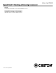
1
PN: IS1091LX REV. D
_____________________________________________________________________________________________________________________________________
OWNER’S MANUAL
INSTALLATION, OPERATION, & PARTS
SP1091 SERIES DYNA-SKIMTM AUTOMATIC SKIMMER
AND HYDROSTREAM RECIRCULATION SYSTEM
SP1091LX
SP1091WM
Your new Hayward Thru-Wall Skimmer makes pool maintenance easier and more
convenient. Leaves, insects and floating debris are pulled from the pool into the skimmer
basket. Clean the basket regularly to keep your pool sparkling clean and sanitary.
Basic safety precautions should always be followed, including the following: Failure to follow instructions can cause severe injury
and/or death.
This is the safety-alert symbol. When you see this symbol on your equipment or in this manual, look for one of the following
signal words and be alert to the potential for personal injury.
WARNING warns about hazards that could cause serious personal injury, death or major property damage and if
ignored presents a potential hazard.
CAUTION warns about hazards that will or can cause minor or moderate personal injury and/or property damage and
if ignored presents a potential hazard. It can also make consumers aware of actions that are unpredictable and unsafe.
The NOTICE label indicates special instructions that are important but not related to hazards.
MAXIMUM RECOMMENDED SYSTEM FLOW RATE BY PIPE SIZE
Pipe Size
[mm]
Flow rate
GPM [Liter/Min]
Pipe Size
[mm]
Flow rate
GPM [Liter/Min]
Pipe Size
[mm]
Flow rate
GPM [Liter/Min]
1”
[32]
20
[75]
1 ½”
[50]
45
[170]
2 ½”
[75]
110
[415]
1 ¼”
[40]
30
[110]
2”
[63]
80
[300]
3”
[90]
160
[600]
Page 2 of 4
DYNA-SKIM SKIMMERS
IS1091LX REV D
- WARNING - Read and follow all instructions in this owner’s manual and on
the equipment. Failure to follow instructions can cause severe injury and/or death.
IMPORTANT SAFETY INSTRUCTIONS
WARNING – Suction Entrapment Hazard.
Suction in suction outlets and/or suction outlet covers which are damaged, broken, cracked, missing,
or unsecured can cause severe injury or death due to the following entrapment hazards:
Hair Entrapment- Hair becomes knotted or snagged in an outlet cover.
Limb Entrapment- A limb sucked or inserted into an opening of a circulation outlet with a broken or missing cover in
the pool resulting in a mechanical bind or swelling
Body Suction Entrapment- Suction applied to a large portion of the body or limbs resulting in an entrapment.
Evisceration/ Disembowelment Entrapment- Suction applied directly to the intestines through an unprotected
sump or suction outlet with a missing or broken cover.
Mechanical Entrapment- Potential for jewelry, swimsuit, hair decorations, finger, toe or knuckle to be caught in an
opening of an outlet or cover.
o
o
o
o
o
o
To Reduce the risk of Entrapment Hazards:
o A minimum of two functioning suction outlets per pump must be installed. Suction outlets in the
same plane (i.e. floor or wall), must be installed a minimum of three feet (3’) [1 meter] apart, as
measured from suction center line to suction center line.
o Dual suction fittings shall be placed in such locations and distances to avoid “dual blockage” by a
user.
Dual suction fittings shall not be located on seating areas or on the backrest for such seating areas.
The maximum system flow rate shall not exceed the flow rating of any listed (per ASME/ANSI A112.19.8M-1987,
ASME A112.19.8-2007) suction outlet cover installed.
Never use a Pool or Spa if any suction outlet component is damaged, broken, cracked, missing, or not securely attached.
Replace damaged, broken, cracked, missing, or not securely attached suction outlet components immediately.
Two or more suction outlets per pump should be installed in accordance with latest APSP Standards and CPSC
guidelines, follow all National, State, and Local codes applicable.
Installation of a vacuum release system, which relieves entrapping suction, is recommended.
POOL PREPARATION
Fill the pool with approximately two (2) feet of water so the liner is under weight and stretched to the proper position
prior to installing the skimmer.
Note: The liner cannot be shifted after the skimmer and return holes have been cut.
1.
2.
1.
2.
3.
4.
SKIMMER ASSEMBY
If the SP1091E, Wide mouth extension, is not installed on the body, it must be assembled to the body prior to attempting to
install the skimmer in the pool.
To install the wide mouth extension, insert four (4) pan head screws 1” long through the lip of the extension and four (4)
through the throat of the skimmer. Place the gasket between the extension and the skimmer body. Firmly tighten the screws.
SKIMMER INSTALLATION
From the outside of the pool install the face-plate double gasket at skimmer cutout in the wall. Reach over the top rail of the
pool and carefully press the face-plate and liner against the gasket and skimmer cutout in the wall. Punch out the two top
corner holes using a blunt object. Insert two self-threading flat head screws (provided) into the top corner holes of the faceplate.
Carefully push the screws through the holes that have been pierced in the liner and through the double gasket. From the
outside of the pool, align the skimmer body with these screws. Lightly tighten the two screws.
Using a blunt object, pierce the remaining holes in the liner. Insert and lightly tighten the remaining flat head screws through
the face-plate, liner, gasket and into the corresponding holes on the skimmer. Firmly tighten all screws evenly, alternately
left and right, top and bottom.
Using the skimmer face plate as a guide, use a razor knife to trim only the liner, being careful not to the gasket, in the large
skimmer opening.
Page 3 of 4
1.
2.
3.
4.
5.
DYNA-SKIM SKIMMERS
IS1091LX REV D
RETURN FITTING INSTALLATION
The return fitting furnished with these skimmers is a SP1023. The hole required through the pool wall to install this fitting is
2.38±.03 inches. DO NOT CUT THE LINER.
Place one rubber gasket over the threads of the return fitting adapter and push the threaded end against the liner and through
the return cutout in the wall.
Applying outward pressure to the return fitting cut and “X” in the center of the exposed liner from outside the pool. The
return fitting will now be fully pressed against the liner and the wall on the inside of the pool. Using a razor knife, trim the
excess liner material from around the fitting threads on the outside of the pool.
Place the second rubber gasket and then the cork gasket over the threads of the return fitting now exposed outside of the pool.
Screw on the lock nut and tighten.
Screw on the adjustable directional ball fitting into the face of the return fitting from the outside of the pool. Position ball
fitting opening away from skimmer opening. Do not over-tighten.
Note: On-going leaks from the skimmer or wall fittings may cause pool wall
damage that eventually may result in pool wall failure.
RECOMMENDED WINTERIZING PROCEDURE
Drain pool level approximately six inches (6”) below skimmer opening. Remove
Hydrostream Eyeball fitting and securely plug wall fitting (1 ½” threaded plugs are
available from the dealer). Disconnect filter hoses from the skimmer and the wall
fitting. Be sure that the skimmer is kept free of water accumulation. Warranty does
not include damage caused by the formation of ice in the skimmer.
OPERATING INSTRUCTIONS
TO CLEAN SKIMMER BASKET
TO-VACUUM WITH SKIM-VAC
Remove top cover; or fold weir forward and squeeze tabs
1.
Remove weir from front of skimmer.
toward center to remove weir. Remove and clean basket.
2.
Attach vacuum hose to vac head and handle, and fill
Deluxe Skim-Vac Accessory
vacuum hose with water (place over pool inlet). Place
SKIM-VAC attaches to vac hose and is inserted in skimmer
SKIM-VAC over skimmer basket. Going through the
over basket, allowing you to conveniently vacuum through the
skimmer opening in the pool wall, attach the vacuum hose
skimmer basket.
to the SKIM-VAC hose adapter.
3.
Hold SKIM-VAC in place until any air hose is evacuated
by pump. Once air is removed, the pump suction will
hold the SKIM-VAC firmly in place.
Note: Take care not to damage or scuff the SKIM-VAC’s
specially designed sealing surface.
Page 4 of 4
DYNA-SKIM SKIMMERS
REF #
1
2
3
4
5
6
7
8
9
10
11
IS1091LX REV D
NO.
DESCRIPTION
REQUIRED
Skimmer Body (Not
-------procurable as a part)
1
SPX1091B
Cover
1
SP11041
Skim Vac
1
SPX1091C
Basket w/ Handle
1
SPX1091K1
Weir
1
Standard Butterfly
SPX1091G
Gasket
1
Widemouth
SPX1091E
Extension
1
Extension Screws
1 Set
(Procurable only with (Included in
-------SPX1090Z7A)
Item #11)
Widemouth Butterfly
SPX1091GW
Gasket
1
Widemouth Face
SPX1091F
Plate
1
Face Plate Screw
Pack (Includes
SPX1090Z7A screws for extension)
1 Set
PART #
SP1091WM
REF #
SP1091LX
PART #
1
--------
2
SPX1091B
3
SP11041
DESCRIPTION
NO.
REQUIRED
Skimmer Body (Not
procurable as a part)
1
Cover
1
Skim Vac
1
4
SPX1091C
Basket w/ Handle
1
5
SPX1091K1
Weir
1
6
SPX1091G
Standard Butterfly
Gasket
1
12
SPX1091D
Face Plate
1
13
SPX1090Z6A
Face Plate Screw
Pack
1 Set