1
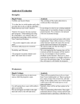
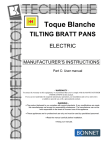
Crestline® Dampening System
Installation Instructions
A.B. Dick 350, 360, 375
Single & Dual Lever Machines
X88-20
01/01
Rev-A
GENERAL INFORMATION
ATTENTION
CRESTLINE®
DAMPENER
OWNER!
Accel Graphic Systems provides parts and service through its
authorized distributors and dealers. Therefore, all requests for
parts and service should be directed to your local dealer.
The philosophy of Accel Graphic Systems is to continually improve
all of its products. Written notices of changes and improvements
are sent to Accel Graphic Systems' Dealers.
If the operating characteristics or the appearance of your product
differs from those described in this manual, please contact your
local Accel Graphic Systems Dealer for updated information and
assistance.
Always update your dampener when improvements are made
available, especially those related to safety.
YOUR AUTHORIZED CRESTLINE® DEALER IS:
THE SERIAL NUMBER OF YOUR
CRESTLINE® DAMPENER(S) IS:
SAFETY
INFORMATION
2
FOR YOUR SAFETY, DO NOT DISENGAGE OR REMOVE ANY
GUARDS FROM THE CRESTLINE® DAMPENER. THE DAMPENER CONTAINS SOME INWARD ROTATING ROLLER NIPS
THAT CAN CAUSE INJURY IF LEFT UNGUARDED.
GENERAL INFORMATION
BASIC
CONFIGURATION
OF CRESTLINE®
b. 5/32" - 3/16" (4 - 5mm)
M
O
P
F
a. 5/32" (4mm)
Plate Cylinder
Adjustments
P
M
O
F
a. Form to Plate
b. Metering to Pan
TERMINOLOGY
TECHNICAL
ASSISTANCE
Roller Description
OPS
=
Operator's Side
NOPS
=
Non Operator's Side
=
=
=
=
Pan
Metering
Oscillator
Form
For technical assistance during the installation, please contact:
ACCEL GRAPHIC SYSTEMS
11103 Indian Trail
Dallas, TX 75229
PHONE (972) 484-6808
FAX (800) 365-6510
E-MAIL [email protected]
WEB SITE accelgraphicsystems.com
Crestline® is covered by U.S. Patents and Patents Pending
3
GENERAL INFORMATION
REQUIRED TOOLS
4
1.
Phillips Screwdriver
2.
Standard Screwdriver
3.
3/32" Allen Wrench
4.
1/8" Allen Wrench
5.
5/32" Allen Wrench
6.
7/16" Open End Wrench
7.
1/2" Open End Wrench
8.
3/8" Open End Wrench
9.
Spring Hook Tool
10.
3/32" Punch
11.
Hammer
GENERAL INFORMATION
PRE-INSTALLATION PROCEDURES AND
HOW TO PARALLEL THE DAMPENER.
1. Cut the ties holding the rollers and examine the rollers for
gouges,scratches or nicks.
2. Check the box and parts boards to make sure all pieces are
present and nothing has been damaged in shipment.
3. Check the dampener alignment by setting it on end on a flat
surface such as a cutter bed. If dampener rocks, it needs to be
realigned.Loosen the tie bar bolt and align the frames on the flat
surface. Retighten bolt.
5
6
DISASSEMBLY
1
2
Remove dampener and inker guards. Remove operating handles
from OPS. Remove side covers from OPS & NOPS. Remove top
2 oscillating rollers from the ink train.
If press is a single lever model remove dampener activating
mechanism by removing "E" ring and cap head screw (subject
arrows). Loosen the lock nut holding the cap head screw before
attempting to remove it.
NOTE: Do not remove this mechanism on multi lever A.B.
Dicks. It will be used to raise and lower the Crestline®
Dampener.
3
Remove vertical tension springs at OPS & NOPS (subject arrow).
7
8
DISASSEMBLY
4
Remove tie bar bolt (subject arrow) from dampener frame at OPS
& NOPS.
5
Remove water lock out bracket (subject arrow) at OPS & NOPS.
Brackets are short pieces of metal, each retained by 2 cap head
bolts.
6
The metering roller assembly can now be removed by holding the
tie bar (subject arrow) and pulling the mechanism out towards the
ink rollers.
9
10
DISASSEMBLY
7
8
9
Remove copper pan roller by loosening the 2 set screws on each
collar at the OPS & NOPS and moving them toward the center of
the press. There may be a small snap ring that holds the collar in
place, if so, remove the snap ring before attempting to remove
collar.
Remove bolt in the oscillator housing nearest the feed at OPS &
NOPS. Also remove the 2 screws that hold the lift shaft housing at
OPS (subject arrows).
Remove gear guard from the plate cylinder.
NOTE: Replace nut (subject arrow) immediately after
removing guard.
11
12
DISASSEMBLY
10
Remove large stud from OPS that held the water activating
mechanism. Remove the screw holding the dampener frame on
the OPS.
11
Unhook the spring attached to the water ductor arm (located near
subject arrow) at both OPS & NOPS.
12
Remove dampener frame from OPS. The shaft between the frames
is removed with the OPS frame as one piece.
13
14
DISASSEMBLY
13
Drive the TAPER PIN (make sure to hit the small end) out of the lift
shaft gear & remove the gear and shaft housing from the OPS
(subject arrow).
14
Remove the two nut and bolt combinations (subject arrow) at
NOPS. Remove any other nut and bolt combinations that may
secure the frame to the NOPS.
15
Remove the "E" rings on the lift shaft at the OPS & NOPS ("E" rings
near subject arrow), push arms in toward the center and remove the
shaft assembly.
15
16
DISASSEMBLY
16
17
18
Remove the NOPS dampener frame by loosening the collar on the
plate cylinder shaft (subject arrow). Gently tap the plate cylinder
toward operator side until there is enough clearance to pull out
frame. Once the frame is removed, pull cylinder back toward NOPS
and retighten set collar in its original position.
On single lever models, remove night latch link (subject arrow),
saving E-rings, washers, and spring for reinstallation.
Clean insides of press frames thoroughly with solvent and a rag.
OPTION: You can remove the tie bar that holds the water lockout
brackets. Remove the bracket assembly from the tie bar and return
the tie bar to its original position.
YOU ARE NOW READY TO INSTALL CRESTLINE®.
17
18
INSTALLATION
1
2
3
On newer model 360's & 375's, the installation of an adapter plate
(left hand picture) may be required at the OPS. The plate covers
a cut out in the press. Install the plate as shown. The bottom of the
hole in the plate aligns with the small depression in the cut out
(subject arrow) If the press frame does not have this cutout, discard
the adapter plate and proceed to the next step.
Install water form adjusting mechanism at OPS & NOPS by
inserting the spring stud through mechanism and then through the
vacant hole in the ink oscillator housing (the original bolt was
removed in disassembly step 8). On some very early models, this
hole is too small and must be drilled out to 1/4". Angle the
mechanism toward the delivery end of the press and finger tighten
nut.
THIS STEP FOR SINGLE LEVER MACHINES ONLY!
DUAL LEVER INSTRUCTIONS ON NEXT PAGE.
Install lift shaft by inserting the longer portion that extends past the
cams into the 5/8" hole in the OPS then dropping the shaft down
into the press and through the same hole at NOPS. DO NOT MOVE
CAMS TO INSTALL THE SHAFT. Slide on the bronze bearings
(subject arrow) at each end of the shaft with the flange to the
outside, and press into the frame. Light tapping around bearing
flange is usually sufficient to seat it. (On some early models, the
hole at the NOPS is only 1/2" and therefore a bearing is not used).
Once bearings are seated, slip set collar on each end of the shaft
but do not tighten at this time. PROCEED TO STEP 4
19
20
INSTALLATION
THIS STEP FOR DUAL LEVER MODELS ONLY!
Remove gear from end of lift shaft. Insert gear end of shaft through
the 5/8" hole in the OPS then dropping the shaft down into the press
and through the same hole at NOPS. DO NOT MOVE CAMS TO
INSTALL THE SHAFT. Slide on the bronze bearings (subject
arrow) at each end of the shaft with the flange to the outside, and
press into the frame. Light tapping around bearing flange is usually
sufficient to seat it. (On some early models, the hole at the NOPS
is only 1/2" and therefore a bearing is not used). Once bearings are
seated, slip set collar on each end of the shaft but do not tighten at
this time.
PROCEED TO STEP 4.
4
Sit the dampener down in between the side frames making sure
gears mesh.
5
Insert mounting studs through the dampener & into the vertical slot
in the press frame or hole in the adapter plate previously installed.
21
22
INSTALLATION
6
Position lift shaft side to side so the cams are spaced equally
between the bearings on the hanger brackets and lock the position
of the lift shaft with the set collars. The flat portion of the cam should
be facing up (subject arrow) in the neutral position.
7
Push down on dampener, making sure it seats at the bottom of the
slot or hole at both OPS & NOPS and fully tighten bolts. Slip washer
over cap head bolt.
8
Position water form adjusting mechanism at OPS & NOPS (subject
arrow) so they are parallel with the dampener frame as shown and
fully tighten nut on outside of press frame.
23
24
INSTALLATION
9
10
Install springs between dampener spring stud and the spring stud
in the water form adjusting mechanism (subject arrow).
THIS STEP FOR SINGLE LEVER MACHINES ONLY!
Replace the night latch link on the press with the new linkage
provided by Accel (lower subject arrow). Picture is shown with
single lever on the water off or night latch position. If the linkage is
installed pre-assembled (as shown in picture), you will slip the
control block (upper subject arrow) over the lift shaft as you connect
the linkage in the same manner as the original one. Use the new
sequence cam spring provided by Accel.
PROCEED TO STEP 11 - SINGLE LEVER MACHINES.
THIS STEP FOR DUAL LEVER MACHINES ONLY!
Slip provided stop bolt through slot in dampener activating lever
approximately 3/4" from the end (right hand subject arrow). Secure
with provided washer and nut. Move the activating lever all the way
to the right and against the top screw. Slip gear (left hand subject
arrow) over end of the lift shaft and engage teeth with activating
lever. Rotate lift shaft until the flats on the cams are facing up and
perfectly horizontal (parallel to floor). Tighten set screw in gear to
secure it to the lift shaft. NOTE: Picture shown with original shaft
housing in place. This was replaced in step 3 with a bronze bushing.
PROCEED TO STEP 11 FOR DUAL LEVER MACHINES.
25
26
INSTALLATION
11
THIS STEP FOR SINGLE-LEVER MACHINES ONLY!
Place the single lever in the "water on" position (2nd detent). Rotate
the lift shaft clockwise until the cams contact the ball bearing on the
dampener hanger brackets. Holding the shaft in this position,
tighten the set screws in the control block (subject arrow). Return
the single-lever shaft to the off position. The cams should rotate
clockwise and the ball bearings on the dampener hanger brackets
should rest over the "corner" of the cam.
NOTE: If you rotate the lift shaft too far it can affect the stripe
between the form roller and metering roller.
YOU ARE NOW READY TO MAKE FINAL ADJUSTMENTS.
CONTINUE TO NEXT PAGE.
THIS STEP FOR DUAL-LEVER MACHINES ONLY!
Slide the activating lever back all the way to the left while watching
the lift cams rotate clockwise under the ball bearings on the
dampener. When the corners of the cams pass just under the
bearings, you should be able to let go of the activating lever without
it springing back to the right. If this does not operate correctly, you
must reposition the stop bolt (from previous step) and reposition
gear on lift shaft. You may also have to increase the spring tension
on the activating lever by tightening nut on compressions spring
behind lever.
YOU ARE NOW READY TO MAKE FINAL ADJUSTMENTS.
CONTINUE TO NEXT PAGE.
27
28
FINAL ADJUSTMENTS
1
2
O
M
F
P
5/32"
Plate Cylinder
3
O
M
F
P
3/16"
Plate Cylinder
FORM ROLLER LIFT AND GEAR MESH
Place single lever in night latch (off for multi lever machines)
position and mount a plate to the press. Adjust set screws on the
dampener frame tie bar (subject arrow) until you have an equal
.050" - .060" of lift between form roller and plate cylinder. Turning
the screws down increases the gap between the form roller and
plate cylinder and vice-versa. There should also be a gap between
the metering roller and the form roller. After proper lift is obtained,
tighten lock nuts.
FORM ROLLER TO PLATE CYLINDER PRESSURE
Dab some ink on the oscillator and turn on the press. Move the
single lever to the Neutral ("On" for multi lever machines) position
to distribute the ink on the dampener. Place the dampener in the
"Night Latch" position and turn off the press.
Lower the dampener to the plate and back off again. This will leave
a stripe. The proper setting is an even 5/32" across the plate. Adjust
the stripe by turning the bolts (subject arrow) in the water form
adjusting mechanism. Turning the bolts down drops the dampener
and makes a wider stripe. Adjust it to 5/32" stripe to the plate and
tighten lock nuts against adjusting mechanism.
MAXIMUM METERING TO PAN ROLLER PRESSURE
Place the single lever dampener in the "Night Latch" position. Spin the
ratchet gears down until they stop against the cross bar. (They are not
yet locked to knobs). Turn the press on and let the press idle for 20
seconds. Check the stripe between the pan the metering rollers. It
should be 3/16". Adjust by turning the knurled knobs. Turning the
knobs down makes a wider stripe. Once the stripe is correct, lock the
ratchet gears to the knobs by tightening the set screws (2 each). This
position sets minimum water. Installation of Crestline® results in the
following changes in the single lever positions:
1. Night latch becomes the "Off" position.
2. Neutral becomes the "Water On" position.
3. Ink & Water position drops the ink forms to the plate.
29
30
GUARD INSTALLATION
1
2
3
Attach the guard mounting brackets to the press frames utilizing
the two existing holes (subject arrows left photo NOPS shown) in
each frame. The brackets attach to the outside of the press frames
using the provided 1/4-20 x 1/2 button head bolts and flanged lock
nuts. In the right photo (shown from NOPS side), note how the
angled side of the mounting bracket is towards the feeder side of
the press. On 375 model presses the two piece mounting bracket
goes on the NOPS.
Attach the tie bar to the lower hole (subject arrow) in the mounting
brackets using 1/4-20 x 3/8 button head bolts. Use the NOPS bolt
to also secure the hose clamp.
Install the pivot sleeve in the NOPS mounting bracket using the
large e-ring to secure it.
31
32
GUARD INSTALLATION
4
5
6
Set the inker and dampener guard on the press and align the holes
in the tabs on the top of the guards. From the NOPS slide the pivot
rod through the mounting bracket and guards into the OPS
mounting bracket. Secure the shaft with the small E-ring (subject
arrow) on the NOPS.
Locate the two holes, one each at the OPS and NOPS (lower
subject arrow). If you do not have this hole, drill a 9/32" diameter
hole 1 3/8" straight down from the hole above it (upper subject
arrow). See also "A.B. Dick 360/375 Side Frame Modification"
diagram on page 42.
Install the plate/blanket guard in the press and slide the hinge
blocks (subject arrow), located in the lower corners of the guards,
into the holes in the press frames from the previous step. Tighten
the bolts after centering the guard in the press.
33
34
GUARD INSTALLATION
7
If the inker and dampener guards are not square in the press they
can be adjusted by loosening the bolts securing the mounting
brackets to the press frames and twisting them as shown in the
diagram until they are square.
The installation of the guards is now complete. However, if your
press originally came equipped with safety switches, proceed with
the remaining steps to insure their continued operation.
If your press originally came with safety switches but some are
missing or not functioning properly, refer to the diagram on page 43
for the part numbers to order from your A.B. Dick dealer.
8
Remove the magnet from the original inker guard and install it on
the new one (subject arrow).
9
Install the provided plunger (subject arrow) on the NOPS of the
dampener guard and position it as necessary to reach the
microswitch on the press frame.
35
36
GUARD INSTALLATION
10
11
Install a magnet from one of the original plate guards on the
supplied “L” shaped bracket. Attach this bracket to the OPS side of
the new plate guard so that it switches with the old lower plate guard
switch.
Remove the female connectors from the ends of the wires that went
to the read switch that was removed to install the dampener. Strip
3/16" from the ends of the wire and crimp together using the
supplied butt connector.
37
BASIC OPERATION
START OF DAY
A. Make sure the oscillator and metering rollers are in place.
B. Spin knurled knobs until the shoulder on the ratchet stops
against the bar.
C. Mount plate to cylinder. Wipe down all plates before running.
Pre-ink the Crestline® dampener before running the plates with
an extremely light coverage of ink. Dab the ink on the oscillator only.
D. Place water bottle in bracket.
NOTE: Accel recommends using the proper fountain solution
for the plate material being run on the press. A good acid/gum
etch should be used with metal plates.
RUNNING
DURING THE DAY
A. In general, the Crestline® Dampener should not have to be
adjusted from job to job. The form roller setting should never be
changed unless it has deviated from the factory specification of
5/32" to the plate.
B. Adjustments to the amount of water fed to the plate are made
by the knurled knobs that apply pressure to the metering roller.
The dampener has been set up for minimum water. To increase
the water to the plate, turn the knurled knobs counterclockwise
1 or 2 clicks at a time. This opens the gap between the metering
and pan rollers and allows more water to the plate.
C. In general, more water will only be required when going from
a metal plate to an electrostatic or Silvermaster type plate.
38
CLEANING & MAINTENANCE
WASH UPS
DURING THE DAY
1. Remove bottle and drain the excess water from the pan.
2. Mount cleanup mat to the press or if applicable, a wash-up
attachment along with a metal plate to act as a bridge between
dampener and inker.
3. Turn on the press and squirt a small amount of press wash on
the ink and dampener rollers. (Squirt ink rollers only if using a
wash-up attachment.)
4. Drop both the dampener and ink forms to the plate. If using an
attachment, generally the dampener will pick up enough roller
wash off the plate to clean itself, so apply wash directly to the
dampener only when necessary.
5. Remove water pan and clean any solution left in it.
6. Be sure to wipe excess clean up solution from the ends
of the dampener metering and pan rollers.
END OF THE DAY
1. Wash up dampener. Pay close attention to cleaning the ends
of the pan and metering rollers that extend past the form
rollers.
2. Spin the knurled knobs up until the metering roller can be
removed.
3. Remove metering roller and wipe down thoroughly to remove
any excess wash that may be on the roller.
39
CLEANING&&MAINTENANCE
MAINTENANCE
CLEANING
DEGLAZING
THE DAMPENER
OILING AND
GREASING THE
DAMPENER
40
Periodic deglazing of water-soluble contaminants will be necessary with the Crestline®. Typically, once every 2-3 weeks will
be sufficient, unless you are running electrostatic plates on a
daily basis whereas deglazing should be performed weekly. A
50/50 solution of household ammonia and hot water can be
used for deglazing purposes. If you prefer a commercially
available deglazer, avoid those containing pumice or gritty
substances. Always follow deglazing with straight water and
then roller wash. Accel offers a product called COMPOUND X
that we recommend for deglazing our system. Contact your
dealer or Accel for more information.
A. Place a small amount of grease on the gears once a
month.
B. Inject grease into the oscillator grease fitting once a
month.
CLEANING AND MAINTENANCE
CRESTLINE®
CLEANING & MAINTENANCE CHART
Daily
Weekly
Bi-Weekly Monthly
Wash Rollers
Deglaze Rollers
Metal Plate Users
Silvermaster Plate Users
Electrostatic Plate Users
Grease Gears
Inspect Ball Bearings
Check Roller Pressures
Check Roller Surfaces
41
SIDE FRAME MODIFICATION
42
SAFETY SWITCH REPLACEMENT PARTS
43
A.B. DICK 350 / 360 (NOPS)
44
A.B. DICK 350 / 360 (OPS)
45
A.B. DICK 350 / 360
46
A.B. DICK 350 / 360
47
A.B. DICK 350 / 360
48
A.B. DICK 350 / 360
49
A.B. DICK 350 / 360
50
A.B. DICK 350 / 360
51
A.B. DICK 360 DUAL LEVER
52
A.B. DICK 350 / 360
53
A.B. DICK 375
54
A.B. DICK 375
55
A.B. DICK 375
56
A.B. DICK 375
57
A.B. DICK 375
58
A.B. DICK 375
59
A.B. DICK 375
60
A.B. DICK 375
61
A.B. DICK 375
62
11103 Indian Trail, Dallas, TX 75229 Phone 972-484-6808, Fax 800-365-6510
E-Mail [email protected], Web Site www.accel-us.com