1
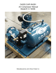
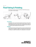
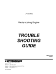
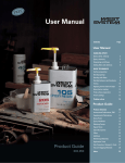
Owner’s Manual
Installation, Operation and Maintenance Instructions
for Models 2340, 2475, 2545, 7100, 15T & 3000
Two-Stage Reciprocating Air Compressors
IMPORTANT INFORMATION! READ AND FOLLOW THESE INSTRUCTIONS. RETAIN FOR REFERENCE.
SAFETY
GENERAL INFORMATION
DEFINITIONS ________________________________________
•DANGER WILL cause DEATH, SEVERE INJURY or substantial
property damage.
• WARNING
CAN cause DEATH, SEVERE INJURY or substantial
property damage.
• CAUTION
WILL or CAN cause MINOR INJURY or property
damage.
GENERAL SAFETY PRECAUTIONS ____________________
•DANGER INTAKE AIR. Can contain carbon monoxide or other
contaminants. Will cause serious injury or death.
Ingersoll-Rand air compressors are not designed,
intended or approved for breathing air. Compressed
air should not be used for breathing air applications
unless treated in accordance with all applicable
codes and regulations.
• WARNING
HAZARDOUS VOLTAGE. Can cause serious injury
or death. Disconnect power and bleed pressure
from the tank before servicing. Lockout/Tagout
machine. Compressor must be connected to
properly grounded circuit. See grounding
instructions in manual. Do not operate compressor
in wet conditions. Store indoors.
MOVING PARTS. Can cause serious injury. Do not
operate with guards removed. Machine may start
automatically. Disconnect power before servicing.
Lockout/Tagout machine.
HOT SURFACES. Can cause serious injury. Do not
touch. Allow to cool before servicing. Do not touch
hot compressor or tubing.
HIGH PRESSURE AIR. Bypassing, modifying or
removing safety/relief valves can cause serious
injury or death. Do not bypass, modify or remove
safety/relief valves. Do not direct air stream at body.
Rusted tanks can cause explosion and severe injury
or death. Drain tank daily or after each use. Drain
valve located at bottom of tank.
• CAUTION
INTRODUCTION _____________________________________
This manual provides safe and reliable instructions for the
installation, operation and maintenance of your Ingersoll-Rand air
compressor. Carefully read this manual before attempting to
operate or perform any maintenance. If you are uncertain about any
of the instructions or procedures provided in this manual, contact
Ingersoll-Rand. We recommend you retain this manual, and all
publications provided with your air compressor, in a location which
is accessible to all personnel who operate and service your
compressed air equipment.
APPLICATION _______________________________________
Ingersoll-Rand’s standard two-stage lubricated air compressors are
single-acting, air-cooled machines. Typical compressors are
furnished as compact, self-contained, air receiver tank mounted
units that are automatically regulated and driven by an electric
motor or gasoline engine. An air-cooled aftercooler, low oil level
shutdown switch and automatic drain valve are among the optional
accessories that can be furnished. Bare compressor pumps and
baseplate-mounted units are also available.
These compressors may be used for a variety of compressed air
application up to 250 PSIG (17.5 kg/cm²). Application of these
compressors as either a primary or supplementary source of air is
virtually unlimited in industrial plants, service stations and auto
repair shops. Supplementary service includes such uses as
furnishing air at pressure not carried in regular shop lines, air at
isolated locations, and standby service for air when larger
compressors are shut down.
TWO-STAGE OPERATION _____________________________
Two-stage compressors consist of one or two first-stage cylinders
with the same bore size and one second-stage cylinder with a
smaller bore size.
Typical Two-Stage, Two
Cylinder Unit
Typical Two-Stage, Three
Cylinder Unit
RISK OF BURSTING. Use only suitable air handling
parts acceptable for pressure of not less than the
maximum allowable working pressure of the
machine.
C.C.N. : 22607402
Rev.
:A
Date
: February 2005
© Ingersoll-Rand Company
Printed in U.S.A.
http://air.irco.com
2
The basic principle of operation is as follows: On the suction stroke
of the first-stage piston(s), air at atmospheric pressure enters the
cylinders through the inlet filter(s) and then the inlet valves located
in the head. On the compression stroke of the first-stage piston(s),
the air is compressed to an intermediate pressure and discharged
through the discharge valves(s) into common manifold(s). From the
manifold(s) the air passes through the intercooler tubes, where the
heat of first-stage compression is removed. On the suction stroke of
the second-stage piston this cooled air enters the second-stage
cylinder through the inlet valve. The compression stroke of the
second-stage piston compresses the air to the final discharge
pressure and forces it out through the discharge valve into the
receiver tank or system. If cooling of the discharge air is required,
an air-cooled aftercooler should be installed between the
compressor discharge and the receiver tank or system.
For maintaining the receiver tank or system air pressure within
predetermined limits, the compressor may be operated with
automatic start & stop control or constant speed control regulation.
The type of regulation used depends upon the application.
INSTALLATION
SELECTING A LOCATION _____________________________
ELECTRIC MOTOR UNITS. For most electric motor units, select a
relatively clean and dry well-lighted indoor area with plenty of space
for proper ventilation, cooling air flow and accessibility. Provide
1,000 cubic feet of fresh air per 5 horsepower. Locate the unit at
least 15 inches (38 cm) from walls, and make sure the main power
supply is clearly identified and accessible.
Unless the electrical components of the unit are specially protected
for outdoor use, do not install an electric motor unit outdoors or in
an area that will expose the electrical components to rain, snow or
sources of appreciable moisture.
WARNING FOR UNITS EQUIPPED
WITH ELECTRIC DRAIN VALVE
• WARNING
ADDITIONAL REFERENCES ___________________________
Unless otherwise stated, dimensions, weights and measurements
are provided in standard U.S. measure followed in parentheses by
the metric conversion. Any torque values given are stated in inch or
foot pounds followed by the Newton-meter equivalent in
parentheses. Electrical characteristics are given in
voltage-phase-hertz.
RECEIPT & INSPECTION
Ensure adequate lifting equipment is available for unloading and
moving the unit to the installation site.
NOTE
Lifting equipment must be properly rated for the
weight of the unit.
• CAUTION
Lift the unit by the shipping skid only. Do not use
the motor lifting eye to lift the entire unit. The motor
lifting eye is for removing the motor from the unit
only.
• CAUTION! Do not work on or walk under the unit while it is
suspended.
Before signing the delivery receipt, inspect for damage and missing
parts. If damage or missing parts are apparent, make the
appropriate notation on the delivery receipt, then sign the receipt.
Immediately contact the carrier for an inspection.
All material must be held in the receiving location for the carrier’s
inspection.
Delivery receipts that have been signed without a notation of
damage or missing parts are considered to be delivered “clear.”
Subsequent claims are then considered to be concealed damage
claims. Settle damage claims directly with the transportation
company.
If you discover damage after receiving the unit (concealed damage),
the carrier must be notified within 15 days of receipt and an
inspection must be requested by telephone with confirmation in
writing. On concealed damage claims, the burden of establishing
that the unit was damaged in transit reverts back to the claimant.
The electric drain valve incorporates arcing or
sparking parts, such as snap switches, receptacles
and the like that tend to produce arcs or sparks
and, therefore, when located in a garage, the
compressor should be in a room or enclosure
provided for the purpose, or the electric drain
valve should be 18 inches (457 mm) or more above
the floor.
GASOLINE ENGINE UNITS. For gasoline engine units, keep the
engine at least 3 feet (1 m) away from building walls and other
equipment. Install the unit in a location with plenty of space for
proper ventilation, cooling air flow and accessibility. Do not install or
operate a gasoline engine unit in a confined area.
AMBIENT TEMPERATURE CONSIDERATIONS. Ideal operating
temperatures are between 32°F and 100°F (0°C and 37.8°C). If
temperatures consistently drop below 32°F (0°C), install the
compressor in a heated area. If this is not possible, you must
protect safety/relief valves and drain valves from freezing. If
temperatures are consistently below 40°F (4.4°C), consider
installing an external crankcase heater kit, especially if the
compressor has difficulty starting.
• CAUTION
Never operate the compressor in temperatures
below -15°F (-26.1°C) or above 125°F (51.0°C).
HUMID AREAS. In frequently humid areas, moisture may form in
the pump and produce sludge in the lubricant, causing running parts
to wear out prematurely. Excessive moisture is especially likely to
occur if the unit is located in an unheated area that is subject to
large temperature changes.
Two signs of excessive humidity are external condensation on the
pump when it cools down and a “milky” appearance in petroleum
lubricant.
You may be able to prevent moisture from forming in the pump by
increasing ventilation, operating for longer intervals or installing an
external crankcase heater kit.
NOISE CONSIDERATIONS. Consult local officials for information
regarding acceptable noise levels in your area. To reduce excessive
noise, use vibration isolator pads or intake silencers, relocate the
unit or construct total enclosures or baffle walls.
Read the unit nameplate to verify it is the model ordered, and read
the motor nameplate to verify it is compatible with your electrical
conditions. Make sure electrical enclosures and components are
appropriate for the installation environment.
http://air.irco.com
3
MOUNTING _________________________________________
• WARNING
Typical Remote Air Inlet Piping.
Remove the unit from the skid before mounting.
ELECTRIC MOTOR UNITS. Bolt the unit to a firm, level foundation
(such as a concrete floor). Do not bolt uneven feet tightly to the
foundation, as this will cause excessive stress on the receiver tank.
Use metal shims under the “short” feet if necessary.
HOOD
ELBOW
Typical Permanent Mounting (Customer Supplied Hardware)
Direct to compressor
air intake (if distance
is less than 6 feet)
SUPPORT
AIR INLET
FILTER
PIPE
OUTSIDE
WALL
SUPPORT
INTAKE HOSE
TEE
HOSE
FITTING
BUSHINGS
GASOLINE ENGINE UNITS. Bolt the unit to a firm, level
foundation. Do not bolt uneven feet tightly to the foundation, as this
will cause excessive stress on the receiver tank. Use metal shims
under the “short” feet if necessary. Gasoline engine units mounted
on truck beds must be fastened securely without applying excessive
stress on the receiver tank. We recommend installing a vibration
isolator kit with gasoline engine models.
INSTALLING REMOTE AIR INLET PIPING _______________
• CAUTION
Do not operate the unit without air inlet filtration.
If the air around the unit is relatively free of dirt, install the air inlet
filter at the inlet connection at the pump. If the air is dirty, pipe the
filter to a source of clean air. Use PVC plastic tubes for remote inlet
piping. Do not use black pipe or galvanized pipe, as these promote
sweating and rust. Consider installing an in-line type filter for ease
of cleaning and replacement. Make the line as short and direct as
possible and as large, or larger, than the diameter of the inlet
connection on the pump. Do not install piping with a diameter lower
than that of the pump intake.
Increase the pipe diameter one size for every 10 feet (3 m) of length
or every 90° bend. Make sure the piping is adequately braced.
If you pipe the filter outdoors, cover it with a hood to prevent the
entrance of rain or snow.
Heavy duty filter elements and filtration equipment are available for
fine airborne dust, such as cement and rock dust.
DRAIN VALVE
INSTALLING DISCHARGE PIPING ______________________
• WARNING
Do not use plastic pipe, soldered copper fittings,
rubber hose, or lead-tin soldered joints anywhere in
the compressed air system.
• CAUTION! If you will be using synthetic compressor lubricant,
all downstream piping material and system
components must be compatible. Refer to the
following material compatibility list. If there are
incompatible materials present in your system, or if
there are materials not included in the list, contact
Ingersoll-Rand for recommendations.
SYNTHETIC COMPRESSOR LUBRICANT
MATERIAL COMPATIBILITY LIST
SUITABLE
Viton®, Teflon®, Epoxy (Glass Filled), Oil Resistant Alkyd, Fluorosilicone,
Fluorocarbon, Polysulfide, 2-Component Urethane, Nylon, Delrin®,
Celcon®, High Nitrile Rubber (Buna N. NBR more than 36% Acrylonitrile),
Polyurethane, Polyethylene, Epichlorohydrin, Polyacrylate, Melamine,
Polypropylene, Baked Phenolics, Epoxy, Modified Alkyds
(® indicates trademark of DuPont Corporation)
NOT RECOMMENDED
Neoprene, Natural Rubber, SBR Rubber, Acrylic Paint, Lacquer, Varnish,
Polystyrene, PVC, ABS, Polycarbonate, Cellulose Acetate, Low Nitrile
Rubber (Buna N. NBR less than 36% Acrylonitrile), EPDM, Ethylene Vinyl
Acetate, Latex, EPR, Acrylics, Phenoxy, Polysulfones, Styrene Acrylonitrile
(San), Butyl
NOTE
All compressed air systems generate condensate
which accumulates in any drain point (e.g. tanks,
filters, drip legs, aftercoolers, dryers). This
condensate contains lubricating oil and/or
substances which may be regulated and must be
disposed of in accordance with local, state, and
federal laws and regulations.
GENERAL REQUIREMENTS. The piping, fittings, air receiver tank,
etc. must be certified safe for at least the maximum working
pressure of the unit. Use hard-welded or threaded steel or copper
pipes and cast iron fittings that are certified safe for the unit’s
discharge pressure and temperature. DO NOT USE PVC PLASTIC
IN THE COMPRESSED AIR DISCHARGE LINE. Use pipe thread
sealant on all threads, and make up joints tightly to prevent air
leaks.
http://air.irco.com
4
CONDENSATE DISCHARGE PIPING. If installing a condensate
discharge line, the piping must be at least one size larger than the
connection, as short and direct as possible, secured tightly and
routed to a suitable drain point or waste container. Condensate
must be disposed of in accordance with local, state, and federal
laws and regulations.
• WARNING
If an aftercooler, check valve, block valve, or any
other restriction is added to the compressor
discharge, install a properly-sized ASME approved
safety/relief valve between the compressor
discharge and the restriction.
INSTALLING ELECTRICAL WIRING (ELECTRIC MOTOR
UNITS) _____________________________________________
• WARNING
Electrical installation and service should be
performed by a qualified electrician who is familiar
with all applicable local, state and federal laws and
regulations.
GENERAL. The motor rating, as shown on the motor nameplate,
and the power supply must have compatible voltage, phase and
hertz characteristics.
WIRE SIZE. The electrical wiring between the power supply and
electric motor varies according to motor horsepower and other
factors. Install adequately sized power leads to protect against
excessive voltage drop during start-up. Refer to the National
Electric Code (NEC) for information on selecting the proper wire
size and securing electrical connections. If you connect additional
electrical equipment to the same circuit, consider the total electrical
load when selecting the proper wire size. DO NOT USE
UNDERSIZE WIRE.
PRESSURE SWITCH. On units without a factory-installed pressure
switch, wire a pressure switch in accordance with the appropriate
wiring schematic in the DIAGRAMS section of this manual. Mount
the pressure switch in accordance with the manufacturer’s
recommendations. The connecting line to the receiver tank must be
as short and direct as possible, and certified safe for at least the
maximum working pressure of the unit.
CONNECTING A BATTERY (GASOLINE ENGINE UNITS) __
NOTE
If you will be making connections to a remote
battery, the engine on the compressor unit must be
equipped with an alternator.
BATTERY. A 12 volt battery with a minimum current rating of 250
CCA (cold cranking amps) and minimum ampere-hour rating of 24
Ah should be sufficient for cranking most electric start engines.
BATTERY CABLES. Refer to the following table for size and length
recommendations.
Cable
Maximum
Size (GA)
Length
6
4
2
5’ (1.5 m.)
7’-2.5" (2.1 m.)
12’ (3.6 m.)
CONNECTION PROCEDURES:
1. Connect the battery positive (+) cable (A) to the starter solenoid
terminal (B).
If wire size information is not available, the wire sizes shown in the
following wire selection chart can be used as a safe guide, if the
distance does not exceed 50 feet (15.3 m). For longer distances,
consult and electrical contractor or the local electric company for
recommendations.
MOTOR
SINGLE
THREE
HP
PHASE
PHASE
115V
230V
200V
230V
460V
575V
1
12
14
14
14
14
14
1.5
10
14
14
14
14
14
2
8
14
14
14
14
14
3
8
12
14
14
14
14
5
4
8
10
12
14
14
6
8
10
14
14
10
8
8
12
14
15
4
6
10
10
20
3
4
8
10
25
1
2
6
8
30
0
1
6
8
7.5
MAGNETIC STARTER. If the motor installed on your unit has a
motor reset button, it does not require a magnetic starter. If the
motor does not have this button and the unit does not have a
factory-installed starter, install a magnetic starter with thermal
overload protection. Follow the manufacturer’s instructions for
installation. Ingersoll-Rand cannot accept responsibility for
damages arising from failure to provide adequate motor protection.
FUSES. Refer to the NEC to determine the proper fuse or circuit
breaker rating required. When selecting fuses, remember the
momentary starting current of an electric motor is greater than its
full load current. Time-delay or “slow-blow” fuses are recommended.
2. Connect the battery negative (-) cable (C) to the bolt shown in the
following illustration. Secure the wire in place by screwing a
suitably-sized nut onto the bolt and down onto the terminal.
Kohler
Honda
Kawasaki
Ingersoll-Rand
3. Connect the battery positive (+) cable (A) to the battery positive (+)
terminal.
4. Connect the battery negative (-) cable to the battery negative (-)
terminal.
5. Coat the terminals and cable ends with corrosion-preventive grease.
http://air.irco.com
5
• WARNING
Remove the cable from the negative (-) side of the
battery before servicing.
Refer to the following table for crankcase capacity.
Model
Refer to the engine manufacturer’s instructions for more
information.
FUEL PUMP INSTALLATION (GASOLINE ENGINE UNITS) _
Some engines use an optional fuel pump to supply gasoline to the
engine directly from a vehicle’s onboard fuel system. Install the fuel
pump within 12 inches (30 cm) of the bottom surface of the vehicle’s
fuel tank. Protect the pump from contamination by installing a fuel
isolation valve and an inline filter between the pump fuel system.
Crankcase Capacity
2340
28 oz. (827 ml.)
2475
41 oz. (1212 ml.)
2545
73 oz. (2158 ml.)
7100
80 oz. (2365 ml.)
15T, 3000
144 oz. (4258 ml.)
Use one of the following methods illustrated to determine when the
crankcase is full.
COMPRESSOR LUBRICATION _________________________
• CAUTION
Do not operate without lubricant or with inadequate
lubricant. Ingersoll-Rand is not responsible for
compressor failure caused by inadequate
lubrication.
SYNTHETIC COMPRESSOR LUBRICANT. Ingersoll-Rand
recommends All Season Select synthetic lubricant from start-up.
See the WARRANTY section for extended warranty information.
ALTERNATE LUBRICANTS. You may use XL-300 or a comparable
petroleum-based lubricant that is premium quality, does not contain
detergents, contains only anti-rust, anti-oxidation, and anti-foam
agents as additives, has a flashpoint of 440°F (227°C) or higher,
and has an auto-ignition point of 650°F (343°C) or higher.
A = FULL level at bottom thread of oil fill opening on units without
sight glass or dipstick.
See the petroleum lubricant viscosity table below. The table is
intended as a general guide only. Heavy duty operating conditions
require heavier viscosities. Refer specific operating conditions to
Ingersoll-Rand for recommendations.
C = FULL level on units with sight glass.
Temperature Around
Compressor
°F
°C
Viscosity @ 100°F
(37.8°C)
SUS
Centistokes
Viscosity Grade
B = ADD level below bottom thread of oil fill opening on units
without sight glass or dipstick.
D = ADD level on units with sight glass.
E = ADD level on units with dipstick.
F = FULL level on units with dipstick.
ISO
SAE
< 40
< 4.4
150
32
32
10
40-80
4.4-26.7
500
110
100
30
LOW OIL LEVEL SWITCH _____________________________
80-125
26.7-51.0
750
165
150
40
A float activated low oil level switch may be installed to protect your
unit against damage due to insufficient compressor oil level. Low oil
level in the compressor crankcase causes the switch contacts to
open, thus shutting the unit down until the proper oil level has been
restored.
If you use a petroleum-based compressor lubricant at start-up and
decide to convert to All Season Select later on, the pump must be
decarbonized and flushed before conversion. Contact
Ingersoll-Rand for more information.
FILLING PROCEDURES:
1. Unscrew and remove the oil fill plug.
2. Fill the crankcase with lubricant.
3. Replace the oil fill plug HAND TIGHT ONLY.
• CAUTION Do not remove the oil fill plug while the compressor
is running.
Proper protection against low oil level depends on proper
adjustment of the low oil level switch. During the initial run, stop the
unit and drain one quart of oil from the compressor crankcase into a
suitable clean container. Listen for the switch to click or check the
switch with a continuity tester.
The float sometimes gets cocked or stuck during shipping. If the
float is cocked or stuck, open the disconnect switch, drain the
remaining oil, remove the crankcase cover and then free the float.
Reassemble and then reuse the same oil.
NOTE
http://air.irco.com
If the float is cocked in the low position, the unit
cannot start.
6
START-UP (GASOLINE ENGINE UNITS) _________________
OPERATION
• WARNING
INTERMITTENT DUTY FORMULA ______________________
Units operating above 200 PSIG are to be operated according to the
"Intermittent Duty Formula."
INTERMITTENT DUTY FORMULA
Pump-up time should not ordinarily exceed thirty (30)
minutes or be less than ten (10) minutes. Shutdown
periods between cycles of operation should be at least
equal to the pump-up time. Note: When the compressor
is regulated by constant speed control, the shutdown
period is the time the compressor is operating
unloaded.
Do not operate gasoline engine units in an enclosed
area.
1. Release any remaining tank pressure by slowly opening the manual
drain valve.
2. Turn on the engine gasoline supply.
3. Put the choke in the “on” position.
4. Close the service valve and put the unloader lever in the “unload”
(A) position for Kawasaki and Honda engine driven models, or the
“load” (B) position for Kohler engine driven models.
5. Start the engine, release the choke, and allow the engine to warm
up for two to three minutes.
6. Return the unloader lever to the “load” (B) position on Kawasaki and
Honda engine driven models.
Typical Unloader (A = Unload, B = Load)
A
A pump-up time limit with the following cool-down period is
recommended to protect the valves and heads against stabilized
high operating temperatures, which could rapidly build up carbon in
these areas.
B
All inquiries for high-pressure compressor application where the
"use" cycle differs from the "Intermittent Duty Formula" should be
referred to Ingersoll-Rand.
START-UP (ELECTRIC MOTOR DRIVEN MODELS) _______
1. Close the service valve.
2. Release any remaining tank pressure by slowly opening the manual
drain valve.
3. Close the manual drain valve and apply power to the compressor. If
the pressure switch is equipped with an “ON/AUTO-OFF” lever, flip
the switch to the “ON/AUTO” position. If the unit is equipped with a
control panel “ON/OFF” switch, move the switch to the “ON”
position.
Typical Pressure Switch Lever (If Equipped)
NOTE
Turn the gasoline supply off when the compressor
is not being used.
NOTE
Some gasoline engine driven compressors require
5-8 break-in hours of operation before reaching full
capacity and speed.
COMPRESSOR CONTROLS ___________________________
AUTOMATIC START & STOP CONTROL. This type of control
applies to electric motor driven models under 10 horsepower.
NOTE
Automatic Start & Stop Control is intended for use
when the motor will start no more than 6 times per
hour.
When the receiver tank pressure reaches the factory pre-set
maximum pressure (usually 175 PSIG), the pressure switch stops
the unit. When the receiver tank pressure drops below the factory
pre-set minimum (usually 135 PSIG), the pressure switch resets
and restarts the unit.
CONSTANT SPEED CONTROL. This type of control applies to
gasoline engine units.
4. Slowly open the service valve.
Typical Service Valve (A = Open, B = Closed)
When the receiver tank pressure reaches the factory pre-set
maximum pressure (usually 175 PSIG), the unloader slows down
the engine and the unit stops pumping. When the receiver tank
pressure drops to the factory pre-set minimum (usually 145 PSIG),
the unloader resets, the engine returns to full speed, and the unit
resumes pumping.
• CAUTION
Unusual noise or vibration indicates a problem. Do
not continue to operate until you identify and
correct the source of the problem.
NOTE
Ensure the direction of rotation is correct per the
arrow on the motor. If the rotation is incorrect on
three-phase units, interchange any two of the three
leads.
DUAL CONTROL. This type of control applies to electric motor
units over 10 horsepower. Select either automatic start and stop
control or constant speed control by adjusting the knob on the
auxiliary valve. For automatic start and stop control, turn the knob
on the auxiliary valve fully clockwise to disable the auxiliary valve.
The pressure switch will then start and stop the unit.
NOTE
http://air.irco.com
For dual control models, automatic start and stop is
preferred.
7
Pressure Switch Range Adjustment.
Auxiliary Valve.
Select constant speed control if the unit restarts in less than 10
minute intervals or runs more than 40 minutes per hour. Turn the
knob fully counterclockwise to run the unit continually. When the
receiver tank pressure reaches 170 PSIG, the unit runs but does not
pump.
NOTE
The auxiliary valve is factory pre-set at 5 PSIG lower
than the factory pressure switch setting.
• CAUTION
Running unloaded for more than 20 minutes per
hour or more than 15 minutes continually with the
use of constant speed control will cause oil
pumping and should be avoided.
PRESSURE SWITCH ADJUSTMENT ____________________
• WARNING
High voltage is present at the pressure switch
contacts when the power supply is connected.
Disconnect, lock and tag main power supply before
making adjustments.
• CAUTION
Do not adjust the pressure switch to exceed the
maximum discharge pressure of the unit.
NOTE
Adjust the pressure switch only if adjustments are
absolutely necessary.
CUT-IN & CUT-OUT. The cut-out (compressor shut-down) is the
pressure at which the switch contacts open, and the cut-in
(compressor restart) is the pressure at which the switch contacts
close. See COMPRESSOR CONTROLS.
ADJUSTMENT CONTROLS. All pressure switches have a range
adjustment control (A). Some pressure switches also have a
differential adjustment (B) control. On switches without a differential
adjustment control, the span between cut-in and cut-out pressure
levels switches is factory set for 40 ± 4 PSIG and cannot be
adjusted.
NOTE
Some pressure switches are equipped with an
on-off lever used to open and close the electrical
contacts inside the switch. THIS LEVER IS NOT A
DIFFERENTIAL ADJUSTMENT CONTROL. The
pressure switches with the on-off lever do not have
a differential adjustment control.
ADJUSTMENT PROCEDURES (SWITCHES WITH DIFFERENTIAL
ADJUSTMENT CONTROL):
1. Remove the pressure switch cover.
2. Set the cut-in pressure with the range adjustment nut. Turn the nut
clockwise (in) to increase the pressure or counter-clockwise (out) to
decrease the pressure.
NOTE:
One full turn changes the setting approximately 2
PSIG.
3. Set the cut-out pressure with the differential adjustment. Turn the
differential adjustment nut clockwise (in) to increase the pressure or
counter-clockwise (out) to decrease the pressure.
NOTE:
One full turn changes the setting approximately 2
PSIG.
4. Replace the cover, reconnect the power supply and start the unit.
5. Note the pressure gauge reading at which the unit cuts out.
6. Repeat the adjustment procedure if necessary.
The minimum possible differential is approximately 20% of cutout
pressure. It is advisable to have as wide a differential as possible to
avoid frequent starting and stopping of the unit. Note the pressure
gauge reading at which the unit cuts-out and re-establish this point
if necessary.
Note the interaction between the range and differential adjustments,
i.e., if the cut-out is increased, the differential will also increase, or
if the differential is narrowed, the cut-out will be reduced, etc. These
factors must be considered when adjusting the switch and
compensated for accordingly.
STARTING UNLOADING SYSTEM ______________________
The starting unloading feature exists on certain models. The
purpose of the system is to relieve cylinder pressure when the unit
stops, permitting it to start against a light load. A light load
increases the life of the driver and belts and also reduces the
possibility of tripping the overload relay. The system operates in the
following manner:
ADJUSTMENT PROCEDURES (SWITCHES WITHOUT
DIFFERENTIAL ADJUSTMENT CONTROL):
The centrifugal unloader is attached to the end of the crankshaft as
shown in the following illustrations.
1. Remove the pressure switch cover.
2. Adjust the range by turning the range adjustment screw clockwise
(in) to increase the cut-out point or counter-clockwise (out) to
decrease the cut-out point.
NOTE:
One full turn changes the setting approximately 2
PSIG.
When the unit starts, centrifugal force acts upon the unloader
weights and they swing outward. This permits the plunger and thrust
pin to move inward and the pilot valve to close. The escape path to
atmosphere for the cylinder pressure is now closed and the
compressor pumps air in a normal manner.
3. Replace cover, reconnect power supply and start the compressor.
4. Note the pressure gauge reading at which the compressor cuts out.
5. Repeat adjustment procedure if necessary.
When the unit stops, the weights retract, permitting the thrust pin
spring to move the plunger and thrust pin outward. The thrust pin
opens the pilot valve and the trapped air pressure escapes from the
cylinder and intercooler through a passage in the frame end cover,
through the unloader tube and to atmosphere through the inlet
filter/silencer.
http://air.irco.com
8
BREATHER/UNLOADER BY-PASS _____________________
Position of weight and thrust pin when unit is operating.
The breather/unloader by-pass tube lines eliminates air pressure
build-up in the compressor frame by providing a passage for the air
to escape through the inlet unloader (if opened) or (if closed)
through the check valve, therefore, by-passing the inlet unloader
and escaping to atmosphere through the inlet filter/silencer.
OIL CONSUMPTION CHECK ___________________________
A rule of thumb in determining a "passing grade" for oil consumption
is to consider consumption at or above 50 horsepower-hours per
ounce to be acceptable.
The formula is as follows:
Horsepower
X
Hours of Operation
=
Ounces of Oil Used
Horsepower Hours
per Ounce
Position of weight and thrust pin when unit is stopped.
To apply this formula, consider the size of the machine. In the
following example, a 5 horsepower compressor uses 2 ounces of oil
every 20 hours of operation.
5 Horsepower
X
20 Hours of
Operation
=
50 Horsepower
Hours per Ounce
2 Ounces of Oil Used
The compressor in the example passes the oil consumption test.
NOTE
New or rebuilt compressor pumps will discharge
higher than normal amounts of oil until the piston
rings are seated (approximately 100 operating
hours).
MAINTENANCE
PILOT VALVE ADJUSTMENT __________________________
• WARNING
Before performing maintenance, release air
pressure from the system and disconnect, lock and
tag the main power supply or disconnect the wire
from the engine spark plug.
NOTE
All compressed air systems contain maintenance
parts (e.g. lubricating oil, filters, separators) which
are periodically replaced. These used parts may be,
or may contain, substances that are regulated and
must be disposed of in accordance with local, state,
and federal laws and regulations.
NOTE
Take note of the positions and locations of parts
during disassembly to make reassembly easier. The
assembly sequences and parts illustrated may differ
for your particular unit.
NOTE
Any service operations not explained in this manual
should be performed by an authorized service
representative.
NOTE
Reference the engine owner's manual for engine
care information.
NOTE
The following maintenance schedule has been
developed for typical applications. Maintenance
intervals should be shortened in harsher
environments.
If the pilot valve tube line is excessively hot, it is a good indication
that the pilot valve is leaking and adjustment is required.
To adjust the pilot valve, proceed as follows:
1. Stop the unit and disconnect and tag the electrical supply main
switch to prevent accidental start-up.
2. Remove the pilot valve tube and the tube fittings.
3. Remove the pilot valve body and all existing shims.
4. Screw the pilot valve body back into the frame end cover (without
any shims) until contact with the thrust pin is felt. Advance the pilot
valve body 1/4 to 1/2 turn more.
If contact with the thrust pin cannot be felt, the following steps may
be necessary to locate the contact point:
1. Insert a small instrument (punch, rod, nail, etc.) into the end of the
pilot valve until it contacts the valve stem.
2. While still inserted in the pilot valve, make a mark on the instrument
even with the outside edge of the pilot valve body.
3. Keeping the instrument pressed lightly against the valve stem, screw
the pilot valve body into the frame end cover. When the mark on the
instrument starts moving out away from the edge of the pilot valve
body, contact has been made with the thrust pin.
4. Advance the pilot valve body 1/4 to 1/2 turn more and proceed with
step five.
5. Measure the gap between the pilot valve body and the frame end
cover.
6. Remove the pilot valve body and add enough shims to fill the gap
measured in step five.
7. Screw the pilot valve body back into the frame end cover until the
body is tight on the shims.
8. Reconnect the pilot valve tube and tube fittings.
http://air.irco.com
9
BELT ADJUSTMENT _________________________________
MAINTENANCE SCHEDULE
Daily or Before
Each
Operation
l Check for oil leaks.
l Check lubricant level. Fill as needed.
l Drain receiver tank condensate (if automatic
l
l
l
l
Weekly
l
l
Monthly
l
l
3/500 *
l
l
l
12/2000 *
l
l
l
l
draining device is not provided). Open manual
drain valve and collect and dispose of
condensate accordingly.
Check for unusual noise and vibration.
Ensure beltguards and covers are securely in
place.
Ensure engine (if supplied) is filled with fuel
and lubricant according to the manufacturer’s
recommendations.
Ensure area around compressor is free from
rags, tools, debris, and flammable or
explosive materials.
Observe operation of safety/relief valves while
the compressor is running. Replace
safety/relief valves that do not operate freely.
Inspect air filter element(s). Clean if
necessary.
Inspect for air leaks. Squirt soapy water
around joints during compressor operation
and watch for bubbles.
Check tightness of screws and bolts. Tighten
as needed.
Inspect drive belts. Adjust if necessary.
Clean exterior.
Change petroleum lubricant while crankcase
is warm.
Drain compressor oil and clean oil sight glass
Install maintenance pak
— or —
Change synthetic lubricant while crankcase is
warm.
Replace filter element.
CHECKING BELT TENSION. Check belt tension should be
occasionally, especially if looseness is suspected. New belts must
also be properly tensioned upon installation.
TENSIONING BELTS. Belt tensioning can be achieved by
loosening the motor or engine anchor screws, pushing the motor or
engine away from the pump, and retightening the motor or engine
anchor screws. Some units are equipped with a belt tensioning bolt
that, when turned, pulls the motor or engine away from the pump.
Otherwise, the motor can be easily moved by placing a prying tool
beneath it. A commercially available spreader or other belt
tensioning device can also be helpful.
Follow the procedures outlined below to correctly set and measure
belt tension on electric motor and gas engine models including
2340, 2475, and 2545 (with "A" belt type only). Refer to the
following illustration for a visual representation.
* indicates months/operating hours, whichever occurs first.
FILTER INSPECTION & CLEANING _____________________
1. Unscrew and remove the wing nut (A) securing the filter housing (B)
to its base (C).
2. Remove the filter housing and withdraw the old filter element (D).
Clean the element with a jet of air or vacuum.
3. Replace the filter element and housing, securing it in place with the
wing nut previously removed.
1. Lay a straight edge across the top outer surface of the belt drive
from pulley to sheave.
2. At the center of the span, perpendicular to the belt, apply pressure
to the outer surface of the belt with a tension gauge. Force the belt
to the deflection indicated in the BELT TENSION TABLE in the
DIAGRAMS & TABLES section. Compare the reading on the tension
gauge to the table.
Follow the procedures outlined below to correctly set and measure
tension on 7.5 through 30 horsepower models 2545, 7100, 15T and
3000 with "B" and "C" belt types.
OIL CHANGE ________________________________________
1. Remove the oil drain plug (A) and allow the lubricant to drain into a
suitable container.
2. Replace the oil drain plug.
3. Follow the filling procedures in OPERATION section.
1. Measure the span length (t) of the drive.
2. Determine the amount of deflection (in inches) required to measure
deflection force (in pounds) by multiplying the span length (t) by
1/64. For example, a 32” span length multiplied by 1/64 equals 1/2”
of deflection required to measure deflection force.
3. Lay a straight edge across the top outer surface of the belt drive
from pulley to sheave.
4. At the center of the span, perpendicular to the belt, apply pressure
to the outer surface of the belt with a tension gauge. Force the belt
to the predetermined deflection calculated in step 2. Compare the
reading on the tension gauge to the BELT TENSION TABLE in the
DIAGRAMS & TABLES section.
http://air.irco.com
10
Ensure the pulley and sheave are properly aligned and the motor
anchor screws are adequately retightened prior to restarting the
compressor.
• CAUTION
5. Replace plug and tighten with wrench.
Position of weight and thrust pin when unit is operating.
Improper pulley/sheave alignment and belt tension
can result in motor overload, excessive vibration,
and premature belt and/or bearing failure.
To prevent these problems from occurring, ensure the pulley and
sheave are aligned and belt tension is satisfactory after installing
new belts or tensioning existing belts.
ELECTRIC DRAIN MAINTENANCE _____________________
NOTE
The following maintenance schedule has been
developed for typical applications. Maintenance
intervals should beshortened in harsher
environments.
DRAIN VALVE MAINTENANCE SCHEDULE
TANK INSPECTION __________________________________
DAILY
Test the valve for proper
operation. Clean the filter screen
if needed.
MONTHLY (EVERY 30 DAYS)
Clean the filter screen.
To clean the filter screen, perform the following steps:
1. Close the strainer ball valve completely to isolate it from the air
receiver tank.
2. Press the TEST button on the timer to vent the pressure remaining
in the valve. Repeat until all pressure is removed.
• CAUTION
6. When putting the EDV-2000 back into service, press the TEST
button to confirm proper function.
High pressure air can cause injury from flying
debris. Ensure the strainer ball valve is completely
closed and pressure is released from the valve prior
to cleaning.
The life of an air receiver tank is dependent upon several factors
including, but not limited to, operating conditions, ambient
environments, and the level of maintenance. The exact effect of
these factors on tank life is difficult to predict; therefore,
Ingersoll-Rand recommends that you schedule a certified tank
inspection within the first five years of compressor service. To
arrange a tank inspection, contact Ingersoll-Rand.
If the tank has not been inspected within the first 10 years of
compressor service, the receiver must be taken out of service until
it has passed inspection. Tanks that fail to meet requirements must
be replaced.
• WARNING
3. Remove the plug from the strainer with a suitable wrench. If you
hear air escaping from the cleaning port, STOP IMMEDIATELY and
repeat steps 1 and 2.
4. Remove the stainless steel filter screen and clean it. Remove any
debris that may be in the strainer body before replacing the filter
screen.
http://air.irco.com
Failure to replace a rusted air receiver tank could
result in air receiver tank rupture or explosion,
which could cause substantial property damage,
severe personal injury, or death. Never modify or
repair tank. Obtain replacement from service center.
11
TROUBLESHOOTING
PROBLEM
Abnormal piston, ring or cylinder wear
Air delivery drops off
Automatic drain valve leaks or does not drain automatically
Auxiliary valve chatters or leaks around stem
Broken intercooler or aftercooler tubes
Compressor does not come up to speed
Compressor is slow to come up to speed
Compressor runs excessively hot
Compressor will not unload cycle
Compressor will not unload when stopped
Excessive noise during operation
Excessive starting and stopping
Knocks or rattles
Lights flicker or dim when running
Moisture in crankcase or “milky” appearance in petroleum lubricant or
rusting in cylinders
Motor overload trips or draws excessive current
Oil in discharge air (oil pumping)
Oil leaking from shaft seal
Safety/relief valve “pops”
High interstage pressure
Low interstage pressure
Engine cranks slowly or will not start
Motor will not start
Engine will not start
Oil Leaks
CHECK POINT
4, 8, 9, 19, 28, 35
1, 6, 15, 16, 18, 19, 29
16
23, 24
36
2, 6, 12, 15, 21
26, 27, 33, 34
3, 14, 15, 22
23, 24, 26
26, 33
2, 6, 15, 16, 21, 27, 32
5, 11, 16, 32, 40
2, 15, 17, 19, 20, 21
12, 13
9, 10
5, 6, 12, 13, 14, 15, 16, 19, 20, 21, 34
4, 7, 9, 18, 19, 25, 35
25
1, 5, 29, 30
30
31
6, 14, 37, 38
12
39
41
ELECTRIC DRAIN TROUBLESHOOTING
Trouble
Cause
Action
Valve will not close.
1. Debris in solenoid valve
prevents diaphragm from
seating.
2. Short in electrical component.
1. Remove solenoid valve,
disassemble, clean and
reassemble.
2. Check and replace power cord
or timer as needed.
Timer will not activate.
1.
2.
3.
4.
5.
1.
2.
3.
4.
5.
No electrical supply.
Timer malfunction
Clogged port.
Solenoid valve malfunction.
Clogged strainer.
http://air.irco.com
Apply power.
Replace timer.
Clean valve.
Replace solenoid valve.
Clean strainer.
12
CHECK POSSIBLE CAUSE
POINT
1
Clogged or dirty inlet and/or discharge line filter.
2
Loose beltwheel or motor pulley, excessive end play in motor
shaft or loose drive belts.
3
Inadequate ventilation around beltwheel.
4
Lubricant viscosity too low.
5
Air leaks in air discharge piping.
6
7
8
9
10
11
Lubricant viscosity too high.
Lubricant level too high.
Lubricant level too low.
Detergent type lubricant being used.
Extremely light duty cycles.
Compressor located in damp or humid location.
Pressure switch differential too narrow.
12
Improper line voltage.
13
14
15
Wiring or electric service panel too small.
Poor contact on motor terminals or starter connections.
Improper starter overload heaters.
Poor power regulation (unbalanced line).
Drive belts too tight or misaligned.
Compressor valves leaky, broken, carbonized or loose.
16
17
18
21
Automatic drain valve clogged, leaking or defective.
Carbon build-up on top of piston(s).
Piston rings damaged or worn (broken, rough or scratched).
Excessive end gap or side clearance.
Piston rings not seated, are stuck in grooves or end gaps not
staggered.
Cylinder(s) or piston(s) scratched, worn or scored.
Connecting rod, piston pin or crankpin bearings worn or scored.
Loose bearing spacer on crankshaft.
Defective ball bearings on crankshaft or motor shaft.
22
Wrong beltwheel direction of rotation.
23
24
25
Leaking, broken or worn inlet unloader parts.
Auxiliary valve dirty or seats worn.
Crankshaft seal worn or crankshaft scored.
26
27
28
Leaking or maladjusted centrifugal pilot valve.
Leaking check valve or check valve seat blown out.
Extremely dusty atmosphere.
29
30
31
32
33
34
Defective safety/relief valve.
High pressure inlet valve leaking.
Low pressure discharge valve leaking.
Automatic start and stop mode is not suitable for air demand.
Pressure switch unloader leaks or does not work.
Ambient temperature too low.
35
36
40
Worn cylinder finish.
Beltwheel out of balance, tubes not braced or secured, wrong
pulley speed.
Engine not grounded properly.
Gasoline exceeds storage time or contains water.
No fuel in tank.
Fuel valve closed.
Low oil pressure.
Excessive condensate in receiver tank.
41
Loose fittings/elbows/connectors
19
20
37
38
39
POSSIBLE SOLUTION
Clean or replace.
Check beltwheel, motor pulley, crankshaft, drive belt tension and
alignment. Repair or replace as required.
Relocate compressor for better air flow.
Drain existing lubricant and refill with proper lubricant.
Check tubing and connections. Tighten joints or replace as
required.
Drain existing lubricant and refill with proper lubricant.
Drain excess lubricant.
Add lubricant to crankcase to proper level.
Drain existing lubricant and refill with proper lubricant.
Run compressor for longer duty cycles.
Relocate compressor or install crankcase heater kit.
Adjust pressure switch to increase differential, if differential
adjustment is provided. Install pressure switch with differential
adjustment feature if differential adjustment is desired.
Check line voltage and upgrade lines as required. Contact
electrician.
Intall properly sized wire or service box. Contact electrician.
Ensure good contact on motor terminals or starter connections.
Install proper starter overload heaters. Contact electrician.
Contact power company.
Adjust belts to proper tension and alignment.
Inspect valves. Clean or replace as required. Install Valve/Gasket
Step Saver Kit..
Inspect valve and clean, repair or replace as required.
Clean piston(s). Repair or replace as required.
Install Ring/Gasket Step Saver Kit.
Adjust piston rings.
Repair or replace as required.
Inspect all. Repair or replace as required. Install
Bearing/Connecting Rod Step Saver Kit.
Inspect bearings and replace if required. Install
Bearing/Connecting Rod Step Saver Kit.
Check motor wiring for proper connections. Reverse two leads on
three-phase motors.
Inspect parts and replace as required.
Inspect parts. Clean, adjust or replace as required.
Replace seal. Install shaft sleeve if required. Install
Bearing/Connecting Rod Step Saver Kit.
Replace pilot valve o-ring. Adjust pilot valve.
Replace check valve.
Install remote air inlet piping and route to source of cleaner air.
Install more effective filtration.
Replace.
Inspect, clean or repair as required.
Inspect, clean or repair as required.
Adjust auxiliary valve for constant speed operation.
Realign stem or replace.
Install crankcase heater kit. Convert to All Season Select
lubricant. Relocate compressor to warmer environment.
Deglaze cylinder with 180 grit flex-hone.
Check vibration level, change pulley or beltwheel if required,
tighten tube clamps.
Ground battery to engine as recommended.
Replace gas, add fuel stabilizer.
See manufacturer’s instructions for refueling.
Open fuel valve.
See manufacturer’s instructions.
Drain receiver tank with manual drain valve or install automatic
drain valve.
Re-torque fittings per specified torque requirements
http://air.irco.com
13
DIAGRAMS & TABLES
FASTENER TORQUE TABLE
High Pressure Head Bolts
Low Pressure Head Bolts
Cylinder Flange Bolts
Frame Cover Bolts
Shaft Cover Bolts
Crankpin Cap Screws
Unloader Cover Screws
High Pressure Inlet Valve Screws
Low Pressure Inlet Valve Screws
High Pressure Outlet Valve Screws
Low Pressure Outlet Valve Screws
Beltwheel Bolt
High Pressure Head Center Bolts
Low Pressure Head Center Bolts
NOTE
2340
75
75
30
17
17
5.5
—
11-15 LB-IN
11-15 LB-IN
11-15 LB-IN
25-30 LB-IN
33
—
—
2475
75
75
50
17
17
11
—
11-15 LB-IN
25-30 LB-IN
11-15 LB-IN
25-30 LB-IN
60
—
—
2545
75
75
50
17
17
11
11
11-15 LB-IN
25-30 LB-IN
11-15 LB-IN
25-30 LB-IN
60
10
14-16
7100
75
75
50
20
20
12-15
11
5.5
5.5
26
26
113
—
—
15T
75
75
50
20
20
12-15
20
—
—
50
90
213
—
—
3000
75
75
50
20
20
12-15
11
5.5
5.5
26
26
213
—
—
Tighten all fasteners evenly using a cross pattern in two stages.
BELT TENSION TABLE
MODEL
DEFLECTION (IN.)
TENSION (LB.)
2340 (14" Span)
0.25
4.9 - 7.1
2340 (19" Span)
0.29
4.9 - 7.1
2475 (14" Span)
2475 (19" Span)
0.25
0.29
BELT
TYPE
B
4.9 - 7.1
4.9 - 7.1
2475F/X11GH
0.34
5.5 - 8.0
2475F/X9/11GK
0.25
11.25 - 13.0
2475N5 (14.5" Span, Cogged
belt)
0.23
4.5 - 6.5
2545 (A Groove)
0.29
4.9 - 7.1
C
http://air.irco.com
HORSEPOWER
TENSION AT 1/64" DEFLECTION PER
INCH OF SPAN
7.5
7.0 - 10.0
10-15
8.0 - 12.0
20
12.0 - 18.0
25-30
14.0 - 21.0
14
ELECTRICAL WIRING DIAGRAMS
Single Phase Wiring
A
To supply
C
Wiring for optional electric drain valve
EDV
Electric drain valve
T
Supply Line Terminal
L
Load Terminal
FU
Control Circuit Fuse
HATS
High Air Temperature Switch (#)
LOLS
Low Oil Level Switch (#)
M
Motor Starter Coil
OL
Motor Starter Overload
PS
Pressure Switch
SS
Selector Switch (#)
*
Alternate wiring for converting 3 phase starter to 1
phase application
(#) = if provided
Three Phase Wiring
NOTE
On units requiring a starter, connect line power to the starter. do not connect
line power to the pressure switch.
l Connect ground wire to ground lug
l L3 used for 3-phase motors & starters only
http://air.irco.com
15
Typical Baseplate Unit
Typical Horizontal Simplex Unit
http://air.irco.com
16
Typical Vertical Simplex Unit
Typical Gasoline Engine Unit
Typical Duplex Unit
http://air.irco.com
17
WARRANTY
Ingersoll-Rand Company warrants that the Equipment manufactured by it and delivered hereunder shall be free of defects in material and
workmanship for a period of twelve (12) months from the date of placing the Equipment in operation or eighteen (18) months from the date
of shipment, whichever shall occur first. The foregoing warranty period shall apply to all Equipment, except for the following: (A)
Compressors that are operated solely on All Season Select synthetic compressor lubricant will have their bare compressor warranted for
the earlier of twenty-four (24) months from the date of initial operation or thirty (30) months from the date of shipment. (B) Replacement
parts will be warranted for six (6) months from the date of shipment. Should any failure to conform to this Warranty be reported in writing
to the Company within said period, the Company shall, at its option, correct such nonconformity by suitable repair to such Equipment, or
furnish a replacement part F.O.B. point of shipment, provided the purchaser has installed, maintained and operated such equipment in
accordance with good industry practices and has complied with specific recommendations of the Company. Accessories or equipment
furnished by the Company, but manufactured by others, shall carry whatever warranty the manufacturer conveyed to Ingersoll-Rand
Company and which can be passed on to the Purchaser. The Company shall not be liable for any repairs, replacements, or adjustments to
the Equipment or any costs of labor performed by the Purchaser without the Company’s prior written approval.
The Company makes no performance warranty unless specifically stated within its proposal and the effects of corrosion, erosion and
normal wear and tear are specifically excluded from the Company’s Warranty. In the event performance warranties are expressly included,
the Company’s obligation shall be to correct in the manner and for the period of time provided above.
THE COMPANY MAKES NO OTHER WARRANTY OF REPRESENTATION OF ANY KIND WHATSOEVER, EXPRESSED OR IMPLIED,
EXCEPT THAT OF TITLE, AND ALL IMPLIED WARRANTIES OF MERCHANTABILITY AND FITNESS FOR A PARTICULAR PURPOSE,
ARE HEREBY DISCLAIMED.
Correction by the Company of nonconformities, whether patent or latent, in the manner and for the period of time provided above, shall
constitute fulfillment of all liabilities of the Company and its Distributors for such nonconformities with respect to or arising out of such
Equipment.
LIMITATION OF LIABILITY
THE REMEDIES OF THE PURCHASER SET FORTH HEREIN ARE EXCLUSIVE, AND THE TOTAL LIABILITY OF THE COMPANY, ITS
DISTRIBUTORS AND SUPPLIERS WITH RESPECT TO CONTRACT OR THE E UIPMENT AND SERVICES FURNISHED, IN
CONNECTION WITH THE PERFORMANCE OR BREACH THEREOF, OR FROM THE MANUFACTURE, SALE, DELIVERY,
INSTALLATION, REPAIR OR TECHNICAL DIRECTION COVERED BY OR FURNISHED UNDER CONTRACT, WHETHER BASED ON
CONTRACT, WARRANTY, NEGLIGENCE, INDEMNITY, STRICT LIABILITY OR OTHERWISE SHALL NOT EXCEED THE PURCHASE
PRICE OF THE UNIT OF E UIPMENT UPON WHICH SUCH LIABILITY IS BASED.
THE COMPANY, ITS DISTRIBUTORS AND ITS SUPPLIERS SHALL IN NO EVENT BE LIABLE TO THE PURCHASER, ANY
SUCCESSORS IN INTEREST OR ANY BENEFICIARY OR ASSIGNEE OF THE CONTRACT FOR ANY CONSE UENTIAL, INCIDENTAL,
INDIRECT, SPECIAL OR PUNITIVE DAMAGES ARISING OUT OF THIS CONTRACT OR ANY BREACH THEREOF, OR ANY DEFECT IN,
OR FAILURE OF, OR MALFUNCTION OF THE E UIPMENT, WHETHER OR NOT BASED UPON LOSS OF USE, LOSS PROFITS OR
REVENUE, INTEREST, LOST GOODWILL, WORK STOPPAGE, IMPAIRMENT OF OTHER GOODS, LOSS BY REASON OF SHUTDOWN
OR NON-OPERATION, INCREASED EXPENSES OF OPERATION, COST OF PURCHASE OF REPLACEMENT POWER, OR CLAIMS OF
PURCHASER OR CUSTOMERS OF PURCHASER FOR SERVICE INTERRUPTION WHETHER OR NOT SUCH LOSS OR DAMAGE IS
BASED ON CONTRACT, WARRANTY, NEGLIGENCE, INDEMNITY, STRICT LIABILITY OR OTHERWISE.
http://air.irco.com