1
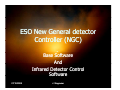
ESO New General detector
Controller (NGC)
Base Software
And
Infrared Detector Control
Software
07/10/2008
J. Stegmeier
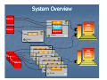
System Overview
Detector
4 - ADC
Up
NGC
LLCU
(Linux)
Cl k/Bi
Clock/Bias
Driver
Detector
Sequencer
Up
[N] - ADC
Down
Down
FEB
AQ
[N] - ADC
Up
2 3
Detector
Detector
Detector
Detector
Detector
Detector
Up
[N] - ADC
Down
2 3 [N] - ADC
Up
Down
2 3 [N] - ADC
Up
Down
2 3 [N] - ADC
Up
Down
2 3
Up
[N] - ADC
Down
Down
AQ
NGC
LLCU
(Linux)
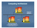
Computing Architecture
IWS
(
(Linux/
/
HP)
Instrument LAN
Fast Ethernet/
Gigabit--Ethernet
Gigabit
NGC
LLCU
(Linux)
…
With the current Linux
Linux--PC model
we can achieve 200 Mbytes/s
sustained input datadata-rate with coco-adding
(double correlated read
read--out)
NGC
LLCU
(Linux)
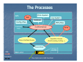
The Processes
IWS
Error-System
GUI
Config.-Files
D t b
Database
FITS-Files
Command/
Reply
Control Server
Device Driver
Commands
NGC LLCU
RTD
Acquisition Process
(Pre-Processing, Sorting,…)
Driver-Interface-Process
Data
Log-System
PCI-Bus
Interface
Fiber-Optic-Link to NGC Front End
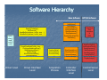
Software Hierarchy
Base Software
open()
()
close()
read()
write()
ioctl()
Reset()/Initialize()
SetTimeout()
ReadBuffer(address, buffer, size, …)
WriteBuffer(address, buffer, size, …)
SingleDmaRead(buffer, size
SingleDmaRead(buffer
size,…))
ConfigureSustainedDma()
StartSustainedDma()
WaitForData()
AbortSustainedDma()
GetDmaStatus()
…
Di
Driver
Level
L
l
SetVoltage()
GetVoltage()
SetClockPattern()
GetClockPattern()
StartSequencer()
StopSequencer()
Enable/DisableADC()
GetStatus()
…
Driver
D
i
Interface
I t f
Level
CaptureData()
ProcessData()
TransferData()
…
Acquisition
A
i iti
Process
StartAcquisition()
StopAcquisition()
RequestImage()
ReceiveImage()
…
Controller
C
t ll
Interface
Level
OPT/IR Software
Graphical
User
Interface
&
RTD
ReadConfigFile()
SetReadoutMode()
d
d ()
SetupExposure()
StartExposure()
AbortExposure()
CreateFitsFile()
UpdateDatabase()
DisplayImage()
…
Control
C
t l Server
S
Level
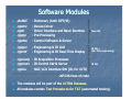
Software Modules
dicNGC
ngcdrv
ngcb
ngcpp
ngcdcs
-
ngcgui
ngcrtd
- Engineering & IR GUI
- Engineering & IR RealReal-Time Display
Dictionary (both OPT/IR)
Device Driver
Driver Interface and Basic Routines
Pre
Pre--Processing
Control Software & Server
ngciracq - IR Acquisition Processes
ngcircon - IR Control SW & Server
ngclcu
- NGC
NGC--LCU Interface SW (IR, for VLTI)
Base SW
IR SW +
Opt. SW (engineering)
IR SW
205726 lines of code
Th modules
The
d l will
ill be
b part off the
h VLTSW Releases.
Releases
R l
.
All modules contain Test Procedures for TAT (automated testing).
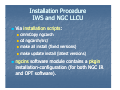
Installation Procedure
IWS and
d NGC LLCU
Via installation scripts:
scripts:
cmmCopy ngcarch
cd ngcarch/
ngca ch/
ngcarch
ch/src
ssrc/
c/
c/
make all install (fixed versions)
make
k update
d t iinstall
t ll (latest
(l t t versions)
i
)
ngcins
g
software module contains a p
pkgin
g
installation--configuration (for both NGC IR
installation
and OPT software).
)
Installation Procedure
D i Driver
Device
Di
Retrieve the driver module from the archive ((if not yet
y done):
)
Login as “root”
root to continue the installation (Attention
(Attention:: use telnet or
“su –” to ensure proper root session):
/usr
usr/local/bin/
/local/bin/ngcdrv_load
ngcdrv_load
/usr
usr/local/bin/
/local/bin/ngcdrv_unload
ngcdrv_unload
Add the following line to the file “/etc/
“/etc/rc.local
rc.local”” to load the driver at
boot--time:
boot
cd /tmp
tmp//ngcdrv
ngcdrv//src
make all install
Now you can load/unload the driver with:
cmmCopy ngcdrv
cp –r ngcdrv /tmp
/usr
usr/local/bin/
/local/bin/ngcdrv_load
ngcdrv_load
The device driver creates two independent devices:
“/dev/ngc
“/dev/
ngc<
<i>_com” and “/dev/
“/dev/ngc
ngc<
<i>_dma
>_dma”.
”.
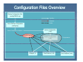
Configuration Files Overview
Startup Configuration Sets
(xxdcfgCONFIG.cfg)
Specifies…
Executes…
Reads…
Server Startup Configuration
(xxdcfg.cfg)
System Configuration
(.cfg)
Server Command Line Options
Control Server
Voltages (.v)
Detector Configuration
(.dcf)
Clock-Patterns (.clk)
IR-Applications
Seq.-Programs (.seq)
Startup Procedure
Startup tools:
[other options] for
f maintenance (verbose mode etc.) or ffor overriding the
keywords defined in the Startup
Startup--Configuration
Configuration--Set.
Set.
The control server startup configuration is described by a unique name
(configuration--set name).
(configuration
The <name> refers
efe s to the name of a Startup
Sta
Startupt p-Configuration
Config
Configurationation-Set which
hich is defined
in the main configuration file:
$INS_ROOT/SYSTEM/COMMON/CONFIGFILES/xxdcfgCONFIG.cfg
The Startup
Startup--Configuration
Configuration--Set describes the Startup
Startup--Configuration
Configuration--File and
some administrative
d i i t ti options:
ti
ngcdcsStartServer <configuration<configuration-set name> [[--gui
gui]] [other options]
ngcdcsStopServer <configuration<configuration-set name>
ngcdcsStartGui <configuration<configuration-set name> (only GUI)
CONFIG.SET1.NAME "KMDCS";
CONFIG.SET1.DICT "NGCCON";
CONFIG.SET1.FILE1 "kmdcfg.cfg";
CONFIG.SET1.PERM1 664;; # all
CONFIG.SET1.BACKUP T;
CONFIG.SET1.LOG
T;
The StartupStartup-Configuration
Configuration--File defines the server startup options - e.g. auto
auto-online, autoauto-start, database
database--point (if not default), server instance and the
controller
t ll electronics
l t i system
t
configuration
fi
ti file
fil (i.e.
(i HWHW-configuration)
fi
ti ) to
t b
be
loaded at startup.
Startup Procedure
Startup--Configuration
Startup
Configuration--File
File::
# Control server name
DET.CON.SERVER ""ngcdcsEvh
ngcdcsEvh";
";
# Database point
DET.CON.DATABASE ""ngcdcs
ngcdcs";
";
# Instance label for server and OLDB
DET.CON.INSTANCE "";
# HW system
y
configuration
g
file
DET.CON.SYSCFG "NGCIRSW/my_ngc.cfg";
# Startup mode (NORMAL, HWHW-SIM, LCULCU-SIM)
DET.CON.DFEMODE "HW
"HW--SIM";
# Go online after start
DET.CON.AUTONLIN F;
# AutoAuto-start at online
DET.CON.AUTOSTRT F;
# Enable subsub-system status polling
DET.CON.POLL T;
# Detector system index (DETi.XXX)
DET.CON.DETIDX 1;
# Dictionaries to load for this detector system
DET CON DICT "NGCDCS";
DET.CON.DICT
# GUI name
DET.CON.GUI ""ngcgui
ngcgui";
";
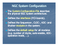
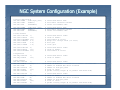
NGC System Configuration
The System
System--ConfigurationConfiguration-File describes
the physical NGC system architecture
architecture.
Defines the interfaces (PCI
(PCI--boards).
Defines the SequencerSequencer-, CLDC
CLDC--, ADC
ADC-- and
Shutter--modules in the system.
Shutter
system
Defines the default setup for all modules
(e.g. number of clocks, autoauto-enable, ADCADCoperation mode, …).
NGC System Configuration (Example)
# Device description
DET.DEV1.NAME
"/dev/ngc0_com";
DET.DEV1.HOST
"$HOST";
DET.DEV1.ENV
"$RTAPENV";
# associated device name
# host where interface resides
# server environment name
DET.DEV2.NAME
DET.DEV2.HOST
DET.DEV2.ENV
# associated device name
# host where interface resides
# server environment name
"/dev/ngc1_com";
"$HOST";
"$RTAPENV";
# CLDC modules
DET.CLDC1.DEVIDX
DET.CLDC1.ROUTE
DET.CLDC1.AUTOENA
DET.CLDC1.MARGIN
DET.CLDC1.DCGN
DET.CLDC1.CLKGN
1;
"2";
"T";
0.2;
2.0;
1.0;
#
#
#
#
#
#
DET.CLDC2.DEVIDX
DET.CLDC2.ROUTE
DET.CLDC2.AUTOENA
2;
"2";
"T";
# associated device index
# route to module
# auto-enable at online
# Sequencers
DET.SEQ1.DEVIDX
DET.SEQ1.ROUTE
1;
"2";
# associated device index
# route to module
# ADC modules
DET.ADC1.DEVIDX
DET ADC1 ROUTE
DET.ADC1.ROUTE
DET.ADC1.NUM
DET.ADC1.BITPIX
DET.ADC1.FIRST
DET.ADC1.PKTCNT
1;
"2"
"2";
4;
16;
"T";
1;
#
#
#
#
#
#
associated device index
route
t t
to module
d l
number of enabled ADC units on board
number of bits per pixel
first in chain
packet routing length (# of packets from down-link)
DET.ADC2.DEVIDX
DET.ADC2.ROUTE
2
DET.ADC2.NUM
DET.ADC2.BITPIX
DET.ADC2.FIRST
DET.ADC2.PKTCNT
1;
"5,2";
5 2
32;
16;
"F";
0;
#
#
#
#
#
#
associated device index
route to module
d l
number of enabled ADC units on board
number of bits per pixel
first in chain
packet routing length (# of packets from down-link)
associated device index
route to module
auto-enable at online
margin for voltage check (in volts)
bias gain
clock gain
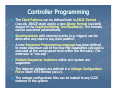
Controller Programming
The Clock
Clock--Patterns can be defined both in ASCII
ASCII--Format
(xxx.clk, IRACE
IRACE--style) and in a new Binary Format (xxx.bclk,
output
p of the Graphical
p
Editing
g Tool BlueWave).
BlueWave)). The formats
can be converted automatically.
Synchronization with external events (e.g. trigger) can be
done
do
ea
after
te a
anyy state in a
any
y cclockclock
oc -patte
pattern.
A new Sequencer Programming Language has been defined
to make maximum use of the new HW capabilities (all code is
executed at the same speedspeed-level within the firmware)
firmware). File
extension is “xxx.seq”.
Multiple Sequencer Instances within one system are
supported.
supported
The detector voltages are defined in a Voltage Configuration
File in Short
Short--FITS format (xxx.v).
The voltage configuration files can be loaded to any CLDC
instance in the system.
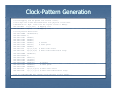
Clock--Pattern Generation
Clock
# Clock mapping (can be spread over several lines).
# This maps the clocks described below onto physical clock lines.
# Mechanism is: Phys. clock line for logical clock n = MAP[n].
DET.CLK.MAP1 "1,2,3,33";
# Mapping list
DET CLK MAP2 "37
DET.CLK.MAP2
37,4
4";
;
# Mapping list
# Clock pattern definitions
DET.PAT1.NAME “FrameStart";
DET.PAT1.NSTAT 5;
DET.PAT1.CLK1 "00000";
DET.PAT1.CLK2 "00000";
DET.PAT1.CLK3 "00000";
DET.PAT1.CLK4 "00000";
DET.PAT1.CLK5 "00110";
DET.PAT1.CLK6 "00000";
DET.PAT1.DTV
"2,2,2,2,2";
DET.PAT1.DTM
"0,0,0,0,0";
DET.PAT2.NAME
DET.PAT2.NSTAT
DET.PAT2.CLK1
DET.PAT2.CLK2
DET.PAT2.CLK3
DET.PAT2.CLK4
DET.PAT2.CLK5
DET.PAT2.CLK6
DET.PAT2.DTV
DET.PAT2.DTM
# Convert
# Start pulse
# Dwell-Time vector
# Dwell-Time modification flags
“ReadPix";
6;
"000111";
“111000";
"000000";
"000010";
;
"000000";
"000000";
"5,5,5,5,5,5";
"1,1,1,1,1,1";
# Convert
# Start pulse
# Dwell-Time vector
# Dwell-Time modification flags
# Up to ngcdcsSEQ_MAX_PAT (=2048) clock patterns in this format...
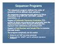
Sequencer Programs
The sequencer program defines the order of
execution of the defined clock patterns.
The
h sequencer programs are fully
f ll driven
di
by
b Setup
S
Parameters (e.g. DET.DIT, DET.NDIT, window
parameters, …).
Support of Arithmetic Expression Evaluation (TCL
(TCL-syntax) to derive any program
program--loop parameter from the
setup parameters and to compute attributes like
exposure time
ti
estimations
ti ti
and
d minimum
i i
DIT.
DIT
Support of Sub
Sub--Routines and Include
Include--Files to minimize
the code length.
The program complexity can be scaled:
Simply do not “USE” any setup parameter.
Simply omit the “SCRIPT”
SCRIPT part for arithmetic expression
evaluation.
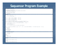
Sequencer Program Example
# PATTERN DECLARATION
# PARAMETER DECLARATION
USE DET.NDIT DET.SEQ.DIT DET.DITDELAY DET.NDITSKIP
# SUBROUTINE DECLARATION
SUBRT RESET DELAY FRAME
# EVALUATE
SCRIPT
if {$svar(DET.NDIT) <= 0} {
set svar(DET.NDIT) 1
}
set tr [expr {$time_r(RESET) / 1000.0}]
set tf [expr {$time_r(FRAME) / 1000.0}]
set td [expr {$time_r(DELAY) / 1000.0}]
set svar(DET.SEQ.MINDIT) $tf
set t1 [expr {($svar(DET.NDIT) + $svar(DET.NDITSKIP))}]
set svar(delFac) [expr {($svar(DET.SEQ.DIT) - $tf) / $td}]
set svar(ditDelay) [expr {($svar(DET.DITDELAY) / $td)}]
if {$svar(delFac) < 0} {
set svar(delFac) 0
set svar(DET.SEQ.DIT) $svar(DET.SEQ.MINDIT)
}
set svar(DET.SEQ.EXPTIME) [expr {($t1 * ($tr + $svar(DET.DITDELAY) + $svar(DET.SEQ.DIT) + $tf))}]
SCRIPT_END
# EXECUTE
LOOP INFINITE
JSR RESET
JSR DELAY $ditDelay
JSR FRAME
JSR DELAY $delFac
JSR FRAME
END
RETURN
# SUBROUTINES
RESET:
INCLUDE "Hawaii2RGReset.seq"
DELAY:
INCLUDE "Hawaii2RGDelay.seq"
FRAME:
INCLUDE "Hawaii2RGFrame.seq"
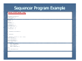
Sequencer Program Example
Hawaii2RGFrame.seq:
#PATTERN DECLARATION
FRAME_START = 1
ROW_START = 2
PIXEL = 3
RESET = 4
DELAY = 5
TRIGGER = 6
DUMMYPIXEL = 7
PIXELRESET = 8
VERTICALCLOCK = 9
EN_UNBUF_B = 10
MAINRESETB = 11
# PARAMETER DECLARATION
# EVALUATE
# EXECUTE (readout of full frame)
EXEC TRIGGER 1
EXEC MAINRESETB 1
EXEC EN_UNBUF_B 1
EXEC FRAME_START 1
LOOP 2048
EXEC ROW_START 1
EXEC DUMMYPIXEL 2
EXEC PIXEL 64
#EXEC DUMMYPIXEL 8
END
EXEC VERTICALCLOCK 1
RETURN
Detector Voltage Setup
# Offsets:
DET.CLDC.CLKOFF 10.0;
DET.CLDC.DCOFF 10.0;
# Global clock voltage offset
# Global DC voltage offset
# Clock Voltages:
DET.CLDC.CLKHINM1
DET.CLDC.CLKHI1
DET.CLDC.CLKHIGN1
DET.CLDC.CLKHIRA1
"clk1Hi";
3.000;
1.0;
"[-9.000, 9.000]";
#
#
#
#
Name
Setup value
Gain (optional)
Allowed range
DET.CLDC.CLKLONM1
DET.CLDC.CLKLO1
DET.CLDC.CLKLOGN1
DET.CLDC.CLKLORA1
"clk1Lo";
0.000;
1.0;
"[-9.000, 9.000]";
#
#
#
#
Name
Setup value
Gain (optional)
Allowed range
#
#
#
#
Name
Setup value
Gain (optional)
Allowed range
# Up to 16 clock voltages like this ...
# DC Voltages:
DET.CLDC.DCNM1
DET.CLDC.DC1
DET.CLDC.DCGN1
DET CLDC DCRA1
DET.CLDC.DCRA1
"DC1";
0.000;
1.0;
"[-9
[ 9.000,
000 9
9.000]
000]";
;
# Up to 20 DC-voltages like this ...
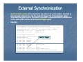
External Synchronization
Synchronization points can be inserted at any place in any clock pattern executed by
the sequencer program (i.e. set the “wait“wait-for
for--trigger” bit in the particular state).
When reaching such a point, the pattern execution is suspended after the dwelldwell-time
of this state until the arrival of an external trigger signal
signal..
Example:
# Clock mapping (can be spread over several lines).
# This maps the clocks described below onto physical clock lines.
# Mechanism is: Phys. clock line for logical clock n = MAP[n].
DET.CLK.MAP1 "1,2,3,33";
# Mapping list
DET.CLK.MAP2 "37,4,61";
# Mapping list
# Clock pattern definitions
DET.PAT1.NAME “FrameStartSync";
Wait for Trigger
DET.PAT1.NSTAT 5;
DET.PAT1.CLK1 "00000";
DET.PAT1.CLK2 "00000";
DET.PAT1.CLK3 "00000";
DET.PAT1.CLK4 "00000";
# Convert
DET.PAT1.CLK5 "00110";
# Start pulse
DET.PAT1.CLK6 "00000";
DET.PAT1.CLK7 “10000";
# Sync
DET.PAT1.DTV
"2,2,2,2,2"; # Dwell-Time vector
DET.PAT1.DTM
"0,0,0,0,0"; # Dwell-Time modification flags
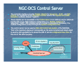
NGC--DCS Control Server
NGC
The controller interface provides Modular Objects for Sequencer
Sequencer--, CLDC
CLDC-- and ADC
ADC-Control, for interfacing to the Acquisition Process and for the Asynchronous Data
Reception (software module “ngcdcs”).
These objects can be assembled in the Control Server in an arbitrary way to reflect all
functionality of any NGC hardware configuration (i.e. Multiple Instances of
Sequencer--, CLDC
Sequencer
CLDC--, ADCADC-modules and any number of Acquisition Processes). The
module configuration is done through the System Configuration File.
File.
The control server can be used as NGC
NGC--HW Control SubSub-System of the NGCOSW
NGCOSW.
That is the maximum degree of communality as the same compiled and linked object
is used by both applications to access the HW. It can be configured at RunRun-Time for
the one or the other purpose.
IWS
Config.-Files
Command/
Reply
GUI
Error-System
Log-System
Database
FITS-Files
C t l Server
Control
S
Infrared
Applications
Database
The file ngcdcs.db contains the database branch definition for the control
server. This file has to be included in the DATABASE.db file of the CCS
environment.
The
h following
f ll i macros can be
b defined
d fi d before
b f
each
h inclusion:
i l i
#define ngcdcsINSTANCE ngcdcs_myInstance
#define ngcdcsROOT :Appl_data
Appl_data:...:
:...:myPoint
myPoint
#include “ngcdcs.db
“ngcdcs.db””
The basic structure of the database is as follows:
--o
-o <alias><ngcdcsINSTANCE
<alias><ngcdcsINSTANCE >--
|---o
o
|---o
o
|---o
o
|---o
o
|---o
o
|---o
o
|---o
o
|---o
o
|---o
o
system
exposure
mode
guiding
chopper
seq_<
seq_<ii>
cldc_<
cldc_<ii>
adc_
adc
_<i>
acq_<
acq_<ii>
(NGC system parameters)
(exposure parameters)
(read--out mode p
((read
parameters))
(guiding parameters)
(chopper interface)
(sequencer parameters)
(CLDC parameters)
((ADC
C module
odu e parameters)
pa a ete s)
(acquisition module parameters)
The branches for the SequencerSequencer-, CLDC
CLDC--, ADCADC-, and Acquisition
Acquisition-- modules
are indexed. One branch will be created per module.
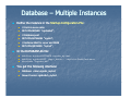
Database – Multiple Instances
Define the instance in the Startup
Startup--Configuration
Configuration--File:
File:
# Database point
DET.CON.DATABASE ""ngcdcs
ngcdcs";
";
# Instance label for server and OLDB
DET.CON.INSTANCE "myInst
"myInst";
";
In the DATABASE.db file:
# Control server name
DET CON SERVER "ngcdcsEvh
DET.CON.SERVER
"ngcdcsEvh
ngcdcsEvh";
";;
#define ngcdcsINSTANCE ngcdcs_myInst
ngcdcs myInst
#define ngcdcsROOT :Appl_data
Appl_data:...:
:...:myPointForMyInstance
myPointForMyInstance
#include "ngcdcs.db
"ngcdcs.db"
"
You get the following interface:
Database: <alias>
<alias>ngcdcs_myInst
ngcdcs_myInst
Server Process: ngcdcsEvh_myInst
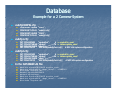
Database
Example for a 2 CameraCamera-System
xxdcfgCONFIG.cfg:
DET.CON.SERVER
DET.CON.DATABASE
DET.CON.INSTANCE
DET.CON.SYSCFG
"ngcdcsEvh
ngcdcsEvh";
";
# -> ngcdcsEvh_cam1
"ngcdcs
ngcdcs";
";
# -> <alias>ngcdcs_cam1
"cam1";
"NGCIRSW/xxdcfgCam1.cfg"; # NGC HWHW-system configuration
xxdcfg2 cfg:
xxdcfg2.cfg:
"CAM1";
CAM1 ;
"xxdcfg1.cfg";
"CAM2";
"xxdcfg2.cfg";
xxdcfg1.cfg:
g
g
CONFIG.SET1.NAME
CONFIG.SET1.FILE1
CONFIG.SET2.NAME
CONFIG.SET2.FILE1
DET.CON.SERVER
DET.CON.DATABASE
DET.CON.INSTANCE
DET.CON.SYSCFG
"ngcdcsEvh
ngcdcsEvh";
";
# -> ngcdcsEvh_cam2
"ngcdcs
ngcdcs";
";
# -> <alias>ngcdcs_cam2
"cam2 ";
"NGCIRSW/xxdcfgCam2.cfg"; # NGC HWHW-system configuration
I th
In
the DATABASE.db
DATABASE db file:
fil
#define ngcdcsINSTANCE ngcdcs_cam1
#define ngcdcsROOT :Appl_data
Appl_data:...:CAMERA1
:...:CAMERA1
#include "
"ngcdcs.db
ngcdcs.db"
"
#undef ngcdcsINSTANCE
#undef ngcdcsROOT
#define ngcdcsINSTANCE ngcdcs_cam2
#define ngcdcsROOT :Appl_data
Appl_data:...:CAMERA2
:...:CAMERA2
#include "
"ngcdcs.db
ngcdcs.db"
"
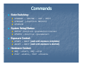
Commands
State Switching:
System Setup/Status:
SETUP –function <parameter><value>
STATUS –function <parameter>
Exposure Control:
STANDBY – ONLINE – OFF – EXIT
SIMULAT [[-function HW|LCU]
STOPSIM
START – WAIT (wait until exposure completes)
ABORT
O
– WAIT ((wait
at u
until
t e
exposure
posu e iss abo
aborted)
ted)
Hardware Control:
SEQ -start, SEQ -stop
CLDC –enable, CLDC -disable
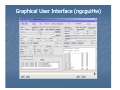
Graphical User Interface ((ngcguiHw
ngcguiHw))
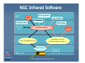
NGC Infrared Software
IWS
Error-System
GUI
Config.-Files
D t b
Database
FITS-Files
Command/
Reply
Control Server
Device Driver
Commands
NGC LLCU
RTD
Acquisition Process
(Pre-Processing, Sorting,…)
Driver-Interface-Process
Data
Log-System
PCI-Bus
Interface
Fiber-Optic-Link to NGC Front End
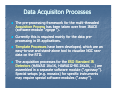
Data Acquisiton Processes
The pre
pre--processing framework for the multimulti-threaded
Acquisition Process has been taken over from IRACE
(software module “ngcpp ”).
Currently this is required mainly for the data pre
pre-processing in IR applications
applications.
Template Processes have been developed, which are an
easy--to
easy
to--use and stand
stand--alone tool to visualize NGC raw
raw-data on the RTD.
The acquisition
q
processes
p
for the ESO Standard IR
Detectors (HAWAII 1Kx1K, HAWAII2HAWAII2-RG 2Kx2K, …) are
assembled in a separate software module (“ngciracq ”).
Special
p
setups
p (e.g.
( g mosaics)) for specific
p
instruments
may require special software modules (“xxacq ”).
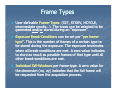
Frame Types
User-definable Frame
UserFrame--Types (DIT, STDEV, HCYCLE,
intermediate results…). The types can be selected to be
generated and
and//or stored during an “exposure”.
Exposure BreakBreak-Conditions can be set per “per
“per frame
frame-type”.
type
”. This is the number of frames of a certain type to
be stored during the exposure. The exposure terminates
when all breakbreak-conditions are met. A zero value indicates
to store as much as possible frames of that type until all
other breakbreak-conditions are met.
Individual SWSW-Windows per frame
frame--type. A zero value for
the dimension (nx, ny) indicates that the full frame will
be requested from the acquisition process.
process
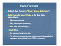
Data Formats
Default data format is “Binary
“Binary Image Extension”.
Extension”.
D t C
Data
Cubes
b for
f Burst
B
Burstt-Mode
M d or for
f ffastt d
data
t
acquisitions.
Minimum overhead
May require postpost-processing
One cube per frame
frame--type
Single files
For detector tests in the lab
To optimize merging process: start merging already before
exposure is completed (e
(e.g.
g VISTAVISTA-instrument).
instrument)
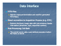
Data Interface
FITS--Files
FITS
Direct connection to Acquisition Process (e.g.
(e g RTD)
W it for
Wait
f exposure ttermination
i ti and
d read
d the
th generated
t d
FITS--file(s).
FITS
Retrieve the binary image data with just minimum header
information (dimension, type, sequential number).
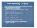
Post--Processing CallPost
Call-Back
The control server calls a useruser-defined procedure before
the frame is stored.
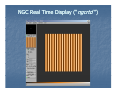
NGC Real Time Display (“ngcrtd ”)
Post--Processing Call
Post
Call--Back
The post
post--processing call
call--back is executed whenever a new data frame is received by
the data acquisition thread of the control server:
int PostProcCB(void
PostProcCB(void *buffer, ngcdcs_finfo_t *finfo,
finfo, eccsERROR *error);
The ngcdcs_finfo_t structure finfo contains all information for the buffer:
int type;
char name[64];
int fcnt
fcnt;
;
int scaleFactor
scaleFactor;
;
int bitPix
bitPix;
;
int sx
sx;
;
int sy
sy;
;
int nx
nx;
;
i t ny
int
ny;
;
double crpix1;
double crpix2;
int detIdx
detIdx;
;
int expCnt
expCnt;
;
char utc
utc[64];
[64];
[
];
ngcdcsCUBE *cube;
-
Unique frame type
Unique frame name
Frame counter
Scaling factor to be applied to normalize
Bits per pixel as defined in the FITS
FITS-standard
Lower left corner (x
(x-direction)
Lower left corner (y
(y-direction)
Dimension in x
x-direction
Di
Dimension
i
i
in yy-direction
di
ti
Reference pixel in x
x-direction
Reference pixel in y
y-direction
Detector index (for mosaics)
Exposure counter for this type
Time when frame was ready
y in the p
pre-p
preprocessor
Data cube object to be used for storing to a cube
The postpost-processing call
call--back may return one of the following values:
ngcbSUCCESS
ngcbFAILURE
g
ngcbSKIP
- Successful operation
- Failure ((add an error string
g to the error stack))
- Successful operation - but skip all further actions on the frame (no storage to file,...)
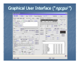
Graphical User Interface (“ngcgui ”)
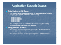
Application Specific Issues
State Switching CallCall-Backs
The following callcall-backs are provided when the server state changes (i.e. upon
reception of an ONLINE, STANDBY or OFF command):
ccsCOMPL_STAT
ccsCOMPL_STAT
ccsCOMPL_STAT
ccsCOMPL STAT
ccsCOMPL_STAT
ccsCOMPL_STAT
ccsCOMPL_STAT
OnlineCB1();
OnlineCB2();
StandbyCB1();
StandbyCB2();
OffCB1();
OffCB2();
The xxxCB1() functions are called before the state changes, the xxxCB2()
functions are called after internal state switching.
g
Setup/Status CallCall-Backs
The following callcall-backs are provided upon reception of a SETUP command:
ccsCOMPL_STAT SetupCB1(char **list, vltINT32 *size);
ccsCOMPL_STAT SetupCB2();
The following callcall-back is provided upon reception of a STATUS command:
int LookupCB(const
LookupCB(const char *name, char *value);
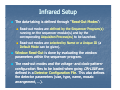
Infrared Setup
The datadata-taking is defined through “Read
“Read--Out Modes
Modes”:
”:
Read-out modes are defined by the Sequencer Program(s)
Readrunning on the sequencer module(s) and by the
corresponding Acquisiton Process(
Process(es
es)) to be launched.
Read-out modes are selected by Name or a Unique ID (a
ReadDefault Mode can be given).
Window
Wi
d
Read
ReadR d-Out
O t is
i done
d
by
b evaluating
l ti the
th window
i d
parameters within the sequencer program.
The readread-out modes and the voltage
voltage-- and clockclock-pattern
pattern-configuration files to be loaded when going ON
ON--LINE are
defined in a Detector Configuration File.
File. This also defines
the detector parameters (size, type, name, mosaic
arrangement, …).
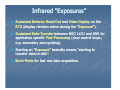
Infrared “Exposures”
Sustained Detector ReadRead-Out and Video Display on the
RTD ((display
p y remains active during
g the “Exposure
“Exposure”).
p
”).
)
Sustained DataData-Transfer between NGCNGC-LLCU and IWS for
application specific Post
Post--Processing (slow control loops,
e.g. secondary autoauto-guiding).
Starting an “Exposure
“Exposure”” basically means “starting to
transfer data to disk”.
Burst--Mode for fast raw data acquisition.
Burst
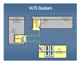
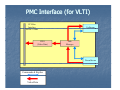
VLTI--System
VLTI
LCU
MVME6100
(VxWorks)
PCI
Interface
NGC LLCU
(Li
(Linux)
)
PMC
Interface
NGC
Detector
Front-End
PMC Interface (for VLTI)
PCI-Bus
Interface
64 Bit/33 Mhz
FIFO
(Video Data)
UpStream
p
Link
Manager
DownStream
Commands & Replies
Video-Data
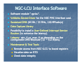
NGC--LCU Interface Software
NGC
Software module “ngclcu”.
VxWorks Device Driver for the NGC PMC Interface card.
Sustained DMA (64 Bit / 33 MHz, 128 MPixels/s)
MPixels/s)
Data Capture Library
Possibility to install a User
User--Defined Interrupt Service
Routine (to minimize the latency).
Latency: min. 4 µs, max. 6 µs depending on the
Latency:
configurable DMA
DMA--Blocksize (32 – 512 Bytes).
Maintenance & Test Tools
Remote access from NGCNGC-LLCU to board registers
Visualize data on RTD
Check data integrity
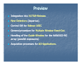
Preview
Integration into VLTSW
VLTSW--Release.
Release.
New Detectors (Aquarius).
Control SW for Sidecar ASIC.
ASIC.
General procedure for Multiple Window ReadRead-Out.
Out.
Handling of the Guide
Guide--Window for the HAWAII2HAWAII2-RG
array (parallel exposures).
Acquisition processes for AO
AO--Applications
Applications..
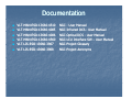
Documentation
VLT-MANVLTMAN-ESOESO-13660
13660--4510
VLT--MAN
VLT
MAN--ESO
ESO--13660
13660--4085
VLT--MANVLT
MAN-ESOESO-13660
13660--4086
VLT--MANVLT
MAN-ESOESO-13660
13660--4560
VLT--LIS
VLT
LIS--ESO
ESO--13660
13660--3907
VLT--LIS
VLT
LIS--ESOESO-13660
13660--3908
NGC - User Manual
NGC Infrared DCS - User Manual
NGC Optical DCS - User Manual
NGCNGC-LCU Interface SW – User Manual
NGC Project Glossary
NGC Project Acronyms