1
THE NEW GENERAL
DETECTOR
CONTROLLER - NGC/OPT
Claudio Cumani
Instrumentation SW Workshop 2008 - 2008, October 7
Differences btw IR and OPT detector controllers: intrinsic
2
“Exposure” handling
¾
Optical
Rigid scheme for exposures (wipe - integrate - [“move charges on
detector while integrating”] - read ).
A ti intervention
Active
i t
ti off the
th control-server
t l
d i th
during
the exposure is
i
required (application of new voltages in each state).
“Active” interface to different kinds of shutter controllers (open/close,
status check, open/close delays, etc.).
¾
Infrared
Detector continuously read-out (infinite loop).
Starting
g an exposure
p
= starting
g transfer and storage
g of data. Once
exposure is started, control server mainly reacts passively on
incoming data-frames.
No “active” interface to external devices (interfaces through trigger
signals,
g
, e.g.,
g , for nodding).
g)
Differences btw IR and OPT detector controllers: intrinsic
3
Data handling
g
¾
Infrared
Computationally intensive different data pre-processing,
read-out mode dependent.
¾
Optical
Detector
D
t t read-out
d t just
j t once att the
th end
d off an exposure.
The only processing to be done is pixel sorting and offset
calibration (centroiding and bias-subtraction on request).
Differences btw IR and OPT detector controllers: historical
4
optical detector controllers are requested to
interface/control also devices which are not – strictly
speaking - part of the detector, like vacuum and
temperature control (and write values in FITS file
header)
Optical NGC needs its own software
5
¾
Base software common to Infrared and
p
detectors to interface the
Optical
hardware (thanks Joerg)
¾
At higher
A
hi h llevel:l
NGCIRSW and NGCOSW
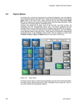
NGC Software Environment
6
Instrument
Software
Configuration
Files
FITS Files
Commands/Replies
Data
NGCOSW
Data
RTD
Setup Files
Dictionary
Online
database
Log
System
Error
System
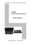
NGCOSW Processes
7
Commands
Replies
IWS
Image
Transfer
Client
System
Control
FITS File
Memory
(RTD)
Image
Transfer
Server
Exposure
Control
Shutter
DFE
Server
LLCU
Operational Modes
8
¾
¾
Normal mode: the NGC detector electronics is
connected.
Hardware-Simulation
Hardware
Simulation mode: the NGC
detector electronics is simulated.
The FIERA LCU-Simulation
LCU Simulation mode is equivalent to
Hardware-Simulation.
The NGCOSW can either be distributed on both the IWS
and the NGC LLCU or run completely on one of the two
platforms.
Optical “Exposures Modes”
9
Exposure Modes define the set of
voltages, clock patterns and sequences to
be applied to the different “steps”
steps of an
exposure (wipe, integrate, read).
Same approach of FIERA
Exposure Modes are defined in the
d t t Configuration
detector
C fi
ti Fil
File (diff
(differentt ffor
each instrument)
Temperature/vacuum monitoring
10
3 options under discussion:
Via NGC LLCU serial port (à la FIERA)
Via standard LCU (à la IRACE)
Via
Vi S
Serial-to-ethernet
i l t th
t adapter
d t
NGCOSW code
11
NGCOSW code generated using the wsf (workstation
software framework) tool developed by SDD
See: Andolfato L., Karban R., “Workstation Software
Framework”, article for SPIE 2008 “Astronomical
Telescopes and Instrumentation”
Instrumentation Conference,
Conference Marseille,
Marseille
Jun 23-28, 2008
NGCOSW overview
12
ngcocon - The NGC System Coordination module for optical applications. This
includes all required scripts for system startup and shutdown.
ncgoctr - The NGC Exposure Control module for optical applications.
ncgoexp - The NGC
GC Exposure Coordination
C
module for
f optical applications.
ncgoits - The NGC Image Transfer Server module for optical applications.
ncgoitc - The NGC Image Transfer Client module for optical applications.
ngcoui - Engineering GUI used for direct system interaction and data acquisition.
The modules will be part of the VLTSW Releases.
All modules
d l contain
i Test
T
Procedures
P
d
f TAT (automated
for
(
d testing).
i )
Installation
13
NGCOSW is built on top of the NGCIRSW
Via installation scripts
Install NGCIRSW first (cmm module ngcarch)
cd <YOUR_SRC_DIR>; cmmCopy ngcarch; cd ngcarch/src/; make all install
Then install NGCOSW (cmm module ngcoarc)
cd <YOUR_SRC_DIR>; cmmCopy ngcoarc; cd ngcoarc/src/; make all install
ngcins software module contains a pkgin installation
installationconfiguration (for both NGC IR and OPT software):
cd <YOUR_SRC_DIR>; cmmCopy ngcins; pkginBuild ngcins
Configuration - environment
14
E i
Environment
t variables
i bl
NOTE : on the NGC-LLCU the environment variables are defined in the files
/etc/pecs/releases/000/etc/locality/apps-all.env
/etc/pecs/releases/000/etc/locality/apps-${HOST}.env
On the IWS you could define them in the same files or in
~/.pecs/apps-${HOST}.env
RTAPENV defines the name of the local online database environment
CCDLENV on the IWS defines the name of the remote online database
environment, on the NGC-LLCU it must be set to 0
CCDNAME defines the name of the detector camera
Configuration - system check
15
ngcoDcsOldb preliminary check:
Are the environment variables defined?
Is ACC server defined and running?
Are local and remote environments defined on the local computer and in
the ACC server?
Is scanning properly configured?
Is the user which shall run the software defined on the local and the remote
computer?
…
Configuration - oldb
16
C t the
Create
th environment:
i
t ngcoDcsOldb
D Oldb (different
(diff
t on IWS and
d LLCU)
On the IWS: ngcoDcsOldb -renv $CCDLENV -host IWS
NOTE: only template files DATABASE.db.NGCOSW and USER.db.NGCOSW
are generated: use them to edit DATABASE.db and USER.db
Example 1: Instrument controlling one camera, add in DATABASE.db:
#undef
#undef
#undef
#define
#define
#define
CCDNAME
ngcdcsINSTANCE
NGCROOT
CCDNAME <myCCDNAME>
ngcdcsINSTANCE ngcdcs_<myCCDNAME>
NGCROOT :Appl_data<:myPATH>:CCDNAME
Configuration - oldb
17
Example 2: Instrument controlling four cameras,
cameras add in DATABASE.db:
DATABASE db:
#undef
#undef
#undef
#undef
#undef
#undef
#undef
#undef
#undef
#undef
#define
#define
#define
#define
#define
#
#define
#define
#define
#define
#define
DCSNAME
CCDNAME
ngcdcsINSTANCE
CCDNAME2
ngcdcsINSTANCE2
CCDNAME3
ngcdcsINSTANCE3
CCDNAME4
ngcdcsINSTANCE4
NGCROOT
DCSNAME <INSTRUMENT>
CCDNAME <myCCDNAME>
ngcdcsINSTANCE ngcdcs_<myCCDNAME>
CCDNAME2 <myCCDNAME2>
ngcdcsINSTANCE2
g
ngcdcs
g
_<myCCDNAME2>
y
CCDNAME3 <myCCDNAME3>
ngcdcsINSTANCE3 ngcdcs_<myCCDNAME3>
CCDNAME4 <myCCDNAME4>
ngcdcsINSTANCE4 ngcdcs_<myCCDNAME4>
NGCROOT :Appl_data<:myPATH>:DCSNAME
Configuration - oldb
18
Once the DATABASE.db and USER.db files have been properly
edited on the IWS, generate the environment: in
$VLTDATA/ENVIRONMENTS/$RTAPENV/dbl run
make clean db
To initialize and start the environment run:
vccEnvInit
E I it -e $RTAPENV
vccEnvStart -e $RTAPENV
On the LLCU: ngcoDcsOldb -renv <IWS_RTAPENV> -host LLCU
Configuration - oldb
19
The basic structure of the database (on the IWS of a system with
just one camera and on the LLCU) is as follows:
--o <alias><CCDNAME>--
|--o
|--o
|--o
|--o
|--o
|--o
|--o
|--o
|--o
exposure (exposure state)
ngcdcs (device driver)
ngcocon (coordination process)
ngcoctr (control process)
ngcoexp (exposure handler)
ngcoitc (image transfer client)
ngcoits (image transfer server)
system (NGC system state)
wcs
(world coordinate system)
Configuration - oldb
20
On the IWS, the structure of the database of a system with more
cameras (e.g., 4) is as follows:
--o <alias><DCSDNAME>--
|--o
|--o
|--o
|--o
|--o
|--o
|--o
|--o
|--o
<camera1>
(first camera)
<camera2>
(second camera)
<camera3>
(third camera)
<camera4>
(fourth camera)
exposure (exposure state)
ngcocon (coordination process)
ngcoitc (image transfer client)
system (NGC system state)
wcs
(world coordinate system)
where <camera1>, …, <camera4> have the basic structure shown
before
Configuration – Instrument module
21
Install the instrument module (<xxdcfg>)
cmmCopy <xxdcfg>
cd <xxdcfg>/src;
f /
make all install
The instrument module <xxdcfg>
g contains
The voltages, patterns and sequences to drive the detector
The detector startup configuration file <xx>dcfgCONFIG.cfg and the
configuration
g
set <xx>dcfgCAMERA.cfg
g
g
Note: naming convention: <xx> instrument specific, d=detector,
g
g
cfg=configuration
Configuration – Instrument module
22
Configuration set keywords specific to optical systems
####################################################################
# CHIP description
####################################################################
DET.CHIP1.ID
DET.CHIP1.NAME
DET.CHIP1.DATE
DET.CHIP1.NX
DET.CHIP1.NY
DET.CHIP1.PRSCX
DET.CHIP1.PRSCY
DET.CHIP1.OVSCX
DET.CHIP1.OVSCY
DET.CHIP1.PSZX
1
DET.CHIP1.PSZY
DET.CHIP1.OUTPUTS
"SER-NO=053";
"Marlene";
"2006-11-22";
2048;
4096;
50;
0;
50;
0;
1
15.0;
0
15.0;
2;
#
#
#
#
#
#
#
#
#
#
#
#
Detector chip identification
Detector chip name
Date of installation [YYYY-MM-DD]
Physical active pixels in X
Physical active pixels in Y
Physical prescan pixels in X
Physical prescan pixels in Y
Physical overscan pixels in X
Physical overscan pixels in Y
Size
i
of pixel
i
i
in X (mu)
Size of pixel in Y (mu)
Number of outputs per chip
DET.CHIP1.X
DET.CHIP1.Y
DET.CHIP1.XGAP
DET CHIP1 YGAP
DET.CHIP1.YGAP
DET.CHIP1.RGAP
DET.CHIP1.INDEX
DET.CHIP1.LIVE
DET.CHIP1.TYPE
DET.CHIP1.PXSPACE
1;
1;
0.0;
0
0.0;
0
0.0;
1;
T;
CCD;
1E-6;
#
#
#
#
#
#
#
#
#
X location in array
Y location in array
Gap between chips along x (mu)
G
Gap b
between
t
chips
hi
along
l
Y (
(mu)
)
Angle of gap between chips
Chip index
Detector alive
The Type of detector chip
Pixel-Pixel Spacing
Configuration – Instrument module
23
Configuration set keywords specific to optical systems (cont.)
DET.CHIP1.OUT1.NAME
DET.CHIP1.OUT1.INDEX
DET.CHIP1.OUT1.ID
DET.CHIP1.OUT1.X
DET.CHIP1.OUT1.Y
DET.CHIP1.OUT1.READX
DET.CHIP1.OUT1.READY
"NO1";
1;
"IdO1";
1;
1;
-1;
-1;
#
#
#
#
#
#
#
Description of output
Output index
Output ID as from manufacturer
X location of output
Y location of output
Horizontal readout direction
Vertical readout direction
DET.CHIP1.OUT2.NAME
DET.CHIP1.OUT2.INDEX
DET.CHIP1.OUT2.ID
DET.CHIP1.OUT2.X
DET.CHIP1.OUT2.Y
DET CHIP1 OUT2 READX
DET.CHIP1.OUT2.READX
DET.CHIP1.OUT2.READY
"NO2";
2;
"IdO2";
2048;
1;
1
1;
-1;
#
#
#
#
#
#
#
Description of output
Output index
Output ID as from manufacturer
X location of output
Y location of output
H
Horizontal
i
t l readout
d t di
direction
ti
Vertical readout direction
Configuration – Instrument module
24
Configuration set keywords specific to optical systems (cont.)
####################################################################
# MODE description
####################################################################
DET.MODE1.NAME
DET.MODE1.DESC
DET.MODE1.TRIGGER
DET.MODE1.GAIN
DET.MODE1.BNDWTH
DET.MODE1.WREP
DET.MODE1.WCLDFIL1
DET.MODE1.WCLKFIL1
DET.MODE1.WPRGFIL1
DET MODE1 PREP
DET.MODE1.PREP
DET.MODE1.PCLDFIL1
DET.MODE1.PCLKFIL1
DET.MODE1.PPRGFIL1
DET.MODE1.DREP
DET.MODE1.DCLDFIL1
DET.MODE1.DCLKFIL1
DET MODE1 DPRGFIL1
DET.MODE1.DPRGFIL1
DET.MODE1.RREP
DET.MODE1.RCLDFIL1
DET.MODE1.RCLKFIL1
DET.MODE1.RPRGFIL1
DET.MODE1.ADCSAMPL
"Test1";
"Test mode 1";
F;
"";
"";
1;
"wipe1.v";
"wipe1.bclk";
"wipe1.seq";
1
1;
"preint1.v";
"preint1.bclk";
"preint1.seq";
0;
"";
"";
"";
;
1;
"read1.v";
"read1.bclk";
"read1.seq";
"-1,1";
#
#
#
#
#
#
#
#
#
#
#
#
#
#
#
#
#
#
#
#
#
#
Exposure mode name
Exposure mode description
Enable trigger
Gain used
Bandwidth used
Wipe sequence repetition number
Name of CLDCi FILE for wipe
Name of SEQi CLKFILE for wipe
Name of SEQi PRGFILE for wipe
P
Preint
i t sequence repetition
titi
number
b
Name of CLDCi FILE for preintegration
Name of SEQi CLKFILE for preintegration
Name of SEQi PRGFILE for preintegration
During int sequence repetition number
Name of CLDCi FILE during integration
Name of SEQi CLKFILE during integration
Name of SEQi PRGFILE during integration
Readout sequence repetition number
Name of CLDCi FILE for readout
Name of SEQi CLKFILE for readout
Name of SEQi PRGFILE for readout
ADC data sampling factors
Configuration – Instrument module
25
Configuration set keywords specific to optical systems (cont.)
DET.MODE1.OUTPUTS
DET.MODE1.ADC1.ADCS
1
"1";
# Number of outputs used for readout
# Outputs used for readout
DET.MODE1.OUT1.CHIP
DET.MODE1.OUT1.INDEX
DET.MODE1.OUT1.XIMA
DET.MODE1.OUT1.YIMA
DET.MODE1.OUT1.NX
DET.MODE1.OUT1.NY
DET.MODE1.OUT1.PRSCX
DET.MODE1.OUT1.PRSCY
DET.MODE1.OUT1.OVSCX
DET.MODE1.OUT1.OVSCY
DET MODE1 OUT1 GAIN
DET.MODE1.OUT1.GAIN
DET.MODE1.OUT1.CONAD
DET.MODE1.OUT1.RON
1;
1;
1;
1;
2048;
500;
50;
0;
50;
0;
0
0.3;
3
3.33;
1.2;
#
#
#
#
#
#
#
#
#
#
#
#
#
Index of chip the output belongs to
Output index on the chip
Horizontal location of data in image
Vertical location of data in image
Output data pixels in X
Output data pixels in X
Output prescan pixels in X
Output prescan pixels in Y
Output overscan pixels in X
Output overscan pixels in Y
C
Conversion
i
f
from electrons
l t
t
to ADU
Conversion from ADUs to electrons
Readout noise per output (e-)
####################################################################
# SHUTTER description
####################################################################
DET.SHUT1.AVAIL
DET.SHUT1.CTRL
DET.SHUT1.TYPE
DET.SHUT1.ID
DET.SHUT1.DEVIDX
DET.SHUT1.ROUTE
DET SHUT1 NAME
DET.SHUT1.NAME
F;
"ngc";
"iris";
"eso-01";
1;
"2";
"Shutter-1";
Shutter 1 ;
#
#
#
#
#
#
#
Shutter available or not
Shutter controller
Shutter type
Shutter unique identifier
Device index
Route to module
Optional module name
Configuration – INS_ROOT
26
Populate the INS_ROOT with the files from the
instrument module <xxdcfg>:
ngcoDcsInstall -config <xxdcfg>
Data format
27
Images are saved in $INS_ROOT/$INS_USER/DETDATA
Images are saved as FITS files:
Using the “image extension per chip" format: data are ordered by detector,
each detector corresponds to an extension. A primary header sits on the top
of the file.
However, if the camera has only one detector, no extension is used.
The Bible: Data Interface Control Document, GEN-SPE-ESO-19400-0794 (last
issue: 4.0, 08.04.2008)
Operation - Example
28
•
St t NGCOSW ffrom th
Start
the IInstrument
t
tW
Workstation
k t ti and
d putt it ONLINE
ngcoDcsStart -instance $CCDNAME -env $RTAPENV -lenv $CCDLENV –kill
msgSend $RTAPENV ngcocon_$CCDNAME STANDBY ""
msgSend
g
$
$RTAPENV ngcocon
g
_$
$CCDNAME ONLINE ""
•
Prepare the exposure (set exposure mode, type, time and binning) and start it
msgSend $RTAPENV ngcocon_$CCDNAME SETUP \
"-function
function DET
DET.MODE.CURID
MODE CURID 1 DET1
DET1.EXP.TYPE
EXP TYPE Normal \
DET1.WIN1.UIT1 10 DET1.WIN1.BINX 1 DET1.WIN1.BINY 1“
msgSend $RTAPENV ngcocon_$CCDNAME START ""
•
Wait until the exposure has been completed and then check status
msgSend $RTAPENV ngcocon_$CCDNAME WAIT ""
dbRead "<alias>${CCDNAME}:exposure:control.state"
Operation - Example (cont.)
29
•
P
Prepare
and
d start
t t loop
l
off 10 bi
biases
msgSend $RTAPENV ngcocon_$CCDNAME SETUP \
"-function DET1.EXP.NREP 10 DET1.EXP.TYPE Dark DET1.WIN1.UIT1 0 "
msgSend
g
$
$RTAPENV ngcocon
g
_$
$CCDNAME START ""
•
Wait until the exposure has been completed and then check status
msgSend $RTAPENV ngcocon_$CCDNAME WAIT ""
dbRead "<alias>${CCDNAME}:exposure:control
<alias>${CCDNAME}:exposure:control.state
state"
•
Exit
ngcoDcsStop -kill
Multiple Instances of DCS
30
The coordination control process ngcocon is the only command
interface between ICS and NGCOSW.
Even if multiple instances of DCS are used (e.g., for instruments
which control more than one NGC-LLCU), the coordination control
process is the only command interface between ICS and NGCOSW
NGCOSW.
NGCOSW Graphical User Interface
31
Documentation
32
VLT-MAN-ESO-13660-4510
NGC - User Manual
VLT-MAN-ESO-13660-4085
NGC Infrared DCS - User Manual
VLT-MAN-ESO-13660-4086
NGC Optical DCS - User Manual
VLT-MAN-ESO-13660-4560
NGC-LCU Interface SW – User Manual
VLT-LIS-ESO-13660-3907
NGC Project Glossary
VLT-LIS-ESO-13660-3908
NGC Project Acronyms
Feedback
33
For feedback, questions, problem reporting: write to
[email protected]
@