1
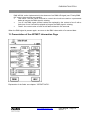
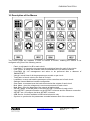
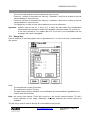
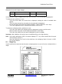
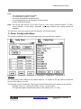
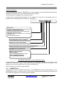
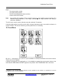
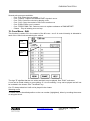
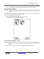
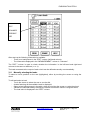
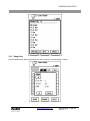
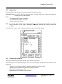
EURODIM TWIN TECH The two CTRL1 and CTRL2 keys are used to display the errors detected by each controller. Indeed, each controller can display different errors, in the CTRL frame in particular. Touch one of the two keys to display the error messages. 39.2 List of Errors displayed in the EURODIM Twin Tech Frame 1 - Displays an error on a mains phase: example: "phase r error". Explanation: the voltage measured at the controller input is outside the operation range. 2 - Displays an error on a cabinet fan that is not functioning: example: "error FAN 1". 39.3 List of Errors displayed in the CTRL Board Frame 1 - “CTRL error”: explanation: there are three processors in each controller. Processor 2 or 3 is not responding. In this case, no dimming will be possible on this controller. 2 - "Comm. error": the controller is not responding to TTD HUMAN INTERFACE (HMI) messages. 3 - “24 V error”: explanation: the 24 V power measurement inside the controller is outside the operation range. 4 - “Temperature error”: explanation: the temperature measured in the controller is not acceptable*. 5 - "9 V error": explanation: the 9 V power measurement inside the controller is outside the operation range. 6 - "Control 9 V error": explanation: the control 9 V power measurement is outside the operation range. 7 - “1V2 error: explanation: the internal 1V2 power measurement is outside the operation range. 8 - "Frequency error": explanation: the mains frequency measured at the controller input is different from the frequency configured in the TTD HUMAN INTERFACE (HMI). 9 - “Software version error”: explanation: the software to be found on the controller (processor 1, processor 2, processor 3) and that in the TTD HUMAN INTERFACE (HMI) Unit are not identical. In all of these cases, only ADB technical personnel can intervene 39.4 List of Errors displayed in the Modules Frame "x module(s) different" The modules actually present in the cabinet are not those used for dimming. Displays the number of different modules detected. Explanation: difference between the reference column and the column present on the CONF. POWER screen. Press the CONF. POWER button that appears next to the error. This provides a shortcut to the CONF. POWER menu. Press the REF.>-PRES button in order to copy the list of modules present in the REFERENCE column "Error on the x, y module(s)” (only for the Sinewave or Thyristor/Fluo modules with fulldiagnostic option) Explanation: Operating error detected on one or more modules. Displays the number of modules where an error has been detected. For more information, press the MOD DIAG button that appears next to the error. This provides a shortcut to the MOD. DIAG. menu of the module of the first circuit experiencing an error. * The maximum ambient temperatures are defined in the EURODIM Twin Tech data sheet. www.adblighting.com User Manual - Page 60 Issue 1.1