1
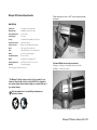
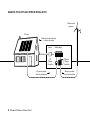
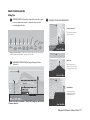
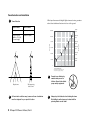
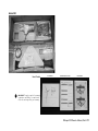
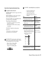
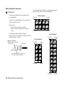
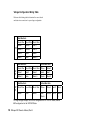
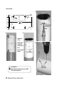
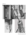
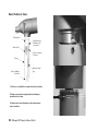
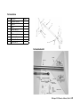
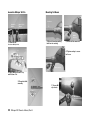
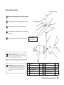
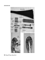
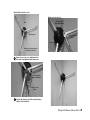
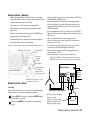
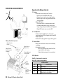
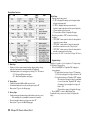
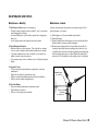
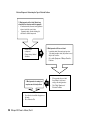
Whisper 200
Owner’s Manual
Installation
Operation
Maintenance
© 2012 Southwest Windpower, Inc.
All Rights Reserved
TABLE OF CONTENTS
SWWP Welcome Letter ............................................................................................................... 3
Safety & Tips.......................................................................................................................................... 4
Whisper 200 Technical Specifications.............................................................................. 5
Example of Off-Grid Installation............................................................................................ 6
PRIOR TO INSTALLATION
Siting Tips................................................................................................................................................. 7
Tower Selection.................................................................................................................................... 8
Arrival Kit................................................................................................................................................... 9
System Wiring....................................................................................................................................... 10
Battery Sizing Tips............................................................................................................................ 11
Battery Configuration and Location ................................................................................. 12
Wind Turbine Electrical Tests....................................................................................................13
INSTALLATION
*For field installation it may be useful to print this section..............14
Setting Wind Turbine Voltage...................................................................................................15-16
Mounting Wind Turbine On Tower.........................................................................................17-20
Tail Installation...................................................................................................................................... 21-22
Blade and Nose Cone Installation....................................................................................... 23-26
Whisper Controller – Mounting.............................................................................................. 27
Whisper Controller – Wiring...................................................................................................... 27-28
Whisper Controller - Circuit Board Switches and Reset Button................ 28-29
OPERATION AND ADJUSTMENTS
Operation of the Whisper Controller.................................................................................... 30
1. Whisper Controller Overview......................................................................................... 30
2. Normal Operation – Whisper Controller.............................................................. 30
3. Diversion Switch...................................................................................................................... 30
4. LED Operation.......................................................................................................................... 30
5. Setting Regulation Voltage (without Display).................................................. 30
6. Whisper Controller Display.............................................................................................. 31
Display Menu Ring Structure.............................................................................................. 31
Display Menu Functions.......................................................................................................... 32
MAINTENANCE AND REPAIR
Maintenance – Monthly.................................................................................................................. 33
Maintenance - Annual...................................................................................................................... 33
Maintenance Log................................................................................................................................. 34
Troubleshooting - Table: Symptoms of Mechanical Problems........................ 35
Troubleshooting - Electrical Diagnosis............................................................................... 36
Troubleshooting - Voltmeter Test............................................................................................37
Troubleshooting - Table: Symptoms of Controller Problems............................ 37
Troubleshooting - Table: Symptoms of Electrical Problems.............................. 38
Whisper 200 Exploded View...................................................................................................... 39
Whisper 200 Exploded View Parts List............................................................................. 40
Whisper Wind Turbine Warranty Agreement.......................................41
Whipser 200 Owners Manual
3-CMLT-1033-02 Revision E
2 Whisper 200 Owner’s Manual, Rev E
Southwest Windpower
Congratulations on your purchase and welcome to our family!
Dear Whisper™ Owner,
Thank you for your purchase of a Whisper wind turbine. We congratulate you on your choice and are confident you will experience years of dependable
service.
Before going any further, please complete and return the enclosed Warranty Registration Card. The conditions of your warranty are dependent upon
the proper installation of Whisper. Furthermore, this will assure you of being kept up-to-date with the latest developments from Southwest Windpower.
These include new options, performance tips, updated software to maximize output and user notices. It is important to know that we do not sell or
distribute your information to any third party. We understand your privacy is important.
Again, welcome to our family and thank you for investing in the future of wind energy with Whisper.
Sincerely,
Southwest Windpower
CE Compliance: The CE marking is a mandatory compliance requirement in EMEA and the UK and although it is self-certification, testing and evidence
support testing is preferred from an independent test house. All Southwest Windpower turbine are third party tested and fullfil all the relevant provisions
of the following directives: Machinery Directive 2006/42/EC, Low Voltage Directive 2004/95/EC, Electromagnetic Compatibility Directive 2004/108/
EC. The report and declaration of conformity are available for inspection on request. The serial number refers to a specific Southwest Windpower
product. This product is considered compliant to CE.
Enter the serial and model number below
Serial Number __________________________________
Model Number __________________________________
Southwest Windpower Inc.
1801 W. Route 66
Flagstaff, AZ 86001 USA
[email protected]
(928) 779-9463
Southwest Windpower GmbH
Mannesmannstr. 6
50996 Cologne
Germany
Tel: +49 (0) 221 16 53 94 50
www.southwestwindpower.eu
Designed in the USA by Southwest Windpower. Manufactured under license by
Luminous Renewable Energy Solutions, India.
Whisper 200 Owner’s Manual, Rev E 3
Important Safety Instructions
Locate your tower well away from occupied buildings and
power lines; a minimum of 76 m (250 ft) is recommended.
Read these instructions in their entirety before installing or
operating.
SAVE THESE INSTRUCTIONS. Enclosed are important instructions that must be followed during installation and maintenance.
Turn Whisper “OFF” and contact Southwest Windpower Technical
Service if unusual noise or operation is observed.
76 m
(250 ft)
High voltage systems present a shock hazard and should be
wired and maintained by a qualified and licensed electrician.
Install Whisper on a calm day - no wind at ground level.
NEVER place objects on top or near the Whisper Controller
enclosure.
In this manual
IMPORTANT: Please take note
TIP: Helpful information
WARNING: Risk of injury or death - proceed with extreme caution
MARINE: Information specific to corrosive environments
4 Whisper 200 Owner’s Manual, Rev E
These devices must dissipate heat as part of
normal operation. FAILURE AND FIRE may
result if airflow is blocked.
Recommended Tools, Equipment and Materials for Installation
Rounded File
Electrical Tape
Ground Rod & Clamp
Electrical Wire and Voltmeter
Wrenches (2) 13mm and 17mm or
Adjustable Wrenches
Torque Wrench (20N-m or 15ft-lb) and
17mm Socket
Electric Drill Motor & 10mm (3/8’’) Metal
Cutting Drill Bit
Sodering Iron and Solder or
Split Bolt Connectors
Leather or Strong Fabric Strap
(secures casting while handling)
Cable Grip/Strain Releif
(support wires inside tower)
Metric Hex Wrench Set
Loctite 242
Center Punch Tool (marks for drilling)
Sawhorses
Pliers
Small Flashlight
Whisper 200 Technical Specifications
WHISPER 200
Turbine casting pivots open to a 45 ° angle creating a potential
pinch point.
Pivot Point
Rated Power
1000 watts at 11.6 m/s (26 mph)
Monthly Energy 200 kWh/mo at 5.4 m/s (12 mph)
Start-Up Wind Speed 3.1 m/s (7 mph)
Rotor Diameter 2.7 m (9 ft)
Voltage
12, 24, 48 VDC*; HV Available at 120v, 230v
Overspeed Protection
Patented side-furling
Turbine Controller
Whisper controller (Optional with all Units)
Mount
6.35 cm pipe (2.5 in schedule 40)
Body
Cast aluminum with corrosion resistant finish
Blades
(3) Carbon reinforced fiberglass
Survival Wind Speed
55 m/s (120 mph)
Weight 30 kg (65 lb) box: 39.46 kg (87 lb)
Shipping Dimensions 1295 x 508 x 330 mm (51 x 20 x 13 in)
Warranty 5 year limited warranty
*Power ratings are normalized for sea level.
Potential
Pinch Point
Rotor Heaviest Part
of Casting
Southwest Windpower strongly recommends:
Straping or securing the casting (as shown below) while
handling so it cannot pivot open.
* The Whisper Controller is factory set for 24-volt operation. If your
system is other than 24 volts, the controller MUST be configured to
your system voltage. Ensure turbine voltage is consistent with rest of
your system voltage.
Note the weight above. Use safe lifting techniques and
protective footwear.
Do not remove strap until casting is secure on tower.
Whisper 200 Owner’s Manual, Rev E 5
EXAMPLE OF AN OFF-GRID HYBRID INSTALLATION
Whisper wind
generator
PV array
Batteries provide electricity
to home via inverter
Inverter
PV
Charge
Controller
PV panels provide
electricity to batteries
6 Whisper 200 Owner’s Manual, Rev E
Battery bank
Whisper
Charge
Controller
Whisper provides
electricity to batteries
1
1
2
2
3
3
PRIOR TO INSTALLATION
Siting Tips
PROPER SITING = Better Performance & Increased Longevity
Look at vegitation deformation to determine best area and
prevailling wind direction.
Prevailing wind
ATYPICAL SITING CONSIDERATIONS
Prevailing wind
Prevailing wind
Prevailing wind
1
2
1
Coastal or Lakeside
3
1
Trees and taller structures
can be down-wind.
1
2
2
3
2
1
2
3
3
3
0
No Deformity
I
II
5-9 mph*
8-11 mph*
wind
Brush & Prevailing
Slight
Slight
Flagging
Flagging
IV
III
V
12-16 mph*
Complete
Flagging
10-13 mph*
Moderate
Flagging
14-18 mph*
Partial Throwing
VI
15-21 mph*
Complete
Throwing
VII
22-higher mph*
Carpeting
1
Griggs-Putnam Index. *Probable mean annual windspeed.
Data prepared by E.W.
Prevailing wind
Prevailingor
wind
Coastal
Lakeside
1
Hewson, J.E. Wade, and R.W. Baker of Oregon State University
1
1
2
2
3
3
2
1
2
EXCESSIVE
TURBULENCE = Fatigue Damage & Shorter
3
Turbine Life
Prevailing
wind
Ridge
Tops
2
3
2
1
3
Ridge Tops
Wind compresses as it
blows over the top of a hill,
increasing the wind speed.
Prevailing wind
1
1
Coastal
Lakeside
Prevailingor
wind
Prevailing wind
1
3
1
2
3
2
Excess
Turbulence
3
3
2
1
Ridge
Tops
Prevailing
wind
3
2
Plateau/Mesa2
1
2
3
Plateau/Mesa
3
Site the generator far
enough from the cliff to
avoid turbulent wind.
76 m (250 ft)
Turbine should be a minimum of 76m (250 ft) away from and 6m (20
ft) above obtacles.
Coastal or Lakeside
Ridge Tops
Prevailing wind
Plateau/Mesa
Prevailing wind
1
2
3
Whisper 200 Owner’s Manual, Rev E 7
Prevailing wind
3
3
2
1
Plateau/Mesa
Tower Selection and Installation
Lattice Towers
Less-expensive
More-expensive
Larger Footprint
(radius is 1/2 - 3/4
of tower height)
Smaller Footprint
Tower height
Guyed Towers
150’ 46m
16 mph
7.3m/s
120’ 37m
15.5 mph
7 m/s
90’ 27m
14.7 mph
6.6 m/s
60’ 18m
13.5 mph
6 m/s
45‘ 14m
12.8 mph
5.7 m/s
33’ 10m
12 mph
5.4 m/s
0
0
20%
41%
75%
100%
124%
Increase in wind power
Calculations based on Power Law Exponenet 0.02
(In area of tall row crops, hedges, a few trees).
Guyed tower
Self-supporting
lattice tower
Soil and wind conditions vary; towers and tower foundations
must be designed for your specific location.
8 Whisper 200 Owner’s Manual, Rev E
Prevent tower climbing by
unauthorized persons or
children. Never climb without
proper safety equipment.
Always stop the blades before climbing the tower.
Both falling from the tower and contact with the
spinning blades can be lethal.
Wind Speed
Wind speed increases with height. Higher towers also raise generators
above the air turbulence that can exist close to the ground.
Tower Selection
Arrival Kit
Generator
Tail Boom
Optional Controller
Blade Extensions
Nosecone &
Hardware Kit
User’s Packet
Tail Fin
User’s Packet
Blades
User’s Manual
5-Year Warranty & Other Docs
Tail Fin Stickers
IMPORTANT: Properly
complete the warranty
registration card; failure to complete and
return the card may affect your warranty.
Whisper 200 Owner’s Manual, Rev E 9
System Wiring
TIP: See the Whisper Controller installation
section for complete wiring details.
Batteries may emit explosive and irritating gas while charging.
Use protective gloves and safety glasses.
Distance = A + B
Never make any electrical connection, light a match or make a spark near
a recently-charged battery.
Controller
B
Turn off all loads, and look away when making a final battery connection.
A
Wire size from wind generator to controller based on voltage configuration and distance (Distance = A + B)
Size
12 V
24 V
48 V
Distance*
Distance*
Distance*
4 mm2 (12 AWG)
—
—
66 m (216 ft)
6 mm2 (10 AWG)
—
—
106 m (346 ft)
10 mm (8 AWG)
—
42 m (138 ft)
168 m (552 ft)
16 mm2 (6 AWG)
—
66 m (218 ft)
266 m (872 ft)
25 mm (4 AWG)
26 m (84 ft)
103 m (339 ft)
414 m (1356 ft)
mm
2
2
2
27 mm (3 AWG)
42 m (136 ft)
165 m (542 ft)
660 m (2168 ft)
34 mm2 (2 AWG)
52 m (170 ft)
208 m (682 ft)
832 m (2728 ft)
42 mm2 (1 AWG)
66 m (216 ft)
262 m (860 ft)
1048 m (3440 ft)
54 mm (0 AWG)
82 m (274 ft)
335 m (1098 ft)
1338 m (4390 ft)
67 mm2 (2/0 AWG)
104 m (342 ft)
416 m (1364 ft)
1662 m (5454 ft)
85 mm (3/0 AWG)
132 m (434 ft)
528 m (1730 ft)
2110 m (6924 ft)
107 mm (4/0 AWG)
166 m (546 ft)
664 m (2177 ft)
2654 m (8710 ft)
2
2
2
2
*If using aluminum wire, multiply the distances in the table by 0.65.
Distances are one way from the turbine connection to Whisper Controller terminals.
10 Whisper 200 Owner’s Manual, Rev E
Simple Tips for Deep Cycle Battery Bank Sizing
In preparation for battery sizing, know:
ELECTRICAL USAGE - the amount of energy consumed 1 day
in Watt-hours (Wh)
DAYS OF AUTONOMY - days of battery back-up required if
unable to charge the batteries by any means.
DEPTH OF DISCHARGE - limit of energy withdrawal to which
you will subject the deep cycle battery bank.
*Deeper discharge = Shortened battery life.
• Recommeded: never discharge a deep cycle battery
below 50% of its capacity.
• Off-grid applications, a 25% DoD will extend battery
life significantly.
TEMPERATURE - Standard for most battery rating is
25 ° C (77 ° F).
Cold temperatures = reduced battery capacity
High temperatures = shortened battery life
RECOMMENDATION - Keep the number of parallel strings of
batteries to three or fewer. More than three strings of batteries,
risks shortening battery life due to uneven charging.
•
•
Batteries in Series = Voltage is Additive
Batteries in Parallel = Ah is Additive
*Example: 2 12V 100Ah Battery Bank
Series 24V 100 Ah
Parallel 12V 200 Ah
CALCULATIONS - calculate battery bank size, use example below:
•
•
•
A system load of 6,000 Watt-hours per day
3 Days of Autonomy (back-up) needed
Planned Depth of Discharge (DoD): 40%
• Battery bank ambient average low 15.6 °C (60 ° F)
• A 48V system
STEPS:
EXAMPLE:
6,000 Wh/day
1.) Identify total daily use in Watt-hours (Wh)
2.) Identify Days of Autonomy (back-up days); multiply
Wh/day by this factor.
3.) Identify Depth of Discharge (DoD) and convert to a
decimal value. Divide result of step 2 by this value.
4.) Select the multiplier corresponding to the lowest
average temperature your batteries will be exposed
to. Multiply result from Step 3 by this factor. *Result
is minimum Wh capacity of battery bank:
Temp in degrees
°C
° F
Factor
26.7 80 +
1.00
21.2
70
1.04
15.6
60
1.11
10
50
1.19
4.4
40
1.30
1.1
30
1.40
-6.7
20
1.59
5.) Divide result from Step 4 by system voltage. Result is
the minimum Amp-hour (Ah) capacity of your battery bank.
3 days of Autonomy:
6,000 x 3 = 18,000 Wh
40%
DoD:
18,000
/ 0.4 = 45,000 Wh
15.6 ° C (60 ° F) = 1.11
45,000 x 1.11 = 49,950 Wh
49,950 / 48 = 1,040 Ah
Whisper 200 Owner’s Manual, Rev E 11
Battery Configuration and Location
Use the diagrams below to determine the series/parallel arrangement for
your system voltage. Please note: based on 6V batteries.
RECOMMENDED:
•
Locate battery in moderately stable room temperature, dry
unoccupied building.
•
If battery is in an occupied building, an enclosure with vent to
outside is required. Follow code.
•
Batter enclosure:
- Allow 5 cm (2 in) on all sides for ventilation.
- Allow 60 cm (2 ft) vertical clearance for maintenace access.
•
To minimize the possibility of EMI (electromagnetic
interference), the line from the battery to the Whisper Controller
should be less than 10 feet (3 m).
Battery Fuse Installation
(Consult local electrical codes)
Battery positive
12 Volt Configuration
To controller
To inverter
To controller
To inverter
48 Volt Configuration
To controller
To inverter
To controller
To inverter
24 Volt Configuration
To controller
To inverter
To controller
To inverter
Nut and bolt
Fuse included (SWWP recommends using
a fuse holder to support wire weight)
12 Whisper 200 Owner’s Manual, Rev E
Wind Turbine Electrical Tests
Complete these tests before mounting blades to rotor. These tests confirm the wind generator is ready to install on the tower.
Ground Test
Open Circuit Test
Check resistance
to ground on any
wire. Resistance
must exceed
10,000 ohms; on many
digital meters this will
show a reading of “OL”.
When the wires are
unconnected the wind
generator rotor
should spin freely.
Short Circuit Test
When all the wires
are shorted together
the alternator should
turn hard.
Phase to Phase Test
When any two wires
are shorted together
the alternator should
turn lumpy as though
there are smooth and
bumpy portions of the
rotor.
Whisper 200 Owner’s Manual, Rev E 13
INSTALLATION SECTION
This section of the manual includes pages 15-29. The pages cover:
Setting Wind Turbine Voltage...................................................................................................15-16
Mounting Wind Turbine On Tower.........................................................................................17-20
Tail Installation...................................................................................................................................... 21-22
Blade and Nose Cone Installation....................................................................................... 23-26
Whisper Controller – Mounting.............................................................................................. 27
Whisper Controller – Wiring...................................................................................................... 27-28
Whisper Controller - Circuit Board Switches and Reset Button................. 28-29
If it is necessary to print installation instructions, these are
the primary pages you will need.
14 Whisper 200 Owner’s Manual, Rev E
INSTALLATION
Set Wind Turbine Voltage
IMPORTANT: The stator wires are coated with varnish that MUST
The Whisper 200 wind turbine and controller must be configured for the
correct system voltage - 12, 24, or 48 volts.
• Whisper controllers are shipped from the factory configured for 24
volt operation.
• The correct turbine voltage is set by altering the 12 stator wire and 3
brush wire connections.
be removed to make a good connection. Remove varnish by
scraping with sharp edge or lightly sandpapering the wire.
• Access wires by removing the “Multi Voltage” cover on the turbine housing.
• The brush wires are interchangeable and not labeled. The brush wires are the larger multistrand wires; 10AWG.
• The stator wires are numbered and color coded with a wire sleeve. For example stator wire
“Red 3” has a red sleeve with the number “3” printed on it. Wire “Red - “ has a red sleeve
with no number. The “-” indicates there is no number.
*Refer to table on next page for specific stator and brush wire connections.
• Cut off the twisted ends of the stator wires and strip off approximately 25 mm (1 inch) of
insulation.
• Hold stripped ends of the wires parallel to each other and twist together clockwise direction
before installing the wire nut.
• Trim wires and twist on the appropriate color wire nut (indicated in the table). Push hard
on the wire nut while twisting clockwise.
• Coat wire nuts and terminal strip connections with dielectric grease to protect wires
against corrosion.
*36V configuration has been removed from this manual. Contact Southwest Windpower technical
support for 36V configuration.
Whisper 200 Owner’s Manual, Rev E 15
Voltage Configuration Wiring Table
Reference the following table to determine the correct brush
and stator wire connections for your voltage configuration.
Red Wire Nuts
12 V
Brush Wire
Brush Wire Brush Wire
White 1
White —
Red 1
White 3
White 2
Red 3
Black 2
Red 2
Black 1
Black —
Red —
Black 3
Red Wire Nuts
Brush Wire
24* White 1
V
White 3
Yellow Wire Nuts
Brush Wire Brush Wire White —
White 2
Red 2
Black 1
Red 3
Red 1
Red —
Black 3
Black —
Black 2
Red Wire Nuts
Yellow Wire Nuts
48* Brush Wire Brush Wire Brush Wire White — White 2 Red 2
V
White 1
Red —
Black 1
Red 1
Black —
White 3
Red 3
Black
2
Black
3
*For high voltage Whisper, use the 24V configuration for a 120V HV Stator, and the
48V configuration for the 240V HV Stator.
16 Whisper 200 Owner’s Manual, Rev E
Mount Turbine On Tower
TIP: Use medium-strength thread locking
compound on all fasteners.
Tower Insert
Tower Insert Kit
For 64 mm insert (2.5 inch Schedule 40 Pipe –2.875 O.D. x .20in Wall)
Check Fit
Engagement hole
64 mm (2.5 inch)
insert
2
Item Description
Qty:
1
Set Screw
(M6 X 20)
2
2
Set Screw M8
X 35
4
3
M8 SS Nylock
Nut
4
Tower
1
3
MARINE: If you are installing your Whisper in a corrosive
environment, use a marinized Whisper and apply Tef-Gel
to all threaded holes to prevent screws from becoming
permanently seized into place.
Whisper 200 Owner’s Manual, Rev E 17
Tower Preparation
3)
CUT 3.
DASHED LINE
4.
.375
9.53 5.
.375
9.53
4.524
114.91
TAB
PLACE TAB
ALIGN WITH TOP OF TOWER
2.5" SCHED 40 PIPE
9.048
229.81
2.500
63.500
Center punch and
mark tower for
drilling.
MARKS SHALL BE ALIGNED
WHEN TEMPLATE IS WRAPPED
AROUND TOWER
2.50" SCHED 40 PIPE
1)
2)
8.00
203.20
DRILL TEMPLATE INSTRUCTIONS:
1.
2.
• Align with top
of tower
DIMENSIONS ARE IN MILLIMETERS, DIMENSIONS IN BRACKETS
3.
CUT OUT TEMPLATE USING DASHED LINE AS SHOWN.
4.
ALIGN TEMPLATE TO TOP OF TOWER AND SECURE IN PLACE.
5.
WITH CENTER PUNCH, MARK 4X HOLE CENTERS ON TOWER.
1.
6.
THIS SHEET SHALL BE PRINTED FULL SCALE, AFTER
PRINTING VERIFY DIMENSION NOTED.
ARE IN INCHES.
TEMPLATE - DRILL
TOWER - WHISPER 100/200
• Wrap template
around tower P/N: 3-CMLT-1051-01
REV C
until
tab arrows
REMOVE TEMPLATE, CHECK DIMENSIONS AND DRILL
4X HOLES.
line up.
• Secure template
with tape
Pipe dimensions
Recommended:
Begin drilling with small bit & work up to 10MM
(3/8”) metal cutting drill bit.
18 Whisper 200 Owner’s Manual, Rev E
4)
Drill center
punch marks
Install Tower Insert
1)
2)
3)
Feed tower insert
onto yaw shaft
Tower Insert
Tower Insert
Yaw Shaft
Alignment
Holes for M8 x
35 Set Screw
5)
4)
M6 x 20
Set Screw
Align hole of tower
insert and yaw
shaft
Slot for Cable
Strain Relief
M6 x 20 Set Screw
Secures Tower Insert
to Yaw Shaft
Whisper 200 Owner’s Manual, Rev E 19
Mount Turbine to Tower
Tower insert
Wires “from”
Support wires by
attaching to the
tower insert
Align holes on
tower insert and
tower
Solder or split bolt
connector
Tower
Wires to Whisper
Controller
Strain relief cable
grip
1) Solder or use split bolts to make electrical connections.
2) Wrap connections thoroughly with electrical tape to
prevent shorts to tower.
3) Support wires to avoid weight on slip ring wires and
wire connections.
20 Whisper 200 Owner’s Manual, Rev E
M8 x 35 Set Screw
(4 Total)
Tower Insert
Flange Resting
on Tower
Tail Installation
Item
Description
Quantity
1
Assembled Generator
1
2
Tail Boom
1
3
Tail Fin
1
4
Hex Bolts, M8 x 55
2
5
Nylon Washer, M8 x 31
2
6
SSTL Washer, M8 x 24
2
7
Nylock Nut, M8
4
8
Hex Bolt, M8 x 25
1
9
Hex Bolt, M8 x 70
1
3
7
2
7
1
5
4
6
9
8
Tail Installation Kit
3.) Tail Fin
2.) Tail Boom
Torque Wrench
13mm Wrench
13mm Socket
7.) M8 Nylock Nut 6.) M8x31 Stainless
steel Washer
9.) M8x70 Hex Bolt
8.) M8x25 Hex Bolt
4.) M8x55 Hex Bolts
5.) M8x31 Nylon Washer
Whisper 200 Owner’s Manual, Rev E 21
Assemble Whisper Tail Fin
Mounting Tail Boom
Tail Boom
M8x24 SS
Washer
M8x31 Nylon
Washer
M8x55 Hex Bolt
1) Attach tail fin.
Not shown: M8 Nylock Nut
M8x70
Hex Bolt
4) Align holes when pushing
tailboom into casting.
5) Secure tail boom anchor.
6) Tighten casting to secure
tail boom.
M8x25 Hex Bolt
2) Apply Whisper sticker to top
and bottom of fin.
3) Complete tailfin
assembly.
7) Secure M8
nylock nuts
Use 13mm or
adjustable wrench
22 Whisper 200 Owner’s Manual, Rev E
Whisper 200 Blade Installation
Leading edge (rounded)
Make sure diversion switch is in the “stop” position.
10
Flat (non-ground) end of blade extension attaches to rotor.
Trailing edge (sharp)
11
7
Ground edge of blade extension face toward blade.
Ground edge
6
Use thread locking compound (Loctite 242 or equivalent)
on all bolts.
9
Torque all bolts to 24 N·m (18 lb-ft). Do not overtighten.
5
1
Paint dot.
See note below.
2
3
IMPORTANT for MARINE units: The enclosed packet of TefGel should be used in threaded holes to prevent corrosion and
screws becoming permanently seized into place.
2
4
3
IMPORTANT: Each turbine blade has a paint dot on the
“front “ of the blade between the blade mounting holes. The
blades should be bolted to the ground end of the blade
extensions so that the paint dot is VISIBLE after the blades
are mounted.
Item Description
Quantity
Item Description
Quantity
1
SS Blade Extension
3
6
Blade
3
2
SS Lock Washer, M10
6
7
SS Nylock Nut M10
6
3
SS Hex Bolt M10 x 40
6
9
SS Flat Washer M10 x 30 (Thick)
3
4
Nose Cone
1
10
SS Shaved Washer M19 x 30
3
5
SS Flat Washer M10 x 20 (Thin)
3
11
SS Hex Bolt M10 x 50
Whisper 200 Owner’s Manual, Rev E 23
BLADE INSTALLATION
6) Whisper 200 Blades
1) Blade Extensions
11) Hex Bolt
M10 x50
3) Hex Bolt
M10 x 40
7) M10
Nylock Nut
10) M10 x 30 Flat
Washer - Shaved
9) M10 x 30 Flat
Washer
5) M10 x 20
Flat Washer
Loctite 242
Torque Wrench
Blade
Extension
M10 x 20
Flat Washer
M10 x 40
Bolt
24 Whisper 200 Owner’s Manual, Rev E
Adjustable
Wrench
17mm
Socket
Rotor
Nose Cone
Attachment
Point
Blade
Extension
to Rotor
Attachment
Point
Attach blade extension to rotor.
Attach nosecone to rotor.
Rotor Plate
M10 x 40 Hex Bolt
M10 x 20 Flat Washer
Rotor
Blade to Rotor Plate
Attachment Point
Blade Extension
Torque to 24 N-m
(18ft-lb)
Nosecone
Ground edge of blade extension
should face toward blade
Ensure nose cone to rotor attachment hole
lines up before tightening blade extensions.
M10 x 40 Hex Bolt
M10 x 20 Flat Washer
Torque to 24 N-m
(18ft-lb)
Any two tip distances should be equal distances
apart to reduce vibration.
Whisper 200 Owner’s Manual, Rev E 25
Attach blades to blade extensions.
M10 x 50 Hex Bolt
M10 x 30 Flat Washer - Shaved
M10 x 50 Hex Bolt
M10 x 30 Flat Washer Not Shaved
Ensure Paint Dot Faces Out
Paint Dot
Torque to 24 N-m
(18ft-lb)
Final Assembly
26 Whisper 200 Owner’s Manual, Rev E
Whisper Controller – Mounting
• When performing preliminary turbine to controller tests, temporarily
mounting the controller close to wind turbine allows easy access while
testing the turbine and controller functionality.
• Perform turbine to controller tests prior to mounting blades.
• Allow effective heat convection by mounting controller vertically
against a wall.
• The dump load side of the controller gets very hot, DO NOT mount
near flammable or heat sensitive materials.
• Controller is NOT rated for outside use and must be protected from
the elements. Mount inside a protected building.
*Controller can be mounted as shown below, or rotated 90 degrees with dump load on top.
Turbine Inputs 12” wire 8” wire
LEDs and diversion
switch
Anemometer
Connection
(optional)
• Setting dip switch voltages before connecting to battery. See “Printed
Circuit Board Switch Settings” section.
• Avoid shorting battery leads together when connecting the battery.
• Connect the battery to the controller. Confirm the microprocessor is
energized by moving the diversion switch to the “stop” position; red
LED should illuminate.
• If not, momentarily depress the “reset” switch on the controller PCB.
• Return the diversion switch to the battery position and observe the red
LED to turn off.
• When connecting the battery do not allow the connection to
power the microprocessor on and off quickly. This could cause the
microprocessor to lock up.
• If the microprocessor locks up and reseting does not correct the
problem, contact Southwest Windpower for instructions.
• After successful startup, cycle red LED by toggling the diversion
switch then switch to “Stop”
• Connect turbine wires to controller (order is not important)
*When the red LED is on, the turbine will not spin as long as at least two of its wires are connected, except in strong winds.
Battery Outputs
Earth Ground located
inside controller
between turbine &
battery mounting blocks
Dump Load Side/Hot Side
Whisper Controller
Optional
Anemometer
NRG #40
Ground
Lug
Conduit Knockouts (on bottom of controller)
accommodates .75”, 1.25” & 1.5
Whisper Controller – Wiring
Fuse
Connecting
Remove the Controller electronic cover and connect the battery, turbine
and ground wires as shown in the accompanying schematic.
Controller MUST be connected to the batteries BEFORE making
the wind turbine connections.
Correct polarity MUST be observed when connecting battery
cables.
Included
Wire size for wiring to the battery
(3 meters each way):
12V system: 1/0 gauge or larger
24V system: 2 gauge or larger
48V system: 6 gauge or larger
Battery Bank
Whisper 200 Owner’s Manual, Rev E 27
Dump Load Wiring
• Wire the resistive “dump” load for the correct system voltage
• Sufficient jumper wires are provided to achieve any system voltage
configuration
8” wire
Whisper Controller - Printed Circuit Board Switches and
Reset Button
Switches for
setting system
voltage
Potentiometer
24 Volt
Systems
12 Volt Systems
12” wire
48 Volt Systems
12” wire
12” wire
Optional Anemometer Connection
• Whisper Controller is designed to accomodate a model #40 NRG
anemometer (www.nrgsystems.com; Item Number 1900).
• Connect anemometer wires to labeled PCB terminal block.
• Anemometers require specific polarity; observe the labeling on the
terminal block connections.
• If applicable, connect a grounding shield to the controller’s grounding
terminal.
• Mount anemometer close to turbine without entering the turbine’s
swept area (see manufacturer’s installation instructions).
Understanding Voltage Regulation:
“Regulation-On”
• Controller is regulating battery voltage and diverting power to the
dump load
• If the controller measures battery voltage above “regulation-on
voltage” for more than 30-40 seconds, it begins diverting power
“Regulation-Off”
• Controller resumes battery charging
• If the controller measures battery voltage below “regulation-on
voltage” for more than 30-40 seconds, it stops diverting power and
begins battery charging
28 Whisper 200 Owner’s Manual, Rev E
Reset switch
• Six switches on the PCB are used to set operating system
parameters.
• The default settings are suitable for most systems installations and
should only be changed to alter system voltage.
Reset Switch:
• Whisper Controller operation is controlled by a microprocessor.
• The PCB reset switch resets the microprocessor. Depressing the
reset switch has the same effect as disconnecting a battery cable.
• To reset momentarily press the reset button. If it is necessary to
depress a second time, wait approximately 15 seconds.
• Voltage regulation points set using the optional display setting
will be lost if reset switch is depressed or a battery cable is
disconnected; controller will revert to potentiometer set points.
Printed Circuit Board Switch Settings
Switches 1 and 2, System Voltage
Select the correct system voltage by setting the position of switches 1
and 2 according to the following table.
System Voltage
Switch 1
Switch 2
12 Volt
ON
ON
24 Volt
OFF
ON
48 Volt
OFF
OFF
Switch 4, Voltage Hysteresis, Default Setting “OFF”
OFF
Controller starts or stops charging at the voltage regulation
points set through optional display or by the PCB potentiometer
ON
Voltage regulation-on point (battery stops charging) set using
potentiometer increases by:
- 1.0 volts for 12V systems
- 2.0 volts for 24V systems
- 4.0 volts for 48V systems
Votage regulation-off point (battery charging resumes) is
not affected
Voltage hysteresis switch does not increase the regulation on
and off set points using the optional display
After changing the system voltage depress the reset switch to “read and
save” the new voltage setting.
Switch 5, Potentiometer Enable, Default Setting “OFF”
Switch 3 , Time Hysteresis, Default Setting “ON”
ON
30-40 second delay for controller to start or stop charging when
regulation set point is reached
OFF
No-delay – charging will stop or start immediately when
regulation set point is reached
It is not necessary to depress the Reset Switch after changing the switch setting.
*Southwest Windpower STRONGLY recommends Switch 3 remain in
ON position
ON
Enables reading potentiometer voltage in real time. Resolution
limits are:
- 0.2 volts for 12V systems
- 0.4 volts for 24V systems
- 0.8 volts for 48V systems
Voltage regulation points must be set using potentiometer not
optional display
OFF
Prevents changing the voltage regulation point using the
potentiometer
It is not necessary to Reset after changing the switch 4 & 5 settings.
Before adjusting the Voltage Regulation-On set-point understand that
increasing the voltage will not increase the turbine’s output voltage or
current. This set-point only adjusts the “shut-down” voltage for battery charging.
Overcharging will significantly reduce a battery’s life expectancy.
Switch 6, Default Setting “OFF”
There is no function presently associated with this switch. SWWP
recommends leaving the switch in the OFF position.
Whisper 200 Owner’s Manual, Rev E 29
OPERATION AND ADJUSTMENTS
Operation of the Whisper Controller
Turbine
Battery
Remote
Dispaly
2) Normal Operation
– Interface mechanisms: LED, diversion switch, voltage regulation adjustment, PCB configuration switches and LCD display (if equipped)
– Interface allows setting regulation voltage, monitoring system Whisper Contoller
with display
Whisper Controller Components
Whisper Controller
Display
Whisper Controller
Resistive Load bank
(Dumpload)
Whisper Controller
Electronic Cover
Diversion Switch and
LED’s (Far Side)
Whisper
Controller
Electronics
Whisper Controller
Regulation
Potentiometer
30 Whisper 200 Owner’s Manual, Rev E
1) Overview
— Controls and converts turbine power. Functions:
- Rectifies power from wild AC to DC voltage
- Contains diversion load & controls voltage regulation
- Monitors voltage, current, energy production and wind speed (if equipped)
– Optional LCD Display:
- Offers instant access to operational parameters and performance measurements; voltage, current, power,
energy, charge, peak power and wind speed (if equipped)
- Display LEDs function same as controller LED
3) Diversion Switch
– Diverts power from batteries to dump load to avoid battery overcharging
– Considerations if activated:
- Will not stop a spinning turbine but will not allow a stopped turbine to start spinning
- If turbine blades are spinning, it is normal and safe
4) LED Operation
Red LED = Power diverted to dump load;
Green LED = Turbine is charging battery
LED INDICATORS
RED
GREEN
OFF
ON
Battery charging
INTERPRETATION
BLINKING
OFF
Power to diversion load to regulate battery voltage
ON
OFF
Power to diversion load by operator request (via
Diversion Switch or remote Display).
5) Setting Regulation Voltage (without Display) *See page 22 - Switch 5
• Turning the potentiometer clockwise (CW) increases the voltage set
points. Use following chart for approximate potentiometer set points.
Note: Determine the initial potentiometer position by turning fully
counter clockwise (CCW). Count and record the number of turns.
Pot Position
Regulation Off Voltage
Regulation On Voltage
Fully CCW
12.0V 24.0v 36.0v 48.0v
13.0V 26.0v 39.0v 52.0v
1/4 Turns CCW
13.0V 26.0v 39.0v 52.0v
14.0V 28.0v 42.0v 56.0v
Factory Preset
13.4V 26.8v 40.2v 53.6v
14.4V 28.8v 43.2v 57.6v
1/2 Turns CW
14.0V 28.0v 42.0v 56.0v
15.0V 30.0v 45.0v 60.0v
3/4 Turns CW
14.0V 28.0v 42.0v 56.0v
16.0V 32.0v 48.0v 64.0v
Fully CW (18 turns)
14.0V 28.0v 42.0v 56.0v
17.0V 34.0v 51.0v 68.0v
• Verify display function: text should appear on LCD display after
display and batteries are connected to controller.
• It may be necessary to adjust LCD contrast:
- Locate small hole between buttons and LEDs
- Insert small screwdriver through display cover
- Turn clockwise to lighten
- Turn counter-clockwise to darken
• If text is still not visible, disconnect & reconnect cable to display to
reset.
Display Menu Ring Structure
6.) Whisper Controller Display (Optional)
“B” Menu
Function Button
LCD Display
Screen
“A” Menu
Function Button
Green LED
LCD Contrast
Adjustment
Red LED
• Designed to mount on:
– Whisper controller base unit (a short CAT5 Ethernet cable is provided) or 4” wall type switch receptacle
• If mounted on controller, connect CAT5 to jack closest to diversion
switch to disable controller LED
• Mounting on Whisper Controller
– Remove electronics cover
– Remove sheet metal insert where display will mount
– Use hardware provided to mount display to electronics cover
– Hardware: 8-32 x 3/8” black oxide SS screws and 8-32 nuts
with captive star washers
• If mounted remotely, the display can be mounted up to 300 m (1,000
ft) from controller; longer CAT5 cable must be purchased by user.
Whisper 200 Owner’s Manual, Rev E 31
Display Menu Functions
4) Mode Page
• Displays current charge mode
– If “ON” is displayed the battery can be charged; turbine will spin in adequate wind
– If “OFF” is displayed turbine power produced is
diverted to dump load; turbine will not spin in light winds – “A” menu button toggles the mode
– “B” menu button returns to Regulation Set page
• Controller can switch to “OFF” mode in the following
conditions”
– “OFF_REM” - turbine power is diverted to dump load via request from remote display
– “OFF_MAN” - turbine power is diverted to dump load when diversion switch is moved to “Stop” position
– “OFF_REG” - turbine power is diverted to dump load via automatc regulation at present voltage
*Diversion switch set to “OFF” overrides Remote Display “ON” function
1) Main Page
• Displays controller’s measurements: battery charging status, voltage,
and current and turbine power and windspeed (if equipped)
• Main display leads to four sub-pages by selecting “A” or “B” functions
– “A” – Energy and History menu pages
– “B” – Mode and Regulation menu pages
2)
•
•
•
Energy Page Displays accumulated kWh and kAh since last reset
Accumulated data can be reset by selecting menu option “B”
Menu option “A” goes to the History page
3)
•
•
•
History Page
Displays average and peak windspeed and turbine power since reset
Note: windspeed is only available if anemometer is installed
Reset accumulation data by selecting menu option “B”
Menu option “A” goes to the Main Display page
32 Whisper 200 Owner’s Manual, Rev E
5) Regulation Page
Digitally set “regulation on” and “regulation off” voltages using
the Regulation Setpage Menu
• Select “A: CHANGE” for “Regulation ON” subpage for
voltage changes
– “B” menu button increases voltage to 17V maximum. At 17V, if pressed again, the voltage rolls back to 13V
– “A” menu button brings up “Regulation OFF” subpage
- “B” menu button increases voltage to a maximum of one volt lower than “Regulation ON” voltage. At maximum, if pressed again, the voltage rolls back to 12V
- “A” menu button returns to Regulation Set page
• Select “B:SKIP” to return to Main Display Page
*Regulation Off voltage cannot be specified above Regulation On
voltage
MAINTENANCE AND REPAIR
Maintenance – Monthly
Maintenance - Annual
1) Test Diversion Control (check electrical wiring)
• Divert the load by setting the diversion switch to “stop” in a moderate
wind (charging but not furling)
• No unusual difficulty or noise should be experienced in stopping the
blade rotor
• A noise during diversion can indicate a disconnected wire
Lower the tower and give wind generator a complete inspection. Fix or
replace any warn or loose parts.
2) Check Mechanical Condition
• Watch and listen from the tower base. There should be no mechanical noise, rattle or vibration and the blades and tail must not wobble
• If you hear mechanical noise, rattle or vibration, or see blade or tail
wobble, lower the tower for inspection
• If you experience any of these conditions, refer to Troubleshooting and
Repair
3) Inspect the Tower
• Follow all inspection and maintenance requirements of the tower
manufacturer
• Tighten all nuts and bolts, especially wire clips
• Check for cracks and bent/broken parts at the anchors and base
• Check for broken strands and tighten wires
4) Check the Battery
• Consult your battery manufacturer maintenance guide
• Tighten battery connections
• Remove corrosion and protect terminals
a) Check tightness of all tower and blade nuts and bolts
b) Check all bearings
c) Clean the blades with a mild detergent to remove all dirt and debris.
Replace blades if they are cracked or damaged
d) Check the pivot bushing and bore. Lay the turbine down while it is
completely unfurled (the normal operating position), and see if you
can wobble the lower half. If it wobbles significantly (noticeable play),
then the bushing and/or bore is ovalized. Replace the bushing first
and retest it. If it still wobbles then the castings need to be replaced.
Do not tighten
pivot pin nut.
Tighten tower
and blade
mounting bolts.
Whisper 200 Owner’s Manual, Rev E 33
Maintenance Log
Observe monthly and annual inspection requirements. Record all maintenance and repair work.
Date
Problem/Observation
34 Whisper 200 Owner’s Manual, Rev E
Action Taken
Troubleshooting and Repair
Table: Symptoms of Mechanical Problems
Symptom
Blade rotor is stationary, even in high winds
Probable Cause
Correction
a) Ice in generator, or on blades
a) Wait for warm weather. Leave running unless
vibration is substantial
b) Turn blades gently by hand and use thin
material to dislodge debris
c) Remove rotor and re-glue magnets – contact
factory/ dealer/ distributor
d) Contact factory or distributor
b) Debris between rotor and stator
c) Loose, broken or rubbing magnet
d) Bad or worn bearing
Blade rotor will not turn at all except in high wind,
scraping or rubbing sound at low rpm, always
stops at same blade position
a) Same as above, except more likely to be
high magnet or bad bearing.
a) Same as above
Blade rotor is hard to start, output is lower & there
is more blade noise than usual; appears out of
balance.
a) Ice on blades
d) Blade(s) on backwards
a) Wait for warm weather. Leave running unless
vibration is substantial
b) Clean with mild detergent
c) Replace damaged blade – contact factory/
dealer/ distributor
d) See blade installation
Blade rotor turns slowly, never spins rapidly
a) Blades on backwards.
a) See blade installation
Tail, generator and tower vibrate or shake
excessively at all or some wind speeds
a) Blade out of balance
a) Replace blade – contact factory/ dealer/
distributor
b) Contact factory/ dealer/ distributor
c) Contact factory/ dealer/ distributor
d) Perform phase-to-phase testing
SAFETY FIRST - shut down turbine until a
physical inspection can be performed.
Rattle or clunking from generator
SAFETY FIRST - shut down turbine until a
physical inspection can be performed.
b) Dirty blades
c) Damaged blade(s)
b) Blade not tracking
c) Rotor out of balance
d) Shorted alternator or wiring
a) Generator loose in tower. Rotor loose on
shaft, loose tail, missing rubber bumper,
wires slapping inside of mast, governor
pivot bolt loose
b) Worn bearings
c) Shaft broken
a) Inspect for damage and repair as required
Retighten mounting hardware, use Loctite or
equivalent thread-locking compound.
b) Replace bearings – contact factory/ dealer/
distributor
c) Replace shaft – contact factory/ dealer/
distributor
Whisper 200 Owner’s Manual, Rev E 35
Electrical Diagnosis - Determining the Type of Electrical Problem
1. Wind generator will not start (blades turn
slowly as if the diversion switch is engaged):
• In moderate wind, disconnect wind generator
wires at controller one at a time.
• If generator starts, the wire allowing it to
start lead to a failed component.
•
•
Replace failed
component
Contact factory/ dealer/
distributor
OR
2. Wind generator still does not start:
• In moderate wind, disconnect any two wires.
• If the wind generator starts, the problem is most
likely in the controller.
• Go to table: Symptoms of Whisper Controller
Problems
•
3. Wind generator is running, but
may have an electrical problem.
•
•
Use voltmeter to read the voltage across
the leads
Go to Voltmeter Test
36 Whisper 200 Owner’s Manual, Rev E
OR
•
If the generator does not start
the problem is in the tower
wiring or the wind generator.
Go to Table: Symptoms of
Electrical Problems.
Voltmeter Test
Test
What it tells you
1. Voltage increases and decreases slowly relative •
to wind speed across all combinations of
paired wires
Everything is OK.
2. No voltage across one set of two wires
•
One wire from the wind generator is not carrying power. Check the tower wiring and
controller connections to ensure proper wiring.
If the wiring is correct contact authorized factory/ dealer/ distributor for further assistance.
•
Possibly a shorted diode. Contact factory/ dealer/ distributor.
3. Voltage significantly higher across one set of
two wires than the others
•
4. Voltage significantly lower across one set of
• There is a bad connection at wind turbine voltage connections or faulty stator winding.
two wires than the others
Contact factory/ dealer/ distributor.
Should these results appear inconclusive in determining the problem proceed directly to Table: Symptoms of Electrical Problems or see Table: Symptoms of Whisper Controller Problems below.
Table: Symptoms of Whisper Controller Problems
Symptom
Probable Cause
Blade rotor turns slowly, even in strong wind
a) Brake switch ON
b) Shorted diode
c) Dead or disconnected battery
d) Short in wiring to turbine
a) Move switch to “OFF”
b) Contact factory/ dealer/ distributor
c) Ensure battery voltage at controller terminals
is at least 10v, 20v, 32v, or 44v depending
on turbine model
d) See Table of Electrical Problems
Doesn’t regulate, red LED off and dump load
is cold
a) Battery volts below setting
b) Bad circuit board
a) Check battery with voltmeter (see Voltmeter
Test). Adjust voltage setting
b) Contact factory/ dealer/ distributor
Doesn’t regulate, red LED on and dump load
is cold
a) Dump load burned out, disconnected or
wired incorrectly
b) Bad connection from circuit board to
power block
a) Contact factory/ dealer/ distributor
a) Wrong battery voltage setting
a) Check battery with voltmeter (see Voltmeter
Test) Adjust voltage setting
b) Contact factory/ dealer/ distributor
c) Move diverson switch to “Start”. Check and
restore connection, if needed
Dumpload always on, red LED on
b) Bad circuit board
c) Diversion switch set to “Stop” or
disconnected
Correction
b) Contact factory/ dealer/ distributor
Whisper 200 Owner’s Manual, Rev E 37
Table: Symptoms of Electrical Problems
Symptom
Probable Cause
Blade rotor will not turn or turns slowly, even in
high wind
a) Diversion switch is ON.
b) Battery is dead (voltage less than 1/2
nominal)
c) Incorrect turbine wiring.
d) Short circuit in wiring from generator to
controller
e) Failed component in controller
f) Short circuit in brush card or slip ring
assembly
g) Short circut in turbine
a) Turn Diversion switch to Battery position
b) Disconnect load and /or battery from
generator until it starts; charge battery
c) Rewire
d) Check wiring from generator to controller
a) Two or three wires open between turbine
and controller
b) Controller diodes open or wire is
disconnected at diode terminal
c) Battery voltage over 50%
a) See Voltmeter Test
Blade rotor runs too fast, may whistle; no output,
no unusual mechanical noise
d) Turbine may be in regulation, but wind is
too high for turbine to stop
e) Load or battery disconnected
Correction
e) See Voltmeter Test
f) Contact factory/ dealer/ distributor
g) Contact factory/ dealer/ distributor
b) See Voltmeter Test
c) Examine battery specifications and
regulation set point. Replace improperly
sized battery if necessary
d) Wait for calmer conditions. Engage diversion
switch to determine proper operation
e) Check all connections
Blade rotor runs too fast, may whistle, output less
than 50% for wind speed, growling , buzzing or
vibration felt by hand or mast
a) Disconnect wire between turbine and
controller
b) One open or disconnect diode
c) One slip ring or brush not making good
contact
a) See Voltmeter Test
Blade rotor runs too slowly, low output, no
unusual mechanical noise
a) Battery voltage low or dead battery
b) Incorrect turbine wiring
a) Disconnect loads and let battery charge
b) Check turbine wiring connections or rewire
Green charge light comes on momentarily during
wind gusts or only comes on in very high wind
conditions
a) The turbine and controller voltage
settings may be set to different voltage
configurations
a) Verify the turbine output wiring, the diversion
load and the controller DIP switch are
configured to the same voltage
38 Whisper 200 Owner’s Manual, Rev E
b) See Voltmeter Test
c) Contact factory/ dealer/ distributor
Whisper 200 Exploded View
Mechanical Repairs and Parts Replacement
• Use exploded view and parts list as guide for replacement parts and
troubleshooting.
• Southwest Windpower strongly recommends internal turbine
repairs be performed by an authorized service dealer or
Southwest Windpower.
• Unauthorized repairs leading to turbine damage may void the
warranty.
25
24
1
28
2
35
4
5
6
15
2
37
29
32
36
33
34
8
14
17
18
19
16
20
12
9
10
11
3
7
13
22
21
Part descriptions on next page
23
31
30
24
25
26
38
27
Do not attempt repairs on top of the
tower. Perform repairs only after tower
has been lowered.
Whisper 200 Owner’s Manual, Rev E 39
Whisper 200 Exploded View Parts List
No.
Description
Qty.
Part No.
No.
1
Casting-Upper-Machined-100/200-Land
Casting-Upper-Machined-100/200-Marine
1
3-CMBP-1225-02
3-CMBP-1225-04
2
Nylock Nut, M8
1
3-HDNT-201-02
3
Hex Head Cap Screw M8 x25
1
3-HDBT-2004-69
4
Stator-200-Land-LV
Stator-200-Marine-LV
Stator-200-Land-HV
Stator-200-Marine-HV
1
3-CMBP-1199-01
3-CMBP-1199-02
3-CMBP-1199-03
3-CMBP-1199-04
5
Snap Ring-20mm-Zinc
1
3-CAOT-1064
6
Bearing-6204-Sealed
Bearing-6204-Shielded
2
2
3-CABR-1003
3-CABR-1007
7
Spindle-100/200
1
3-CMBP-1139
8
Snap Ring-49mm-Zinc
1
3-CAOT-1066
9
Rotor-200
1
3-CMBP-1128-02
10
Washer M6, SS
6
3-HDWA-200-07
11
Socket Head M6 x 16
6
3-HDBT-2000-035
12
Stop Bumper
1
3-CMBP-1177
13
Stop Bumper
1
3-CMBP-1177
14
Screw-PPH-M5 x 60
4
3-HDBT-2001-027
15
Bushing-Bronze
1
3-CAOT-1052
16
Pivot Shaft-100/200
1
3-CMBP-1122
17
Cover-Brush Card
1
3-CMBP-1055
18
Brush Card Holder
1
3-CMBP-1056
19
Brush-Spring 1”
3
3-CAOT-1050
20
Brush-Transmission-No Sonic Weld
2
3-CMBP-1054-05
21
Brush-Ground
1
3-CMBP-1054-02
22
Ground Screw M5 x 10
1
3-HDBT-2001-017
23
Casting-Lower-Machined-100/200-Land
Casting-Lower-Machined-100/200-Marine
1
3-CMBP-1226-02
3-CMBP-1226-04
24
Washer, M8 x 16
1
3-HDWA-102-10
25
Nylock Nut, M10
2
3-HDNT-201-03
26
Yaw Shaft Assembly-100/200
1
3-CMBP-1194
40 Whisper 200 Owner’s Manual, Rev E
Description
Qty.
Part No.
27
Snap Ring-69mm-Zinc
1
3-CAOT-1067
28
Washer-Bronze-1” x 1-1/2” x 1/16”
3
3-HDWA-904
29
Hex Bolt, M8 x 25 SS
1
3-HDNT-2004-069
30
Hex Bolt, M8 x 70 SS
1
3-HDBT-2006-077
31
Tail Boom-200
1
3-CMBP-1181
32
Washer-Flat-Nylon-1.235” x .365” x 1.1”
2
3-HDWA-905
33
Washer-Flat-Metric-SS-A2-M8 x 24
2
3-HDWA-201-09
34
Washer-Nylon-#10
1
3-HDWA-920
35
Screw-HHCS-M8 x 55-SS-A2
2
3-HDBT-2006-074
36
Tail Fin-200
1
3-CMBP-1143
37
Bearing-6206-Sealed
2
3-CABR-1004
Whisper Wind Turbine Warranty Agreement
Hardware Warranty
Southwest Windpower, Inc., (“Southwest Windpower”) will repair or replace free of charge any part
or parts of the Southwest Windpower Whisper™ Wind Turbine determined by Southwest Windpower
to be defective in materials and/or workmanship under normal authorized use consistent with
product instructions for a period of five years from the date the original purchaser (“Customer”)
receives the Wind Turbine (“Start Date”). This warranty extends only to the original purchaser. The
Customer’s sole and exclusive remedy and the entire liability of Southwest Windpower, its suppliers and affiliates under the warranty is, at Southwest Windpower’s option, either (i) to replace the
Wind Turbine with new or reconditioned Wind Turbine, (ii) to correct the reported problem, or (iii)
to refund the purchase price of the Wind Turbine. Repaired or replaced products are warranted for
the remainder of the original warranty period.
Restrictions
Problems with the Wind Turbine Products can be due to improper use, lack of maintenance,
non-Southwest Windpower additions or modifications or other problems not due to defects in
Southwest Windpower’s workmanship or materials. No warranty will apply if the Wind Turbine (i)
has been altered or modified except by Southwest Windpower, (ii) has not been installed, operated,
repaired, or maintained in accordance with instructions supplied by Southwest Windpower, (iii) has
been exposed to winds exceeding 120 mph (54 m/s), (iv) or has been subjected to abnormal
physical, thermal or electrical stress, misuse, negligence, or accident. If Southwest Windpower’s
repair facility determines that the problem with the Wind Turbine is not due to a defect in Southwest
Windpower’s workmanship or materials, then the party requesting warranty service will be responsible for the costs of all necessary repairs and expenses incurred by Southwest Windpower.
Warranty Claims & Return Procedures
In order to be eligible for service under this warranty the Customer MUST return the warranty
registration card included with this Warranty Agreement within 60 days of purchasing the Wind
Turbine. Additionally, the Customer must submit a service request for Wind Turbine covered by this
warranty within the warranty period by contacting Southwest Windpower in writing or via telephone
and obtaining a Return Authorization (“RA”) number. This RA must be obtained before returning
any product under this warranty.
Notification must include a description of the alleged defect, the manner in which the Wind Turbine
was used, the serial number, and the original purchase date in addition to the name, address, and
telephone number of the party requesting warranty service. Within 3 business days of the date of
notification, Southwest Windpower will provide the Customer with a RA number and the location to
which the Customer must return the defective Wind Turbine. Any Wind Turbine requiring warranty
repair shall be transported at the expense and risk of the party requiring warranty service, including but not limited to proper packaging of the Product. The Customer must return the entire Wind
Turbine kit within 30 days after issuance of the RA number. Southwest Windpower will be under no
obligation to accept any returned Wind Turbine that does not have a valid RA number. Customer’s
failure to return the Wind Turbine within 60 days of its receipt of a RA number may result in
cancellation of the RA. All parts that Southwest Windpower replaces shall become Southwest
Windpower’s property on the date Southwest Windpower ships the repaired Wind Turbine or part
back to the Customer. Southwest Windpower will use all reasonable efforts within five days of
receipt of the defective Wind Turbine to repair or replace such Wind Turbine. If a warranty claim
is invalid for any reason, the Customer will be charged at Southwest Windpower’s then-current
rates for services performed and will be charged for all necessary repairs and expense incurred by
Southwest Windpower.
Disclaimer
EXCEPT FOR THE EXPRESSED WARRANTY SET FORTH ABOVE, SOUTHWEST WINDPOWER
DISCLAIMS ALL OTHER EXPRESSED AND IMPLIED WARRANTIES, INCLUDING THE
IMPLIED WARRANTIES OF FITNESS FOR A PARTICULAR PURPOSE, MERCHANTABILITY
AND NON-INFRINGEMENT. NO OTHER WARRANTY, EXPRESSED OR IMPLIED, WHETHER
OR NOT SIMILAR IN NATURE TO ANY OTHER WARRANTY PROVIDED HEREIN, SHALL
EXIST WITH RESPECT TO THE PRODUCT SOLD UNDER THE PROVISIONS OF THESE
TERMS AND CONDITIONS. SOUTHWEST WINDPOWER EXPRESSLY DISCLAIMS ALL
LIABILITY FOR BODILY INJURIES OR DEATH THAT MAY OCCUR, DIRECTLY OR INDIRECTLY,
BY USE OF THE PRODUCT BY ANY PERSON. ALL OTHER WARRANTIES ARE EXPRESSLY
WAIVED BY THE CUSTOMER.
Limitation of Liability
UNDER NO CIRCUMSTANCES WILL SOUTHWEST WINDPOWER OR ITS AFFILIATES OR
SUPPLIERS BE LIABLE OR RESPONSIBLE FOR ANY LOSS OF USE, INTERRUPTION
OF BUSINESS, LOST PROFITS, LOST DATA, OR INDIRECT, SPECIAL, INCIDENTAL, OR
CONSEQUENTIAL DAMAGES, OF ANY KIND REGARDLESS OF THE FORM OF ACTION,
WHETHER IN CONTRACT, TORT (INCLUDING NEGLIGENCE), STRICT LIABILITY OR
OTHERWISE, RESULTING FROM THE DEFECT, REPAIR, REPLACEMENT, SHIPMENT OR
OTHERWISE, EVEN IF SOUTHWEST WINDPOWER OR ITS AFFILIATE OR SUPPLIER HAS
BEEN ADVISED OF THE POSSIBILITY OF SUCH DAMAGE. (Note: some states and provinces
do not allow the exclusion or limitation of incidental or consequential damages, so these limitations
may not apply to you). Neither Southwest Windpower nor its affiliates or suppliers will be held liable
or responsible for any damage or loss to any items or products connected to, powered by or otherwise attached to the Hardware. The total cumulative liability to Customer, from all causes of action
and all theories of liability, will be limited to and will not exceed the purchase price of the Product
paid by Customer. This Warranty gives the Customer specific legal rights and the Customer may
also have other legal rights that vary from state to state or province to province.
Whisper 200 Owner’s Manual, Rev E 41
Southwest Windpower Inc.
1801 West Route 66
Flagstaff, Arizona 86001 USA
t: +1 928.779.9463
f: +1 928.779.1485
Southwest Windpower GmbH
Mannesmannstr. 6
50996 Cologne Germany
t: +49 (0) 221 16 53 94 50
www.windenergy.com
42 Whisper 200 Owner’s Manual, Rev E