1
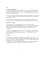
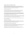
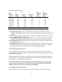
利佳興業股份有限公司
RICH ELECTRIC CO.,LTD.
INVERTEK®
SUNSTAR SERIES
SOLAR CHARGE CONTROLLER
SS-30C/ SS-45C/ SS-60C
Installation and Operation Manual
USER MANUAL
Solar Battery Charging
Load Control
Diversion Charge Control
CONTENTS
Specifications ..................................................................................................................................I
Chapter 1 SunStar Description................................................................................................. 1-1
1.1 Versions and Ratings ....................................................................................... 1-1
1.2 Operating Modes.............................................................................................. 1-2
1.3 Adjustability ..................................................................................................... 1-2
1.4 General Use....................................................................................................... 1-3
1.5 Optonal Available ............................................................................................ 1-4
Chapter 2 SunStar Installation................................................................................................. 2-1
2.1 General Information........................................................................................ 2-1
2.2 Installation Overview....................................................................................... 2-1
2.3 Control Terminal Connection......................................................................... 2-2
2.4 Installation Steps.............................................................................................. 2-4
2.4.1 Mounting ................................................................................................ 2-5
2.4.2 Solar Battery Charging DIP Switch Settings ....................................... 2-5
2.4.3 Load Control DIP Switch Setting.......................................................... 2-8
2.4.4 Diversion Charge Control DIP Switch Settings ................................... 2-11
2.4.5 Battery Temperature Sensor (BTS) ...................................................... 2-11
2.4.6 System Wiring and Power-Up ............................................................... 2-11
2.4.7 Finish Installation ................................................................................... 2-13
2.5 Communication with CombiPlus/SuperCombi............................................. 2-14
Chapter 3 Front Cover of SunStar Operation ........................................................................ 3-1
3.1 LED Status Indicator....................................................................................... 3-2
3.2 Charge Control or Diversion Control Mode Indicatons .............................. 3-2
3.3 Load Control Indications ................................................................................ 3-2
3.4 Equalization Mode Indication ........................................................................ 3-3
3.5 Fault Mode Indication ..................................................................................... 3-3
3.6 LCD Meter Displays ........................................................................................ 3-4
3.6.1 LCD Displays Flow ................................................................................. 3-5
3.6.2 Fault Messages ........................................................................................ 3-6
Chapter 4 Solar Battery Charging ........................................................................................... 4-1
4.1 PWM Battery Charging .................................................................................. 4-1
4.1.1 Four Stages of Solar Charging............................................................... 4-1
4.1.2 Battery Charging Notes.......................................................................... 4-1
4.2 Standard Battery Charging Programs........................................................... 4-2
4.3 Temperature Effects ........................................................................................ 4-3
4.3.1 Battery Temperature Sensor (BTS) ...................................................... 4-3
4.4 Equalization...................................................................................................... 4-4
4.4.1 Standard Equalization Programs.......................................................... 4-5
4.4.2 Typical Equalization............................................................................... 4-6
4.4.3 When to Equalize .................................................................................... 4-6
4.5 Float................................................................................................................... 4-6
Chapter 5 Load Control ............................................................................................................ 5-1
5.1 Load Control Settings...................................................................................... 5-1
5.2 Inductive Loads (Motors)................................................................................ 5-1
5.3 General Load Control Notes ........................................................................... 5-2
5.3.1 Inverters................................................................................................... 5-2
5.3.2 Parallel SunStar ...................................................................................... 5-2
5.3.3 Reverse Polarity ...................................................................................... 5-2
Chapter 6 Diverson Charge Control ........................................................................................ 6-1
6.1 Diversion Charge Control ............................................................................... 6-1
6.2 Diversion Current Ratings .............................................................................. 6-1
6.3 Stanadrd Diversion Battery Charging Programs ......................................... 6-1
6.4 Selecting the Diversion Load........................................................................... 6-2
6.4.1 Suitable Load for Diversion ................................................................... 6-2
6.4.2 Definition of Terms ................................................................................. 6-3
6.4.3 Load Power Ratings................................................................................ 6-3
6.4.4 Maximum Diversion Load ..................................................................... 6-4
6.4.5 Minimum Diversion Load Definition of Terms.................................... 6-4
Chapter 7 Trouble Shooting ..................................................................................................... 7-1
Chapter 8 Battery Information................................................................................................. 8-1
8.1 Sealed Batteries ................................................................................................ 8-1
8.2 Flooded Batteries ............................................................................................. 8-2
8.3 L-16 Cells .......................................................................................................... 8-3
8.4 Nicad and NiFe Batteries................................................................................. 8-3
Appendix A EMC Certificate
Appendix B C-tick Certificate
Specifications
MODEL
ELECTRICAL
System voltage ratings
Current ratings-Battery Charge
Control
Current ratings-Load Control
Current ratings-Diversion Charge
Control
Accuracy
Min. voltage to operate
Max. solar array Voc
Max. operating voltage
Total current consumption
High temp shutdown
SS-30C
SS-60C
12, 24, 48 Vdc
30A
45A
60A
30A
45A
60A
30A
45A
60A
Diversion load
Diversion load Diversion load
12/24V:≦0.1 % ± 50 mV
48V:≦0.1 % ± 100 mV
9V
140 V
68 V
While operating -25mA, at idle -3mA
90ºC disconnect solar
90ºC disconnect load / diversion load
70ºC reconnect solar / load / diversion load
Transient surge protection
pulse power rating
response
BATTERY CHARGING / BTS
Charge algorithm
Temp comp. coefficient
Temp comp. range
Temp comp. setpoints
MECHANICAL
Dimensions (mm)
SS-45C
4500 watts
< 5 nanosec
PWM, constant voltage
–5mV/ºC / cell (25ºC ref)
0ºC to +50ºC
PWM, float, equalize (with BTS option)
H: 65 / W: 236 /
D: 35
0.8 kg
30A Rated
H: 266 / W: 127 / D: 75
Weight
1.5 kg
Power terminals
45A Rated
60A Rated
BTS / Sense terminals
wire sizes
1.0 to 0.25 mm2 / 16 to 24 AWG
torque
0.40 Nm / 3.5 in-lb
ENVIRONMENTAL
Ambient temperature
–40 to +45ºC
Storage temperature
–55 to +85ºC
Humidity
100% (NC)
Enclosure
Indoor & vented, (powder coated steel)
Specifications subject to change without notice
Ⅰ
Chapter 1 SunStar Description
The SunStar is a technically advanced solar system controller. There are three operating
modes programmed into each SunStar. The manual describes solar battery charging, DC
diversion charge control or DC Load control instructions are inserted where required.
The manual will help you to become familiar with the SunStar’s features and capabilities.
This operation manual is applicable to the software version V1.05 and later version of the
SunStar units. Some of these follow:
z Solid-state Pulse Width Modulated (PWM) charging process with four-stage control,
temperature compensation, and manual or automatic equalization to maximizes system
performance and increase battery life.
z Electric overload and short circuit protection with automatic and manual reset
capability increase the reliability of unattended systems by eliminating blown fuses
and tripped circuit breakers.
z Optional external battery temperature compensation (BTS) for automatic adjustment of
charge setpoints.
z Over-temperature protection for the electronic circuitry when used in hot environment
(over 80℃)
z LCD meter with easy to read mode/status messages.
z LCD meter for remote or direct mounting on the controller. May be mounted up to 500
feet away.
z An 8-position DIP switch to set up the controller for its intended use. All major
functions can be set with DIP switches.
z Rated for 12, 24, 48 volt systems, and 30, 45 or 60 amps current.
z Eight standard charging or Load programs selected with DIP switches.
z Continuous self-testing with fault notification.
z LED indications and pushbutton functions.
z Complies with EMC and LVD standards for CE marking.
1.1 Versions and Ratings
There are three standard versions of SunStar controllers:
SunStar-60 (SS-60C):
Rated for maximum 60 amps continuous current
(solar, load or diversion load)
Rated for 12, 24, 48 Vdc systems
SunStar-45 (SS-45C):
Rated for maximum 45 amps continuous current
(solar, load or diversion load)
Rated for 12, 24, 48 Vdc systems
SunStar-30 (SS-30C):
Rated for maximum 30 amps continuous current
(solar, load or diversion load)
Rated for 12, 24, 48 Vdc systems
※LCD meter (optional)
1-1
1.2 Operating Modes
There are three distinct and independent operating modes programmed into each SunStar.
Only one mode of operation can be selected for an individual SunStar. If a system requires a
charging controller and a load controller, two SunStars must be used.
Solar Battery Charging
The energy output of a solar array is used for recharging the system battery.
The SunStar manages the charging process to be efficient and to maximize the life of the
battery. Charging includes a bulk charging stage, PWM absorption, float and equalization.
DC Load Control
When set for DC load control, the SunStar powers loads from the battery, and protects the
battery from over-discharge with a current compensated LVD (low voltage load
disconnect).
DC Diversion Charge Control
In DC diversion mode, the SunStar will manage battery charging by diverting energy from
the battery to a dedicated diversion load. The energy source is typically wind or hydro.
1.3 Adjustability
Eight DIP switches permit the following parameters to be adjusted at the installation site:
DIP switch
1 (OFF)
2
OFF
ON
OFF
Solar battery charging (Diversion charge control)
Battery charge control mode (Diversion charge control mode)
3
OFF
OFF
ON
4~6
7 (OFF)
(ON)
8 (OFF)
(ON)
Standard battery charging programs
Manual Equalization
Auto Equalization
Operating from Dip Switch 4~6 battery charging programs settings
VR1 and VR2 settings for user define battery charging programs
DIP switch
1 (ON)
2
OFF
ON
OFF
Select Battery Voltage
48V system
24V system
12V system
Load control
Load control mode
3
OFF
OFF
ON
Select Battery Voltage
48V system
24V system
12V system
1-2
DIP switch
4~6
7 (OFF)
(ON)
8 (OFF)
(ON)
Load control
Standard low voltage disconnects and reconnects
Manual reconnect for Dip Switch 4~6 standard low voltage
Auto reconnect for Dip Switch 4~6 standard low voltage
Operating from Dip Switch 4~6 standard low voltage
disconnects and reconnects
VR1 and VR2 settings for user define low voltage disconnects
and reconnects
1.4 General Use
NOTE: This manual describes solar battery charging. Specific instructions for the DC load
control and DC diversion charge control modes are provided as notes throughout
this manual.
z
z
z
z
z
z
z
z
z
z
z
The SunStar is suitable for a wide range of solar applications including homes, telecom
and industrial power needs.
The SunStar controllers are configured for negative ground systems. There are no parts
in the controller’s negative leg. The enclosure can be grounded using the ground
terminal in the wiring compartment.
The SunStar is protected from faults electronically with automatic recovery. There are
no fuses or mechanical parts inside the SunStar to reset or change.
Solar overloads up to 130% of rated current will be tapered down instead of
disconnecting the solar. Over-temperature conditions will also taper the solar
input to lower levels to avoid a disconnect.
Any number of SunStars can be connected in parallel to increase solar charging current.
SunStars can be paralleled ONLY in the battery charging mode. DO NOT parallel
SunStars in the load mode, as this can damage the controller or load.
The SunStar is rated for indoor use. The controller is protected by conformal coated
circuit boards, stainless steel hardware, anodized aluminum, and a powder coated
enclosure, but it is not rated for corrosive environments or water entry.
The construction of the SunStar is 100% solid state.
Battery charging is by a series PWM constant current charging, with bulk charging,
PWM absorption, float and equalization stages.
The SunStar will accurately measure time over long intervals to manage events
such as automatic equalizations or battery service notification.
Day and night conditions are detected by the SunStar, and no blocking diodes are used
in the power path.
LED’s, a pushbutton, and LCD meters provide both status information and various
manual operations.
1-3
1.5 Optional Available
Three optional components can be added to the standard SunStar controller at any time.
※ Battery Temperature Sensor (BTS)
If the temperature of the system battery varies more than 5°C during the year,
temperature compensated charging should be considered. Because the battery’s
chemical reactions change with temperature, it can be important to adjust charging to
account for the temperature effects. The BTS will measure the battery temperature, and
the SunStar uses this input to adjust the charging as required.
The battery charging will be corrected for temperature as follows:
Battery Type
Lead Acid
Nicad
Charger Setpoint Temperature Compensation Chart
System Voltage
12VDC
24VDC
–30mV/ºC
–60mV/ºC
–20mV/ºC
–40mV/ºC
48VDC
–120mV/ºC
–80mV/ºC
The BTS should be used only for battery charging and diversion control. Do not use the
BTS for load control. The charging parameters that are adjusted for temperature include:
• PWM regulation
• Equalization
• Float
• High Voltage Disconnect
※ Remote LCD Meter
One Remote LCD Meter can be added to the SunStar at any time during or after
installation. The display is a 2x16 LCD meter with backlighting. One pushbuttons is
used to scroll through the displays function.
There are a series of display screens that provide information such as:
• Operating information and data
• Reset Amp-Hours
※ RJ-45 Communication Cable
RJ-45 Communication Cable is used to connect the SunStars to CombiPlus or
SuperCombi Inverter/Charger. The connection of CombiPlus or SuperCombi and
SunStars can become a power management control system of standalone PV charger.
When connecting CombiPlus or SuperCombi to SunStars in parallel, the maximum units
can go up to 10 SunsStars. The optional RJ-45 Communication Cables can be supplied
in the following length.
• RJ-45-01 (1 Meter long Communication Cable)
• RJ-45-03 (3 Meter long Communication Cable)
• RJ-45-05 (5 Meter long Communication Cable)
• RJ-45-10 (10 Meter long Communication Cable)
1-4
Chapter 2 SunStar Installation
The installation instructions describe solar battery charging. Specific instructions for the
load control and diversion modes are provided as notes.
2.1 General Information
The mounting location is important to the performance and operating life of the controller.
The environment must be dry and protected as noted below. The controller may be installed
in a ventilated enclosure with sealed batteries, but never in a sealed battery enclosure or
with vented batteries.
If the solar array exceeds the current rating of the controller, multiple SunStars can be
installed in parallel. Additional parallel controllers can also be added in the future. The load
controllers cannot be used in parallel.
If solar charging and load control are both required, two separate controllers must be used.
2.2 Installation Overview
The installation is straightforward, but it is important that each step is done correctly and
safely. A mistake can lead to dangerous voltage and current levels. Be sure to carefully
follow each instruction in Section 2.3 and observe all cautions and warnings.
The following diagrams provide an overview of the connections and the proper order:
Dip Switches
Battery
Positive +
PV+ /
Load +
PV—/
Load—
Battery
Negative—
VR2
VR1
Earth
BCD
Switch
IN
BTS+
2-1
BTS—
OUT
Communication Port
2.3 Control Terminal Connection
Name
Battery +
PV+ / Load +
PV—/Load—
Battery—
Earth
Dip Switch 1
Dip Switch 2, 3
Dip Switch 4, 5, 6
Dip Switch 7
Dip Switch 8
VR1, VR2
BCD Switch 0
BCD 1~A
BCD B~F
Communication IN
Communication OUT
BTS+
BTS—
Description
Battery cable Positive connection
Connecting terminal for Solar Array or DC Load Positive
Connecting terminal for Solar Array or DC Load Negative
Battery cable Negative connection
Connecting terminal for Ground
ON or OFF to choose battery charge control mode or load control
mode
Selection of battery voltage for 12V or 24V or 48V system
Battery charge control mode: Battery charging algorithm
Load control mode: Load control disconnect/reconnect algorithm
Battery charge control mode: Auto / Manual Equalization
Load control mode: Auto / Manual Reconnect
ON: Potentiometer of VR1, VR2 setting range
OFF: Dip switch 4~6 setting range
User define battery charging programs or user define standard low
voltage disconnect and reconnect
SunStar unit is operating alone.
*When the BCD Switch is not placed at 0 and the fault message of
“ Alarm: CPF01 Wait for Combi” will be displayed if the SunStar unit
is not communicating with CombiPlus/SuperCombi
1st~10th SunStar units are communicating with CombiPlus
/SuperCombi
They are operating as the 10th SunStar unit
Communication port for CombiPlus/SuperCombi
Communication port for the next SunStar unit
Connecting terminal for Battery Temperature Sensor Positive
Connecting terminal for Battery Temperature Sensor Negative
2-2
PV+/
BAT+ LOA D+ GND
G ND
D C Load
or
Solar Array
Ground
BATTERY
BTS
Installation wiring for solar charging or DC load control
Solar charging or DC load control:
Step 1: Open the access cover
Step 2: Mount the SunStar using the enclosed template.
Step 3: Adjust the 8 switches in the DIP switch. Each switch must be in the correct position.
Step 4: Attach the BTS if battery charging will be temperature compensated (not for load
control).
Step 5: Connect the battery power wires to the SunStar. Then connect the solar array wires
(or DC load wires).
Step 6: Close the cover.
※ Step 4 is optional.
PV+/
BAT+ LOAD+ GND
GND
H ydro
W ind
S olar
G round
BTS
BATTERY
D IV E R S IO N
LOAD
Installation wiring for DC diversion charge control
2-3
DC diversion charge control:
Step 1: Open the access cover
Step 2: Mount the SunStar using the enclosed template.
Step 3: Adjust the 8 switches in the DIP switch. Each switch must be in the correct position.
Step 4: Attach the BTS if battery charging will be temperature compensated
Step 5: Connect the battery power wires to the SunStar. Then connect the diversion load
wires.
Step 6: Close the cover.
※ Step 4 is optional.
2.4 Installation Steps
The SunStar controller must be installed properly and in accordance with the local and
national electrical codes. It is also important that the installation be done safely, correctly
and completely to realize all the benefits that the SunStar can provide for your solar system.
Before starting the installation, review these safety notes:
z Do not exceed a battery voltage of 48V (nominal). Do not use a battery less than 12V.
z Do not connect a solar input greater than a nominal 48V array for battery charging.
Never exceed a Voc (open-circuit voltage) of 140V.
z Charge only 12, 24, or 48 volt lead-acid batteries when using the standard battery
charging programs or NI-CAD batteries when DIP switch number 4~6 is ON position
in the SunStar.
z Verify the nominal charging voltage is the same as the nominal battery voltage.
z Do not install a SunStar in a sealed compartment with batteries.
z Never open the SunStar access cover unless both the solar and battery power has been
disconnected.
z Never allow the solar array to be connected to the SunStar with the battery
disconnected. This can be a dangerous condition with high open-circuit solar voltages
present at the terminals.
2-4
2.4.1 Mounting
Unit: mm
Mounting Dimensions
z Locate the SunStar on a wall protected from direct sun, high temperatures, and water.
Do not install in a confined area where battery gasses can accumulate.
z When mounting the SunStar, make sure the air flow around the controller and heat sink
is not obstructed. There should be open space above and below the heat sink, and at
least 75 mm (3 inches) clearance around the heat sink to allow free air flow for
cooling.
z Before starting the installation, place the SunStar on the wall where it will be mounted
and determine where the wires will enter the controller.
2.4.2 Solar Battery Charging DIP Switch Settings
The 8 DIP switches are located on the right of the Earth terminal. Each switch is numbered.
The solar battery charging functions that can be adjusted with the DIP switches follow:
2-5
ON
ON
O FF
D IP
1 2 3 4 5 6 7 8
C o n tro l M o d e (1 )
B a tte ry C h a rg in g
(d iv e rs io n c h a rg e c o n tro l)
S y s te m V o lta g e (2 ,3 )
B a tte ry C h a rg in g a lg o rith m (4 ,5 ,6 )
M a n u a l/A u to E q u a liz a tio n (7 )
U se r D e fin e C h a rg in g a lg o rith m (8 )
DIP Switch Functions
※ As shown in the diagram, all the positions are in the “OFF” position except switch
number 3 and 7 which are in the “ON” position.
NOTE: The DIP switches should be changed only when there is no power to the
controller. Turn off disconnect switches and remove all power to the
controller before changing a DIP switch. A fault will be indicated if a switch is
changed while the controller is powered.
CAUTION 1: The SunStar is shipped with all the switches in the “OFF” position.
Each switch position must be confirmed during installation. A wrong
setting could cause damage to the battery or other system components.
CAUTION 2: To configure your SunStar for the battery charging and control you
require, follow the DIP switch adjustments described below. Before
changing any switch, make sure the BCD switch is placed at number 0
for the SunStar settings. To change a switch from OFF to ON, slide the
switch up toward the top of the controller. Make sure each switch is
fully in the ON or OFF position.
DIP Switch Number 1-Control Mode: Solar battery charging
Switch 1
Control Mode
ON
Load control mode
Solar charging mode
OFF
(Diversion charge control mode)
For the solar battery charging control mode, leave the DIP switch in the OFF position.
2-6
DIP Switch Number 2, 3-System voltage
Switch 2
Switch 3
System Voltage
OFF
OFF
48V system
ON
OFF
24V system
OFF
ON
12V system
DIP Switch Number 4, 5, 6-Battery charging algorithm
DIPSW-4
DIP
SW-5
DIP
SW-6
Bulk
voltage
Float
voltage
Equalize
Voltage
OFF
OFF
OFF
OFF
ON
ON
ON
ON
OFF
OFF
ON
ON
OFF
OFF
ON
ON
OFF
ON
OFF
ON
OFF
ON
OFF
ON
14.0V
14.1V
14.3V
14.4V
14.6V
14.8V
15.0V
16.0V
13.4V
13.4V
13.4V
13.4V
13.4V
13.4V
13.4V
14.5V
None
14.2V
14.4V
15.1V
15.3V
15.3V
15.3V
-
Equalize Equalize
Time
Interval
(hours) (days)
1
28
2
28
3
28
3
28
3
28
3
14
-
Select one of the 7 standard battery charging algorithms, or select NiCad to determine the
charging of the battery.
※ The above setting voltage value is in the condition of 12V system. The voltage will be
twice of above values in the 24V system and it will be four times of above values in the
48V system.
※ Refer to section 8.0 of the manual for battery charging information.
※ The 7 standard charging algorithms above are described in section 4.2-standard battery
charging programs.
DIP switch number 7- Battery Equalization
Switch 7
Battery Equalization
ON
Auto Equalization
OFF
Manual Equalization
※ In the Auto Equalization Mode (Switch number 7 ON), the SunStar controller can
automatically triggering of the equalization process. When automatic has been selected,
an equalization charge will occur at set voltage and time (hours and days).
During the equalization process, the status LED indicates equalization (Equalization is
not recommended for NiCad batteries and is disabled). The equalization process will
continue until the voltage has been held above the bulk setting for a cumulative period of
set hours as shown above. This might take several days on larger system with big
batteries and small solar arrays. The battery voltage only needs to exceed the bulk setting
2-7
for the timer to start counting-the voltage may not reach the equalization voltage setting.
To manually stop the equalization process, press the reset pushbutton and the status LED
will stop, if the equalization process was shorter than one hour, the controller will
continue with a bulk charge cycle and then hold the battery at the bulk setting for one
hour (the absorption voltage) before returning to the float setting. Once a manual
equalization has been triggered, the period to the next automatic equalization will be
restarted.
In the Manual Equalization Mode (Switch number 7 OFF), equalization will occur only
when manually started with the push button. The equalization status LED indicator will
begin to equalization enabled. The equalization process will continue until the batteries
have been held at or above the set Equalize Voltage for set Equalize Time of accumulated
time. During the equalization process, the battery voltage will be limited to the set
Equalize Voltage setting. Once the battery voltage has been at or above the set Equalize
Voltage for a cumulative period of set Equalize Time, the SunStar will return to the float
stage of the charge process. To stop the equalization process, press the reset push button,
the status LED will stop. If the equalization process was shorter than one hour, the
controller will continue with a bulk charge cycle and hold the battery at bulk setting for
one hour (the absorption stage) before returning to the float setting.
DIP switch number 8-User define battery select
Switch 8
Charge Control algorithm
ON
User define (VR1, VR2)
OFF
Dip Switch 4~6 selection
The battery voltage setting range of VR2 BULK Voltage potentiometer is 13.0V~15.0V
The battery voltage setting range of VR1 FLOAT Voltage potentiometer is 12.5V~14.5V
※ The above setting voltage value is in the condition of 12V system. The voltage will be
twice of above values in the 24V system and it will be four times of above values in the
48V system.
The latest LCD Meter display will show the voltage setting value of VR2 and VR1 and the
user can adjust those values directly.
2.4.3 Load Control DIP Switch Setting
The Load Control functions that can be adjusted with the DIP switches follow:
2-8
ON
ON
OFF
D IP
1 2 3 4 5 6 7 8
C o n tro l M o d e (1 )
D C L o ad C o n tro l
S y stem V o ltag e (2 ,3 )
L V D / L V R (4 ,5 ,6 )
A u to / M an u al L V R (7 )
U ser D efin e L V D /L V R (8 )
Load Control DIP Switch Functions
※ As shown in the diagram, all the positions are in the “OFF” position except switch
number 1, which is in the “ON” position.
NOTE: The DIP switches should be changed only when there is no power to the controller.
Turn off disconnect switches and remove power to the controller before changing a DIP
switch. A fault will be indicated if a switch is changed with the controller powered.
CAUTION 1: The SunStar is shipped with all the switches in the “OFF” position.
Each switch position must be confirmed during installation. A wrong
setting could cause damage to the load or other system components.
CAUTION 2: To configure your SunStar for the Load Control you require, follow the
DIP switch adjustments described below. Before changing any switch,
make sure the BCD switch is placed at number 0 for the SunStar
settings. To change a switch from OFF to ON, slide the switch up toward
the top of the controller. Make sure each switch is fully in the ON or
OFF position.
DIP Switch Number 1-Control Mode: Load Control
Switch 1
Control Mode
ON
Load control mode
OFF
Solar charging mode
For the load control mode, move the DIP switch to the ON position.
DIP Switch Number 2, 3-System Voltage
Switch 2
Switch 3
System Voltage
OFF
OFF
48V system
ON
OFF
24V system
OFF
ON
12V system
2-9
DIP Switch Number 4, 5, 6-Load Control Algorithm
LVR
DIPSW-4 DIP SW-5
DIP SW-6
12V
24V
OFF
OFF
OFF
12.6V 25.2V
OFF
OFF
ON
12.8V 25.6V
OFF
ON
OFF
13.0V 26.0V
OFF
ON
ON
13.2V 26.4V
ON
OFF
OFF
13.4V 26.8V
ON
OFF
ON
13.6V 27.2V
ON
ON
OFF
13.8V 27.6V
ON
ON
ON
12.0V 24.0V
Select 1 of the 8 standard load control algorithms.
48V
50.4V
51.2V
52.0V
52.8V
53.6V
54.4V
55.8V
48.0V
12V
11.1V
11.3V
11.5V
11.7V
11.9V
12.1V
12.3V
10.5V
LVD
24V
22.2V
22.6V
23.0V
23.4V
23.8V
24.2V
24.6V
21.0V
48V
44.4V
45.2V
46.0V
46.8V
47.6V
48.4V
49.2V
42.0V
Dip Switch Number 7-Auto Reconnect or Disconnect standard low voltage
Switch 7
Selection
Auto Reconnect after low voltage returning to Dip Switch 4~6
ON
standard LVR setting
OFF
Manual Reconnect after low voltage disconnect (LVD)
Manual reconnect of the loads is allowed when voltage has not exceeded the LVR setting.
To reconnect the loads, press the reset button on the front panel of the unit. If the voltage is
below the LVR level, the DC load can be reconnected from approximately 6 minutes.
Multiple reconnects are allowed, but the “on” time duration will vary with battery voltage.
( Approximately 5 seconds when the battery voltage is under 10V).
When Dip Switch 7 is ON position, it allows the controller to be set for Auto reconnect of
the DC load when the voltage exceeds the LVR setting.
DIP switch number 8-User define LVR, LVD
Switch 8
Load Control algorithm
ON
User define (VR1, VR2)
OFF
Dip Switch 4~6 selection
LVR range set by VR2:
LVD range set by VR1:
12.0V~14.0V (12V system)
24.0V~28.0V (24V system)
48.0V~56.0V (48V system)
10.5V~12.5V (12V system)
21.0V~25.0V (24V system)
42.0V~50.0V (48V system)
The latest LED Meter display will show the voltage setting value of LVR (VR2) and LVD
(VR1) and the user can adjust those values directly.
2-10
2.4.4 Diversion Charge Control DIP Switch Setting
Diversion charge control DIP switch settings are exactly the same as solar battery charging
DIP switch setting which can be referred to 2.4.2 description.
2.4.5 Battery Temperature Sensor (BTS)
For solar battery charging and diversion load control, a Battery Temperature Sensor (BTS)
is recommended for effective temperature compensated charging.
This Battery Temperature Sensor should not be installed for DC load control. The BTS is
supplied with 10 meters (33 ft) of 0.34 mm2 (22 AWG) cable. There is +/- polarity so pay
attention to connecting the polarity. Reverse of the polarity may damage the BTS.
2.4.6 System Wiring and Power-Up
Wire Size:
The five large power terminals are sized for 35 - 2.5 mm2 (2-14 AWG) wire. The terminals
are rated for copper and aluminum conductors. Good system design generally requires large
conductor wires for the solar and battery connections that limit voltage drop losses to 3% or
less. The following table provides the maximum wire length (1-way distance / 2-wire pair)
for connecting the battery, solar array or load to the SunStar with a maximum 3% voltage
drop.
Wire Size
95 mm2
(3/0 AWG)
70 mm2
(2/0 AWG)
50 mm2
(1/0 AWG)
35 mm2
(2 AWG)
25 mm2
(4 AWG)
16 mm2
(6 AWG)
10 mm2
(8 AWG)
6 mm2
(10 AWG)
4 mm2
(12 AWG)
2.5 mm2
(14 AWG)
60 Amps
12.86 m
(42.2 ft.)
10.19 m
(33.4 ft.)
8.10 m
(26.6 ft.)
5.12 m
(16.8 ft.)
3.21 m
(10.5 ft.)
2.02 m
(6.6 ft.)
1.27 m
(4.2 ft.)
45 Amps
17.15 m
(56.3 ft.)
13.58 m
(44.6 ft.)
10.80 m
(35.4 ft.)
6.83 m
(22.4 ft.)
4.27 m
(14.0 ft.)
2.69 m
(8.8 ft.)
1.70 m
(5.6 ft.)
1.06 m
(3.5 ft.)
Maximum 1-Way Wire Distance (12 Volts)
2-11
30 Amps
25.72 m
(84.4 ft.)
20.38 m
(66.8 ft.)
16.21 m
(53.1 ft.)
10.24 m
(33.6 ft.)
6.41 m
(21.0 ft.)
4.04 m
(13.2 ft.)
2.54 m
(8.3 ft.)
1.60 m
(5.2 ft.)
1.00 m
(3.3 ft.)
Notes:
z The specified wire length is for a pair of conductors from the solar, load or battery
source to the controller (1-way distance).
z Figures are in meters (m) and feet (ft).
z For 24 volt systems, multiply the 1-way length in the table by 2.
z For 48 volt systems, multiply the 1-way length in the table by 4.
Ground Connection:
Use the grounding terminal in the wiring compartment to connect a copper wire to an earth
ground or similar grounding point. The grounding terminal is identified by the ground
symbol shown below that is stamped into the enclosure:
Ground
Symbol
The minimum size of the copper grounding wire:
• SunStar-30A (SS-30C) 4 mm2
• SunStar-45A (SS-45C) 6 mm2
• SunStar-60A (SS-60C) 10 mm2
(12 AWG)
(10 AWG)
( 8 AWG)
Connect the Power Wires:
First, confirm that the DIP switch #1 is correct for the operating mode intended.
VR2
VR1
Dip Switches
Battery
Positive +
PV+ /
Load +
PV—/
Load—
Battery
Negative—
Earth
BCD
Switch
2-12
BTS+
BTS—
IN
OUT
Communication Port
CAUTION: The solar PV array can produce open-circuit voltages over 100 Vdc
when in sunlight. Verify that the solar input breaker has been opened
(disconnected) before installing the system wires (if the controller is in
the solar charging mode).
Using the diagram on the previous pages, connect the four power conductors in the
following steps:
1. Confirm that the input and output disconnect switches are both turned off before
connecting the power wires to the controller. There are no disconnect switches inside the
SunStar.
2. Pull the wires into the wiring compartment. The Battery Temperature Sensor (BTS) wires
can be inside the conduit with the power conductors.
3. Connect the Battery + (positive) wire to the Battery + terminal.
4. Connect the Battery – (negative) wire to the Battery – terminal.
5. Connect the Solar + wire (positive) to the Solar + terminal. (or Load + / Diversion +)
6. Connect the Solar – (negative) wire to the Solar – terminal. (or Load – / Diversion –)
The CE certification requires that the battery conductors, and BTS wires shall not be
accessible without the use of a tool and are protected in the battery compartment.
Do not bend the power wires up toward the access cover. These large wires can damage the
meter assembly when the access cover is attached to the controller.
Torque each of the five power terminals to 5.65 Nm (50 in-lbs).
Power-Up
z Confirm that the solar (or load) and battery polarities are correct.
z Turn the battery disconnect on first. Observe the LED’s and LCD meter to confirm a
successful start-up.
z Note that a battery must be connected to the SunStar to start and operate the controller.
The controller will not operate from a solar input only.
z Turn the solar (or load) disconnect on.
2.4.7 Finish Installation
Inspect for tools and loose wires that may have been left inside the enclosure.
Check the power conductors to make sure they are located in the lower part of the wiring
compartment and will not interfere with the cover and the LCD meter assembly.
NOTE: If the power conductors are bent upwards and touch the LCD meter assembly,
pressing the cover down on the wires can damage the meter.
z Carefully place the cover back on the controller and install the one cover screw.
z Closely observe the system behavior and battery charging for 2 to 4 weeks to
confirm the installation is correct and the system is operating as expected.
2-13
2.5 Communication with CombiPlus/SuperCombi
SunStar Series can not only operate alone when the BCD Switch is placed at 0 but also
communicate with CombiPlus/SuperCombi up to 10 units together when BCD Switch is
placed at 1~A. The example of how to wire 1 unit of the SunStar and how to wire 2~10
units to CombiPlus/SuperCombi is demonstrated in the following.
The Wiring of 1 Unit of SunStar to Communicate with CombiPlus/SuperCombi
COMBIPLUS / SUPERCOMBI
POS+
PORT A
(IN)
PORT B
(OUT)
PORT C
(EXT)
AC INPUT
BREAKER
1
V-SENS BTS CHARGE
RY1
A
B
RY2
C
A
B
RY3
C
A
C
NEG-
SUN STAR
SOLAR
PANEL
BAT+ PV+A
GND
AC OUT
AC IN
L
N
G
G
N
GND
IN
OUT
RJ-45 Cable
BATTERY
2-14
L
The Wiring of 2~10 units of SunStar to Communicate with CombiPlus/ SuperCombi
COMBI PLUS / SUPERCOMBI
POS+
PORT A
(IN)
PORT B
(OUT)
PORT C
(EXT)
AC INPUT
BREAKER
1
V-SENS BTS CHARGE
RY1
A B
RY2
C
A B
RY3
C
A C
NEG-
SUN STAR
SOLAR
PANEL
BAT+ PV+A
GND
AC OUT
AC IN
L
N
G
G
N
L
GND
IN
OUT
RJ-45 Cable
2
BATTERY
SUN STAR
SOLAR
PANEL
BAT+ PV+A
GND
GND
IN
OUT
RJ-45 Cable
3
SUN STAR
SOLAR
PANEL
BAT+ PV+A
GND
GND
RJ-45 Cable
IN
OUT
2-15
Chapter 3 Front Cover of SunStar Operation
There are 4 LEDs, 1 LCD Meter of 16 x 2 characters and 2 pushbuttons on SunStar front
cover. The details are described as follows:
SunStar-60C Unit
SunStar-60C Display Panel
3-1
3.1 LED Status Indicators
Four LED indicate operating status of the controller. When the controller is in Charge
Control Mode (or Diversion Charge Control Mode), the charge mode (green) LED will
blink. When in Load Control Mode, the Load Control Mode (red) LED will blink. When
battery equalization is in process, the Equalization (orange) LED is blinking. A red LED
solid or blinking indicates a fault condition.
3.2 Charge Control or Diversion Control Mode Indications
“Charge Mode LED” Solid Green:
The battery is being charged in the FLOAT stage. The status LED remains ON solid unless
the batteries drop below the float voltage setting for an accumulative period of one hour.
This allows the user to confirm that the system reached the float stage during the charging
process when checked at the end of the day. Reaching the float stage frequently is a good
indication of proper system operation and will maximize battery life and performance.
“Charge Mode LED” Blinking Green:
The controller is CHARGE CONTROL or DIVERSION CONTROL Mode and the battery
is not fully charged. AS the battery voltage approaches the BULK setting, the status LED
will blink green several times (up to five) and then pause, indicating the battery voltage is
approaching the BULK setting and provides an indication of the battery condition. Refer to
the table 1 to determine the battery voltage.
NOTE: A single green flash indicates the battery is below the bulk voltage setting. It does
NOT indicate the batteries are charging.
LED Status
Always ON
5 Blinks
4 Blinks
3 Blinks
2 Blinks
1 Blinks
DC Voltage
Battery Voltage (Using LED Status Indicator)
Green LED (Charge/Diversion Mode)
Battery at FLOAT setting
Battery at BULK setting
Bulk Setting Minus (-)
1.00 VDC
0.25 VDC
0.50 VDC
0.50 VDC
1.00 VDC
2.00 VDC
0.75 VDC
1.50 VDC
3.00 VDC
> 0.75 VDC
> 1.50 VDC
> 3.00 VDC
Below Bulk
Below Bulk
Below Bulk
12 Volts
24 Volts
48 Volts
3.3 Load Control Indicators
“Load Control Mode LED” Solid Red:
The controller is in DC Load Control Mode and the battery voltage has reached the Low
Voltage Disconnect (LVD) setting. After a 6-minute delay, DC loads will be disconnected
unless the user reduces the lad to a point that the battery voltage exceeds the LVD setting.
3-2
“Load Control Mode LED” Blinking Red:
As battery voltage approaches the LVD setting, the LED will blink red several times (up to
five) and then pause providing an indication of battery voltage. Refer to Table 2 to
determine the battery voltage.
LED Status
Always ON
5 Blinks
4 Blinks
3 Blinks
2 Blinks
1 Blinks
DC Voltage
Battery Voltage (Using LED Status Indicator)
Red LED (Load Control Mode)
Battery at LVD setting (for 6 minute=LVD)
>0.15
>0.3
>0.45
Above LVD
Above LVD
Above LVD
LVD Setting Plus (+)
0.45 VDC
0.15 VDC
0.30 VDC
0.30 VDC
0.60 VDC
0.90 VDC
0.45 VDC
0.90 VDC
1.35 VDC
> 0.45 VDC
> 0.90 VDC
> 1.35 VDC
Above LVD
Above LVD
Above LVD
12 Volts
24 Volts
48 Volts
Table 2 Battery Voltage LED Indication (Load Control Mode)
“Load Control Mode LED” Slow Blinking Red:
The controller is in the DC Load Control Mode and has disconnected the loads due to
reaching the LVD setting. The user can press the reset pushbutton for a maximum 6-minute
“grace” period when Dip Switch 7 is in OFF position or can wait until the voltage rise
above the low voltage Reconnect (LVR) setting to allow an automatic reset to occur when
Dip Switch 7 is in ON position.
3.4 Equalization Mode Indication
“Equalization LED” Blinking Orange:
The controller is in the Equalization Mode. It will automatically stop the equalization
process after accumulating setting Equalize Time of operation at Equalize Voltage above
the BULK setting. The user can stop the equalization process at any time by pressing the
reset pushbutton until the status LED stops.
3.5 Fault Mode Indication
Solid Red:
The controller detects an over-current or an over-temperature condition and the load is
disconnected. The controller will try to automatically restart the load after a 10 second delay.
If the controller will not restart, turn off all loads and press the reset pushbutton. If it then
restarts, the load may be too large. A delay up to five seconds may occur before the
controller attempts to restart after pressing the reset pushbutton. The data exchange between
CPU and the display panel can be detected a fault by the controller by showing alarm
CPF00. When the controller is connected to CombiPlus/SuperCombi, BCD switch
position should not be placed at 0 for the communication.
3-3
Blinking Red:
In DC Load Control Mode, the controller is in the status of battery low voltage disconnect.
Details of the fault messages could be referred to 3.6.2 Fault Messages.
3.6 LCD Meter Displays
Two optional LCD digital meter displays are available for SunStar controllers: The SS-D
LCD Meter Displays is standard faceplate on the SunStar Controller and the other SS-RD
can be mounted remotely. The remote version is available with either 50 feet or 100 feet
cables. Longer runs may be possible (up to 1000ft/300m) because the communication is a
serial-data type link.
These displays include a two-line, 32-characters LCD and Four status LED indicator
(SS-RD) only.
The LCD provides the following information:
z Solar PV Array or DC Load press-through current: 0~80 amps DC
z Battery Voltage: 4 to 80 Volts DC
z Watts: 0 to 3600 Watts (Volts time Amps)
z Amp-hours: 0 to 655536Ah; can be reset to 0
z Totalizing amp-hours: 0 to 65536 Ah; reset to 0 when power is disconnected
z Control mode and battery charging status
z Display of BULK and FLOAT voltage setting value
z Display of Equalization Voltage, Equalization Time and Equalization Interval
z Display of heatsink temperature and BTS temperature
z Fault Messages
3-4
3-5
3-6
Chapter 4 Solar Battery Charging
4.1 PWM Battery Charging
PWM (Pulse Width Modulation) battery charging is the most efficient and effective method
for recharging a battery in a solar system.
Selecting the best method for charging your battery together with a good maintenance
program will ensure a healthy battery and long service life. Although the SunStar’s battery
charging is fully automatic, the following information is important to know for getting the
best performance from your SunStar controller and battery.
VOLTAGE
4.1.1 Four Stages of Solar Charging
3
EQUALIZE
NIGHT
1
BULK
CHARGING
2
PWM
ABSORPTION
4
FLOAT
NIGHT
TIME
Figure 4.1.1 Solar Charging Stages
1. Bulk Charging: In this stage, the battery will accept all the current provided by the solar
system.
2. PWM Absorption: When the battery reaches the regulation voltage, the PWM begins to
hold the voltage constant. This is to avoid over-heating and over-gassing the battery. The
current will taper down to safe levels as the battery becomes more fully charged.
3. Equalization: Many batteries benefit from a periodic boost charge to stir the electrolyte,
level the cell voltages, and complete the chemical reactions.
4. Float: When the battery is fully recharged, the charging voltage is reduced
to prevent further heating or gassing of the battery.
4.1.2 Battery Charging Notes
The SunStar manages many different charging conditions and system configurations.
4-1
Some useful functions to know follow below.
Solar Overload: Enhanced radiation or “edge of cloud effect” conditions can generate
more current than the controller’s rating. The SunStar will reduce this overload up to 130%
of rated current by regulating the current to safe levels. If the current from the solar array
exceeds 150%, the controller will interrupt charging.
Battery Temperature Compensation: All charging setpoints are based on 25°C (77°F). If
the battery temperature varies by 5°C, the charging will change by 0.15 volts for a 12 volt
battery. This is a substantial change in the charging of the battery, and a remote temperature
sensor (BTS) is recommended to adjust charging to the actual battery temperature.
Day-Night Detection: The SunStar will automatically detect day and night conditions. Any
functions that require measuring time or starting at dawn, for example, will be automatic.
Battery Types: The SunStar’s standard battery charging programs are suitable for a wide
range of lead-acid battery types. These standard programs are reviewed in the following
Section 4.2. A general review of battery types and their charging needs is provided in
Section 8.0.
4.2 Standard Battery Charging Programs
The SunStar provides 8 standard battery charging algorithms (programs) that are selected
with the DIP switches. These standard algorithms are suitable for lead-acid batteries ranging
from sealed (gel, AGM, maintenance free) to flooded to L-16 cells and Ni-cad etc. In
addition, an 8th DIP switch provides for custom setpoints using the two potentiometer (VR2,
VR1)
The table below summarizes the major parameters of the standard charging algorithms.
Note that all the voltages are for 12V systems (24V = 2X, 48V = 4X).
All values are 25ºC (77ºF).
A
B
C
DIP
Switches
Battery
Bulk
Float
(4-5-6)
Type
Voltage
Voltage
off-off-off 1 – Sealed
14.0
13.4
off-off-on 2 – Sealed
14.1
13.4
off-on-off 3 - Sealed
14.3
13.4
off-on-on 4 - Flooded
14.4
13.4
on-off-off 5 - Flooded
14.6
13.4
on-off-on 6 - Flooded
14.8
13.4
on-on-off 7 - L-16
15.0
13.4
on-on-on
8-NiCad
16.0
14.5
Custom
VR2
VR1
8-on
Table 4.2 Standard Battery Charging Programs
4-2
D
Equalize
Voltage
None
14.2
14.4
15.1
15.3
15.3
15.3
None
VR2+1V
E
Equalize
Time
(hours)
1
2
3
3
3
3
2
F
Equalize
Interval
(days)
28
28
28
28
28
14
7
A. Battery Type– These are generic lead-acid and Ni-cad battery types. See Section 8.0 for
more information about battery types and appropriate solar charging.
B. BULK Voltage–This is the PWM Absorption stage with constant voltage charging. The
“PWM voltage” is the maximum battery voltage that will be held constant. As the battery
becomes more charged, the charging current tapers down until the battery is fully
charged.
C. Float Voltage–When the battery is fully charged, the charging voltage will be reduced to
13.4 volts for all battery types.
D. Equalization Voltage–During an equalization cycle, the charging voltage will be held
constant at this voltage.
E. Equalization Time–The charging at the selected equalization voltage will continue for
this number of hours. This may take more than one day to complete.
F. Equalization Interval–Equalizations are typically done once a month. Most of the
cycles are 28 days so the equalization will begin on the same day of the month. It can be
set by Dip Switch 4~6 for different interval days. Each new cycle will be reset as the
equalization starts so that a setting day period will be maintained.
These 8 standard battery charging algorithms will perform well for the majority of solar
systems. However, for systems with specific needs beyond these standard values, any or all
of these values can be adjusted using the potentiometers VR2 and VR1.
4.3 Temperature Effects
4.3.1 Battery Temperature Sensor (BTS)
The BTS is used for temperature compensated battery charging. As the battery gets warmer,
the gassing increases. As the battery gets colder, it becomes more resistant to charging.
Depending on how much the battery temperature varies, it may be important to adjust the
charging for temperature changes.
There are three battery charging parameters that are affected by temperature:
PWM Absorption
This is the most important part of charging that is affected by temperature because the
charging may go into PWM absorption almost every day. If the battery temperature is
colder, the charging will begin to regulate too soon and the battery may not be recharged
with a limited solar resource. If the battery temperature rises, the battery may heat and gas
too much.
Equalization
A colder battery will lose part of the benefit of the equalization. A warmer battery may heat
and gas too much.
4-3
Float
Float is less affected by temperature changes, but it may also undercharge or gas too much
depending on how much the temperature changes.
The BTS corrects the three charging setpoints noted above by the following values:
• 12 volt battery: –0.030 volts per °C (–0.017 volts per °F)
• 24 volt battery: –0.060 volts per °C (–0.033 volts per °F)
• 48 volt battery: –0.120 volts per °C (–0.067 volts per °F)
Variations in battery temperature can affect charging, battery capacity, and battery life. The
greater the range of battery temperatures, the greater the impact on the battery. For example,
if the temperature falls to 10°C (50°F) this 15°C (27°F) change in temperature will change
the PWM, equalization and float setpoints by 1.80V in a 48V system.
Temperature
12 Volt
24 Volt
48 Volt
50ºC / 122ºF
– 0.75 V
–1.50 V
– 3.00 V
45ºC / 113ºF
– 0.60 V
– 1.20 V
– 2.40 V
40ºC / 104ºF
– 0.45 V
– 0.90 V
– 1.80 V
35ºC / 95ºF
– 0.30 V
– 0.60 V
– 1.20 V
30ºC / 86ºF
– 0.15 V
– 0.30 V
– 0.60 V
25ºC / 77ºF
0V
0V
0V
20ºC / 68ºF
+ 0.15 V
+ 0.30 V
+ 0.60 V
15ºC / 59ºF
+ 0.30 V
+ 0.60 V
+ 1.20 V
10ºC / 50ºF
+ 0.45 V
+ 0.90 V
+ 1.80 V
5ºC / 41ºF
+ 0.60 V
+ 1.20 V
+ 2.40 V
0ºC / 32ºF
+ 0.75 V
+ 1.50 V
+ 3.00 V
Table 4.3 Temperature Compensation
The need for temperature compensation depends on the temperature variations, battery type,
how the system is used, and other factors. If the battery appears to be gassing too much or
not charging enough, an BTS can be added at any time after the system has been installed.
The SunStar will recognize the BTS when the controller is started (powered-up).
4.4 Equalization
Routine equalization cycles are often vital to the performance and life of a battery —
particularly in a solar system. During battery discharge, sulfuric acid is consumed and soft
lead sulfate crystals form on the plates. If the battery remains in a partially discharged
condition, the soft crystals will turn into hard crystals over time. This process, called “lead
sulfation,” causes the crystals to become harder over time and more difficult to convert back
to soft active materials.
Sulfation from chronic undercharging of the battery is the leading cause of battery failures
in solar systems. In addition to reducing the battery capacity, sulfate build-up is the most
common cause of buckling plates and cracked grids. Deep cycle batteries are particularly
susceptible to lead sulfation.
Normal charging of the battery can convert the sulfate back to the soft active material if the
4-4
battery is fully recharged. However, a solar battery is seldom completely recharged, so the
soft lead sulfate crystals harden over a period of time. Only a long controlled overcharge, or
equalization, at a higher voltage can reverse the hardening sulfate crystals.
In addition to slowing or preventing lead sulfation, there are also other benefits from
equalizations of the solar system battery. These include:
Balance the individual cell voltages.
Over time, individual cell voltages can drift apart due to slight differences in the cells. For
example, in a 12 cell (24V) battery, one cell is less efficient in recharging to a final battery
voltage of 28.8 volts (2.4 V/c). Over time, that cell only reaches 1.85 volts, while the other
11 cells charge to 2.45 volts per cell. The overall battery voltage is 28.8V, but the individual
cells are higher or lower due to cell drift. Equalization cycles help to bring all the cells to
the same voltage.
Mix the electrolyte.
In flooded batteries, especially tall cells, the heavier acid will fall to the bottom of the cell
over time. This stratification of the electrolyte causes loss of capacity and corrosion of the
lower portion of the plates. Gassing of the electrolyte from a controlled overcharging
(equalization) will stir and remix the acid into the battery electrolyte.
NOTE: Excessive overcharging and gassing too vigorously can damage the battery
plates and cause shedding of active material from the plates. An equalization that is
too high or for too long can be damaging. Review the requirements for the particular
battery being used in your system.
4.4.1 Standard Equalization Programs
Both automatic and manual equalizations can be performed using either the
standard charging programs or a custom setting.
Manual Equalization
The SunStar is shipped with the DIP switch set for manual equalization only. This is to
avoid an unexpected or unwanted automatic equalization. In the manual mode, the
pushbutton is used to both start or stop a manual equalization. Hold the pushbutton down
for 5 seconds to start or stop an equalization (depending on whether an equalization is in
progress or not).
There are no limits to how many times the pushbutton can be used to start and stop
equalizations. Equalizations will be terminated automatically per the charging program
selected if the pushbutton is not used to manually stop the equalization.
Automatic Equalization
If the equalization DIP switch is moved to the ON position), the equalizations will begin
automatically per the charging program selected. Other than starting, the automatic and
manual equalizations are the same and follow the standard charging program selected. The
pushbutton can be used to start and stop equalizations in both the manual and automatic
4-5
mode.
4.4.2 Typical Equalizations
The automatic equalizations will occur at the selected charging program from Dip Switch
4~6. When an equalization begins (auto or manual), the battery charging voltage increases
up to the equalization voltage (Veq). The battery will remain at Veq for the time specified
in the selected charging program.
The equalization process will continue until the voltage has been held above the bulk setting
for a cumulate period of two hours. A second manual equalization cycle can be started with
the pushbutton if needed.
If the equalization cannot be completed in one day, it will continue the next day or days
until finished. After an equalization is completed, charging will return to PWM absorption.
4.4.3 When to Equalize
The ideal frequency of equalizations depends on the battery type (leadcalcium,
lead-antimony, etc.), the depth of discharging, battery age, temperature, and other factors.
One very broad guide is to equalize flooded batteries every 1 to 3 months or every 5 to 10
deep discharges. Some batteries, such as the L-16 group, will need more frequent
equalizations.
The difference between the highest cell and lowest cell in a battery can also indicate the
need for an equalization. Either the specific gravity or the cell voltage can be measured. The
battery manufacturer can recommend the specific gravity or voltage values for your
particular battery.
4.5 Float
When a battery becomes fully charged, dropping down to the float stage will provide a very
low rate of maintenance charging while reducing the heating and gassing of a fully charged
battery. When the battery is fully recharged, there can be no more chemical reactions and all
the charging current is turned into heat and gassing.
The purpose of float is to protect the battery from long-term overcharge. From the PWM
absorption stage, charging is dropped to the float voltage. This is typically 13.4V.
4-6
Chapter 5 Load Control
This section describes the user selectable load control settings (5.1) and the low voltage
load disconnect (LVD) warning indications (5.2). Load information and general cautions
are provided in the remaining sections.
5.1 Load Control Settings
The primary purpose of a low voltage load disconnect function (LVD) is to protect the
system battery from deep discharges that could damage the battery.
In the Load Control mode, the SunStar provides for eight standard LVD settings that are
selected by the DIP switches. These are described in the table below. Custom LVD settings
are possible using two potentiometers (VR2, VR1).
DIP
12V
24V
48V
Switches
LVD
LVD
LVD
off-off-off
11.1
22.2
44.4
off-off-on
11.3
22.6
45.2
off-on-off
11.5
23.0
46.0
off-on-on
11.7
23.4
46.8
on-off-off
11.9
23.8
47.6
on-off-on
12.1
24.2
48.4
on-on-off
12.3
24.6
49.2
on-on-on
10.5
21.0
42.0
VR1 Setting
8-on
Table 5.1 Standard Control Load Programs
Battery
SOC%
8
12
18
23
35
55
75
4
12V
LVR
12.6
12.8
13.0
13.2
13.4
13.6
13.8
12.0
24V
48V
LVR
LVR
25.2
50.4
25.6
51.2
26.0
52.0
26.4
52.8
26.8
53.6
27.2
54.4
27.6
55.2
24.0
48.0
VR2 Setting
The table above describes the standard selectable LVD battery voltages for 12, 24 and 48
volt systems. The LVR values are the load reconnect setpoints. The “Battery SOC %”
provides a general battery state-of-charge figure for each LVD setting. The actual battery
SOC can vary considerably depending on the battery condition, discharge rates, and other
specifics of the system.
5.2 Inductive Loads (Motors)
For dc motors and other inductive loads, it is strongly recommended to install a diode near
the controller. Inductive loads can generate large voltage spikes that might damage the
controller’s lightning protection devices.
The diode should be installed near the controller, and in the orientation
shown in the diagram on the below:
5-1
PV+/LOAD+
DC Motor
SUNSTAR
Figure 5.3 Diode Protection
The specifications for the diode follow:
• a power diode
• rated equal or greater than 80 volts
• rated equal or greater than 45 amps (SS-45C) or 60 amps (SS-60C)
For large inductive loads, a heat sink for the diode may be necessary.
5.3 General Load Control Notes
In addition to the inductive loads discussed above, there are a few other load issues that
require attention:
5.3.1 Inverters
Inverters should never be connected to the SunStar.
5.3.2 Parallel SunStars
Two or more SunStars should never be put in parallel for a large load. The controllers
cannot share the load.
5.3.3 Reverse Polarity
If the battery is correctly connected (LEDs are on), the load should be connected very
carefully with regard to polarity (+ / –).
If the polarity is reversed, the controller cannot detect this. There are no indications.
Loads without polarity will not be affected.
Loads with polarity can be damaged. It is possible that the SunStar will go into short circuit
protection before the load is damaged. If the LEDs indicate a “Fault”, be certain to check
for both shorts and reversed polarity connections.
If the controller does not go into short circuit protection, the loads with polarity will be
5-2
damaged.
CAUTION: Carefully verify the polarity (+ and –) of the load connections before
applying power to the controller.
5-3
Chapter 6 Diversion Charge Control
The SunStar’s third mode of operation is diversion load battery charge control. As the
battery becomes fully charged, the SunStar will divert excess current from the battery to a
dedicated diversion load. This diversion load must be large enough to absorb all the excess
energy, but not too large to cause a controller overload condition.
6.1 Diversion Charge Control
In the diversion mode, the SunStar will use PWM charging regulation to divert excess
current to an external load. As the battery becomes fully charged, the FET switches are
closed for longer periods of time to direct more current to the diversion load.
As the battery charges, the diversion duty cycle will increase. When fully charged, all the
source energy will flow into the diversion load if there are no other loads. The generating
source is typically a wind or hydro generator. Some solar systems also use diversion to heat
water rather than open the solar array and lose the energy.
The most important factor for successful diversion charge control is the correct sizing of the
diversion load. If too large, the controller’s protections may open the FET switches and stop
diverting current from the battery. This condition can damage the battery.
If you are not confident and certain about the installation, a professional installation by your
dealer is recommended.
6.2 Diversion Current Ratings
The maximum diversion load current capability for the three SunStar versions is 30 amps
(SS-30C), 45 amps (SS-45C) and 60 amps (SS-60C). The diversion loads must be sized so
that the peak load current cannot exceed these maximum ratings.
6.3 Standard Diversion Battery Charging Programs
The SunStar provides 8 standard diversion charging algorithms (programs) that are selected
with the DIP Switches. An user define algorithm (Dip Switch 8 is ON) can be used for
custom setpoints using the two potentiometers, VR2 and VR1.
The table below summarizes the major parameters of the standard diversion battery
charging algorithms. Note that all the voltages are for 12V systems (24V = 2X, 48V = 4X).
6-1
All values are 25ºC (77ºF).
A
B
C
DIP
Switches
Bulk
Float
Equalize
(4-5-6)
Voltage
Voltage
Voltage
off-off-off
14.0
13.4
None
off-off-on
14.1
13.4
14.2
off-on-off
14.3
13.4
14.4
off-on-on
14.4
13.4
15.1
on-off-off
14.6
13.4
15.3
on-off-on
14.8
13.4
15.3
on-on-off
15.0
13.4
15.3
on-on-on
16.0
14.5
VR2
VR1
VR2+1V
8-on
Table 6.3 Standard Diversion Charging Programs
D
Equalize
Time
(hours)
1
2
3
3
3
3
2
E
Equalize
Interval
(days)
28
28
28
28
28
14
7
A. PWM BULK Voltage - This is the PWM Absorption stage with constant voltage
charging. The PWM absorption voltage is the maximum battery voltage that will be held
constant.
B. Float Voltage - When the battery is fully charged, the charging voltage will be reduced
to 13.4 volts for all diversion settings.
C. Equalization Voltage - During an equalization cycle, the charging voltage will be held
constant at this voltage. Equalizations are manual, and can be selected for automatic.
D. Equalization Time- Charging at the selected equalization voltage will continue for this
setting number of hours.
E. Equalization Interval - Equalizations are typically done once a month cycles can be set
in the Equalization Interval in units of days so the equalization will begin according to
the setting value. Each new cycle will be reset as the equalization starts.
6.4 Selecting the Diversion Load
It is critical that the diversion load be sized correctly. If the load is too small, it cannot
divert enough power from the source (wind, hydro, etc). The battery will continue charging
and could be overcharged.
If the diversion load is too large, it will draw more current than the rating of the SunStar.
The controller’s overload protection may disconnect the diversion load, and this will result
in all of the source current going to the battery.
CAUTION: The diversion load must be able to absorb the full power output of the
source, but the load must never exceed the current rating of the SunStar controller.
Otherwise, the battery can be overcharged and damaged.
6.4.1 Suitable Loads for Diversion
Water heating elements are commonly used for diversion load systems. These heating
6-2
elements are reliable and widely available. Heating elements are also easy to replace, and
the ratings are stable.
NOTE: Do not use light bulbs, motors, or other electrical devices for diversion loads.
These loads will fail or cause the SunStar to disconnect the load. Only heating
elements should be used.
Water heating elements are typically 120 volts. Elements rated for 12, 24 and 48 volts are
also available, but more difficult to source. The derating for 120 volt heating elements is
discussed in 6.4.3 below.
6.4.2 Definition of Terms
Maximum Source Current:
This is the maximum current output of all the energy sources (hydro, wind, solar, etc.)
added together. This current will be diverted through the SunStar to the diversion load.
Maximum Battery Voltage:
This maximum voltage is the PWM regulation voltage selected with the DIP switches, plus
the increase with an equalization, plus the increase due to lower temperatures. The highest
battery voltage is commonly 15, 30 and 60 volts for 12-, 24- and 48-volt systems.
Peak Load Current:
At the maximum battery voltage, this is the current the diversion load will draw. This peak
load current must not exceed the SunStar’s rating.
NOTE: Because the battery can supply any size load, the peak load current is not
limited by the source (hydro or wind rating). The diversion load’s power rating is the
critical specification for reliable battery charging.
6.4.3 Load Power Ratings
The power rating of the diversion load will depend on the voltage of the battery being
charged. If the heating element is not rated for the same voltage as the diversion system, the
power rating of the load must be adjusted to the diversion system’s voltage.
The manufacturers typically rate the heating elements for power at a specified voltage. The
peak load current at the load’s rated voltage will be the power divided by the rated voltage
(I = P / V). For example: 2000W / 120V = 16.7 amps of current.
If the load is being used at a voltage less than the load’s rated voltage, the power can be
calculated by the ratio of the voltages squared. For example, a 120 volt 1000 watt heating
element being used at 60 volts:
1000W x (60/120)2 = 250 watts
The 1000W element will only dissipate 250W when being used at 60 volts.
NOTE: The loads (heating elements) can be used at the manufacturer’s voltage rating,
or at a lower voltage. Do not use the load at a higher voltage than the load’s rating.
6-3
6.4.4 Maximum Diversion Load
The diversion load should never exceed the SunStar’s current rating (30A or 45A or 60A).
Note that the load is not limited by the source (wind, hydro), and will draw its rated current
from the battery.
The following table specifies the absolute maximum diversion loads that can be used with
each SunStar version. These loads (heating elements) are rated for the same voltage as the
system voltage.
Nominal
Voltage
SS-30C
SS-45C
SS-60C
1800W at 60V
2700W at 60V
3600W at 60V
48V
900W at 30V
1350W at 30V
1800W at 30V
24V
450W at 15V
675W at 15V
900W at 15V
12V
These maximum power ratings are translated to the equivalent at 120 volts in the following
table. If using heating elements rated for 120 volts, the power ratings of all the elements can
be simply added up and the sum compared with this table and no further math is required.
Nominal
Voltage
SS-30C
SS-45C
SS-60C
7,200W at 120V
10,800W at 120V 14,400W at 120V
48V
14,400W at 120V 21,600W at 120V 28,800W at 120V
24V
28,800W at 120V 43,200W at 120V 57,600W at 120V
12V
To illustrate the same point from the opposite perspective, a heating element rated for 120
volts will draw reduced load current as indicated by the following table. A standard 2,000
watt / 120 Vac heating element is used as the reference.
Voltage
Power
Current
2000W
16.7A
120V
500W
8.3A
60V (48V nominal)
125W
4.2A
30V (24V nominal)
31W
2.1A
15V (12V nominal)
Whether using dc rated loads (the first table) or 120V elements, the total diversion load
current must not exceed the current rating of the SunStar.
6.4.5 Minimum Diversion Load
The diversion load must be large enough to divert all the current produced by the source
(wind, hydro, etc.). This value is the maximum battery voltage times the maximum source
current.
For example, if a hydro source can generate up to 30 amps of current in a nominal 48 volt
system (60V maximum), the minimum diversion load size = 60V x 30A = 1,800 watts (for
loads rated at 60 volts).
General Sizing Example
Consider a 24V system with a wind turbine that is rated to generate 35A of current. A
6-4
SS-45C will not provide the 150% diversion load margin, and the SS-45C is only rated for
30A of source current. The SS-45C will not provide enough margin for wind gusts and
overloads, so a SS-60C should be used.
The diversion load should be sized for 52.5A (150% of the source current) up to 60A (the
rating of the SS-60C). If 55A is selected for the diversion load, the load must be capable of
diverting 55A at 30V (maximum battery voltage). If a 30V heating element is used, it would
be rated for 1,650 watts (or from 1,575W to 1,800W per the load range noted above).
If a 2,000 watt / 120 volt heating element is used, 13 of these elements in parallel will be
required for the diversion load (4.2 amps per element [Table in 6.4.4] x 13 = 54.6 amps).
The minimum diversion load would be the source output (35A) times the voltage (30V).
This would require a 1,050 watt heating element rated at 30 volts. Or if a 2,000W heater
element rated for 120 volts is used, 9 heater elements will be required to draw the required
minimum diversion load at 30 volts.
6-5
Chapter 7 Trouble Shooting
The SunStar performs a continuous self-test to monitor controller and system operation.
Detected problems are classified as either faults or alarms. Typically, faults are problems
that stop the normal operation of the controller and require immediate attention. Alarms
indicate an abnormal condition, but will not stop the controller’s operation.
General Troubleshooting
SunStar is not powering up
z Confirm that all circuit breakers and switches in the system are closed
z Check all fuses
z Check for loose wiring connections and wiring continuity
z Verify that the battery voltage is not below 9Vdc
z Verify that the battery power connection is not reversed polarity
The BTS is not working properly
z Check for a reverse polarity connection on the sense leads
z Verify that the BTS connections are wired to the correct terminals
z Check for shorts and continuity in the cables
z Verify that good electrical contact is made at the terminals
z Note that if the SunStar is restarted with a BTS fault present, it will not detect the BTS
and the LED indication will stop
Troubleshooting Solar Charging
z Over-charging or under-charging the battery
z DIP switch settings may be wrong
z BTS is not correcting for high or low temperatures
z Over-temperature condition is reducing the charging current (heat sink cooling may be
blocked — indicated with LED’s)
z Voltage drop between SunStar and battery is too high
z Battery charging requires temperature compensation (connect a Battery Temperature
Sensor (BTS)).
z Load is too large and is discharging the battery
Not charging the battery
z DIP switch settings may be wrong (check each switch position carefully)
z SunStar has detected a fault
z Solar circuit breaker or disconnect is open
z Reversed polarity connections at the solar terminals (SunStar will not detect the solar
array)
z Short circuit in the solar array has eliminated part of the array output
z Solar array is not providing enough current (low sun or fault in the array)
z Battery is failing and cannot hold a charge
7-1
Troubleshooting Load Control
No power to the load
z DIP switch settings may be wrong (check each switch position carefully)
z Controller is in LVD (check the LEDs)
z Load circuit breaker or disconnect may be open
z Check the load cables for continuity and good connection
z An over-temperature condition may have caused the load to be disconnected
Troubleshooting Diversion Control
z Diversion load is too small so PWM reaches 99%
z Diversion load is burned out so PWM reaches 99%
z Diversion load is too large so SunStar faults on overcurrent
z An overtemperature condition may have caused the load to be disconnected
z The BTS is not correcting for high or low temperatures
z Voltage drops between the SunStar and battery are too high
7-2
Chapter 8 Battery Information
The standard battery charging programs in the SunStar controller, as described in Section
4.2, are typical charging algorithms for four battery types:
• sealed (VRLA)
• flooded (vented)
• L-16 group
• Nicad and NiFe
Other battery chemistries of special voltages such as 36V, can be charged using a custom
charging algorithm modified with the potentiometers VR2 and VR1. Only the standard
SunStar battery charging programs will be discussed here.
CAUTION: Never attempt to charge a primary (non-rechargeable) battery.
All charging voltages noted below will be for 12V batteries at 25°C.
8.1 Sealed Batteries
The general class of sealed batteries suitable for solar systems are called VRLA (Valve
Regulated Lead-Acid) batteries. The two main characteristics of VRLA batteries are
electrolyte immobilization and oxygen recombination. As the battery recharges, gassing is
limited and is recombined to minimize the loss of water.
The two types of VRLA batteries most often used in solar are AGM and Gel.
AGM:
Absorbed Glass Mat batteries are still considered to be a “wet cell” because the electrolyte
is retained in fiberglass mats between the plates. Some newer AGM battery designs
recommend constant voltage charging to 2.45 volts/cell (14.7V). For cycling applications,
charging to 14.4V or 14.5V is often recommended.
AGM batteries are better suited to low discharge applications than daily cycling. These
batteries should not be equalized since gassing can be vented which causes the battery to
dry out. There is also a potential for thermal runaway if the battery gets too hot, and this
will destroy the battery. AGM batteries are affected by heat, and can lose 50% of their
service life for every 8°C (15°F) over 25°C (77°F).
It is very important not to exceed the gas recombination capabilities of the
AGM. The optimum charging temperature range is from 5 to 35°C (40 to 95°F).
Gel:
Gel batteries have characteristics similar to AGM, except a silica additive immobilizes the
electrolyte to prevent leakage from the case. And like AGM, it is important to never exceed
the manufacturer’s maximum charging voltages. Typically, a gel battery is recharged in
cycling applications from 14.1V to 14.4V. The gel design is very sensitive to overcharging.
For both AGM and Gel batteries, the goal is for 100% recombination of gasses so that no
water is lost from the battery. True equalizations are never done, but a small boost charge
8-1
may be needed to balance the individual cell voltages.
Other Sealed Batteries:
Automotive and “maintenance-free” batteries are also sealed. However, these are not
discussed here because they have very poor lifetimes in solar cycling applications.
NOTE: Consult the battery manufacturer for the recommended solar charging
settings for the battery being used.
8.2 Flooded Batteries
Flooded (vented) batteries are preferred for larger cycling solar systems.
The advantages of flooded batteries include:
• ability to add water to the cells
• deep cycle capability
• vigorous recharging and equalization
• long operating life
In cycling applications, flooded batteries benefit from vigorous charging and equalization
cycles with significant gassing. Without this gassing, the heavier electrolyte will sink to the
bottom of the cell and lead to stratification. This is especially true with tall cells. Hydrocaps
can be used to limit the gassing water loss.
Note that a 4% mixture of hydrogen in air is explosive if ignited. Make certain the battery
area is well ventilated.
Typical equalization voltages for flooded batteries are from 15.3 volts to 16 volts. However,
a solar system is limited to what the solar array can provide. If the equalization voltage is
too high, the array I-V curve may go over the “knee” and sharply reduce the charging
current.
Lead-Calcium:
Calcium batteries charge at lower voltages (14.2 to 14.4 typically) and have strong
advantages in constant voltage or float applications. Water loss can be only 1/10th of
antimony cells. However, calcium plates are not as suitable for cycling applications.
Lead-Selenium:
These batteries are similar to calcium with low internal losses and very low water
consumption throughout their life. Selenium plates also have poor cycling life.
Lead-Antimony:
Antimony cells are rugged and provide long service life with deep discharge capability.
However, these batteries self-discharge much faster and the selfdischarging increases up to
five times the initial rate as the battery ages. Charging the antimony battery is typically from
14.4V to 15.0V, with a 120% equalization overcharge. While the water loss is low when the
battery is new, it will increase by five times over the life of the battery.
There are also combinations of plate chemistries that offer beneficial tradeoffs. For example,
8-2
low antimony and selenium plates can offer fairly good cycling performance, long life, and
reduced watering needs.
NOTE: Consult the battery manufacturer for the recommended solar charging
settings for the battery being used.
8.3 L-16 Cells
One particular type of flooded battery, the L-16 group, is often used in larger solar systems.
The L-16 offers good deep-cycle performance, long life, and low cost.
The L-16 battery has some special charging requirements in a solar system. A study found
that nearly half of the L-16 battery capacity can be lost if the regulation voltage is too low
and the time between finish-charges is too long. One standard charging program in the
SunStar is specifically for L-16 batteries, and it provides for higher charging voltages and
more frequent equalizations. Additional equalizations can also be done manually with the
pushbutton.
NOTE: The best charging algorithm for flooded, deep-cycle batteries depends on the
normal depth-of-discharge, how often the battery is cycled, and the plate chemistry.
Consult the battery manufacturer for the recommended solar charging settings for the
battery being used.
8.4 Nicad and NiFe Batteries
The SunStar is compatible with Nicad (nikel-cadmium), NiFe (nikel-iron) and alkaline type
batteries which must be charged to a higher voltage level to achieve a full charge. When
Nicad mode is selected, the equalization process is disabled.
8-3
Appendix B