1
only and must be housed in a weather-protected
receptacle for outdoor use.
Installing the Sensing Unit
Determine a location
where the
Do not insert metal objects into sensor probes while unit is
turned on.
StealthFULL™ SCU-151 System
User Manual
Do not break seals on unit. Doing so may expose the user
to potentially dangerous voltages when unit is turned on and
will void the warranty.
Do not extend the power or sensor wires. Doing so will
cause the unit to malfunction and will void the warranty.
Thank you for purchasing the Level Waters ™ SCU-151
S t e a l t h FULL ™ Electronic Filling System. The system
Always use safety equipment, such as eye protection, and
dust mask when cutting PVC piping along with other normal
safety precautions.
provides an almost hidden sensor and incorporates a failsafe
circuit to prevent overfills in the event of a fault.
Always carefully follow all installation instructions.
The system is engineered with the Level Waters™
dependable patent pending sensing process in a compact,
integrated design. It is a great choice for fountains where
aesthetics are important, but may be used in many
applications including ponds, water gardens and other water
features.
The Stealth Sensing Unit is the main component senses
water level without moving parts and will not clog like
standard float valves can. It is hand assembled from PVC
material instead of molded ABS plastic. PVC provides for
better endurance in sunlight and heat and will extend the life
of the components over time than using other plastics would.
The SCU-151 requires the use of a standard 24vac irrigation
valve and zone wire to connect to the valve. Installation is a
snap with simple plumbing and wiring.
For more information on the SCU-151 or our full line of
professional leveling systems, visit us on the web at
www.aquilitysystems.com.
Safety Overview
The S t e a l t h FULL
™
Pond Filling System is designed to
provide the user a safe product that is easy to install and
use. When installed as described in this manual, the system
presents no unsafe shock hazards. However, altering any of
the components may present an unsafe circumstance.
Some other considerations to keep in mind during
installation and operations are as follows:
Never mount the power supply in an outdoors environment
where it will get wet. The power supply is for indoor use
Installation
The SCU-151 Automatic Pond Filling System is simple to
install, requiring simple PVC pipe installation and screw
mounting the sensing unit. The limited plumbing that is
necessary to provide the system with filling water requires
only a hacksaw (or other appropriate saw), PVC cement and
sufficient PVC and adapters.
Preparing for Installation
Open the package and ensure that all of the components are
present and have not been damaged in shipping. Items
included in the system are:
•
•
•
•
SCU-151 Control Unit
24V 450ma Power Module (tethered to control)
Sensor Unit (tethered to control)
Mounting Accessory Kit
Identify where the S t e a l t h FULL
™
will be mounted.
Mount the control on a flat surface using 4 or 6 of the
supplied #6 screws in an area desired within reach of the
sensor wire and power wire.
A weather-protected receptacle for power will need to be
located within reach of the control wires on the
S t e a l t h FULL ™ Control Unit to install the power module.
An outside water feed, such as a spigot will need to be run to
the valve and then to the water feature that will be filled.
Warning! Always consult with an electrician when installing
electrical wiring! Not doing so could result in a dangerous
condition and/or noncompliance with electrical codes. Do
not extend the power wires.
S t e a l t h FULL ™
sensing unit will be
mounted (try to find an
inconspicuous place.). If the unit is to be mounted in a
skimmer, locate the surface it will mount on and verify that
the sensor window will maintain the level at the optimum
height for the skimmer.
Position the S t e a l t h FULL ™ sensing unit so that the
probes are at the top of the probe window and at the water
line with the bottom of the probes at the lowest water level
desired. To avoid overflows, the bottom of the sensor probes
should fall approximately 1-½ - 2 inches below the fountain
™
edge. The S t e a l t h FULL
has no capacity for delaying
fills in turbulent waters due to ancillary water systems such
as fountains and waterfalls. Therefore care must be taken
when choosing the mounting location and water level.
Mark the mounting surface to match the two mounting holes
™
in the S t e a l t h FULL
housing. (If no holes are desired,
the unit may be affixed using silicone sealant) Drill a small
™
#4 pilot hole at the marks and screw the S t e a l t h FULL
snuggly to the mounting surface with the #8 stainless screws
provided. DO NOT over-tighten the screws!
Installing the Valve
Plumb the input and output of the valve to an always-on
water source using PVC pipe or garden hose (see ‘Plumbing
the Unit’ for PVC installation tips). We recommend installing
a ball valve on the output of the valve to control flow volume
to the water feature.
Warning! The fill valves must be installed in an upright
position with the wires extending upwards from the unit
to function correctly.
Connecting the Fill Valve
Wiring the S t e a l t h FULL
™
SCU-151 control unit to the fill
valve requires 2 conductor 18 awg zone wire to reach from
the SCU-151 control unit to the fill valve. Connection is made
to the two screw terminals on the left side of the unit. Strip
the zone wire back ½” and wrap the wire around the terminal
in a clockwise fashion. Tighten the terminal screws snugly.
DO NOT overtighten! Connect the other end of the zone
wire to the valve power leads using wire nuts and selfadhering tape and electrical sealant.
Once all components are installed, plug the power supply
into the weather-protected receptacle. The unit is ready for
operation
Operation
Once the S t e a l t h FULL
™
is connected properly and
plugged in it will fill anytime the water level drops below the
sensor probe window. Depending on how turbulent the water
™
is, the S t e a l t h FULL
may cycle on and off from time to
time. This is normal and will subside once the water level
has reached a point where the ends of the probes are
completely submerged.
Warning! Do not plug the power supply in until all wiring
is complete and leads are not exposed!
Plumbing the Unit
Valve kits are available in 3 sizes to meet the fill needs of
your fountain or water feature and include 10 feet of zone
wire, 24vac valve and valve wiring accessory kit. Kits
available are:
VK-14 ¼” Valve Kit
VK-34 ¾” Valve Kit
VK-10 1” Valve Kit
Depending on the size valve used, run the appropriate size
water supply from the fill valve outlet to the pond routing it
the way desired.
Note
Note! If the level of the water at the time of power up is low,
the unit will fill until the water level reaches the probes before
turning off. In the event the sensor does not sense the water
level in approximately 1 ½ minutes, the fail-safe circuit will
turn the unit off to avoid an overfill situation. If this occurs,
the red light will light on the control unit. The unit may be
reset by unplugging it and re-plugging it back in.
Maintenance
The S t e a l t h FULL
Hacksaw (or other suitable fine-toothed saw)
PVC glue
Required lengths of 3/4” PVC
Required angle adapters.
Cut and fit all PVC pipe from the fill valve to the water
feature without gluing to make sure that the pipes are where
the user desires them.
Clean and glue all parts with general PVC cement to form a
watertight seal. Allow joints to dry for 24 hours before
connecting water to the system.
requires very little maintenance.
Periodically clean the sensor probes with a medium bristle
brush, such as a toothbrush, to remove debris and film. No
other maintenance is required.
Troubleshooting
Parts needed:
•
•
•
•
™
The SCU-151 S t e a l t h FULL
™
Automatic Leveling
System should maintain the level in your pond for many
worry-free years. However, if you should experience
problems with it, it may be caused by some of these
common issues that can be resolved by the user:
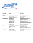
Pond overflows when filling
Verify valve is installed upright, flow
direction is correct and manual fill screw
is tight.
Readjust sensor height to lower water
level.
Verify proper connection with the white
wire from the sensor.
Fountain or Water Feature may not
have filled within time (see operation
note).
Fountain or Water Feature will not fill
Check to make sure power is available
at receptacle.
Check for debris on sensor and clean
per instructions.
Check to ensure valve connections are
tight and that the wires are not
damaged.
Warranty
Aquility Systems, Inc warrants this product to the original
purchaser for a period of one year against defects in material
or workmanship when used for normal residential purposes it
is intended for. In order to obtain a replacement unit or repair
the existing unit, you must obtain a RMA number and return
the complete unit, postage prepaid, to the place of purchase,
or to the Aquility Systems facility. (6949 SW 21st Lane,
Gainesville, FL 32607)
This warranty is intended to cover product defects only.
Aquility Systems, Inc. is not liable for indirect, incidental or
consequential damages in connection with the use of the
Level Waters product covered by this warranty. This
warranty does not cover any cost or expense incurred by the
purchaser in providing substitute equipment or service
during reasonable periods of malfunction or non-use of this
product, while waiting for completion of repairs under this
warranty. Some states do not allow exclusions of incidental
or consequential damages, so the above exclusions may not
apply in all states. This warranty gives you specific legal
rights in your state, which vary from state to state.
If you wish to contact Aquility Systems, Inc., please direct
inquiries to:
Customer Service
Aquility Systems, Inc.
6949 SW 21st Ln.
Gainesville, FL 32607
or:
[email protected]