1
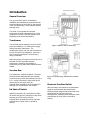
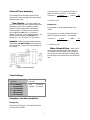
SECTION B TROUBLESHOOTER’S GUIDE
PROBLEM
CAUSE
SOLUTION
Insufficient water flow to
chlorinator
Check water flow through spray nozzles
Clean spray nozzles with compressed air
Inlet Shutoff Valve closed
Emergency Shut Off Switch in closed position
Solenoid Valve not operating properly
Open Inlet Shutoff Valve
If ESS Valve is stuck, lower gently to reset
Check with Dealer
Insufficient chlorine in pool
Feed rate/output too low
Chlorinator empty
No/low inlet water flow
Outlet Shutoff Valve closed
Clogged Discharge Tubing
Briquettes stuck together
Clogged Briquette Tank Grid
Clogged Venturi System
Increase feed rate/output on timer or ORP unit
Refill Briquette Tank with Pulsar® Plus Briquettes
See insufficient water flow section
Open Outlet Shutoff Valve
Refer to Section A or Replace discharge tubing
Tap side of Briquette Tank to loosen
Refer to Section A
Remove and soak in dilute Pulsar® Acid cleaner 50
Excess chlorine in pool
Automatic Controller Problem
Feed rate/output too high
Refer to automatic controller manual
Decrease feed rate/output on timer
Air leaks
Discharge Tubing not properly installed in fittings
Discharge Valve seat failure
Scale prevents Discharge Valve from properly
seating
Pinched O-rings in Tubing Connectors
Reinstall Discharge Tubing
Replace Discharge Valve Arm.
Remove Discharge Valve Assembly and soak in
dilute Pulsar® Acid Cleaner 50 to remove scale
Inspect O-rings on discharge side of feeder
Chlorinator overflow
Discharge Tubing clogged
Insufficient outlet suction
Emergency overflow switch failure
Refer to Section A or Replace Discharge tubing.
Check with Dealer
Check with Dealer
Introduction
General Overview
The purpose of this guide is to familiarize
installation and maintenance personnel with the
electrical functions of the Pulsar IV and to assist
in the "troubleshooting" of any electrical failures
that may occur.
The Pulsar IV incorporates six electrical
components and their associated wiring. Each
component is critical in the safe operation and
dispensing of the chlorinated solution.
Transformer:
The electrical system operates from a 24 Volt AC
source provided by a U.L.-listed class-II energylimiting step-down transformer. The
transformer's primary coil (the side connected to
the 120 Volt source) is designed to "open like a
fuse" when the transformer's VA (Volt Amp.)
rating is exceeded.
Figure 1 Junction box terminal strip
When the primary coil opens the 24 Volt source is
removed from the secondary electrical
components, preventing over-heating of
components, wiring and possible electrical shock
hazard.
Junction Box:
The transformer, Lid Shut-off Switch , Electronic
Overflow Switch and Solenoid/Timer Assembly
are wired to the junction box terminal strip (Fig. 1
& 2). A relay is mounted in the junction box to
remove the 24 Volt supply from the
Solenoid/Timer Assembly if the chlorinator lid is
removed or if the chlorinator tank overfills.
Figure 2 External wiring Junction Box Terminal
Strip
Electronic Overflow Switch:
When the water level reaches a pre-determined
height in the chlorinator tank the Electronic
Overflow Switch energizes the junction box relay
removing the 24 Volt source from the
Solenoid/Timer Assembly which causes the water
solenoid valve to close (refer to manual for
picture).
Lid Shut-off Switch:
When the chlorinator lid is opened the Lid Shutoff Switch energizes the junction box relay which
removes the 24 Volt source from the
Solenoid/Timer assembly and causes the water
solenoid valve to close (refer to manual for
picture).
1
Total cycle time = A (19 seconds “off time”) +
HIGH (30 seconds “on time”) = 49 seconds
% on time =
on time
x 100 or
30
Total cycle time
49
Solenoid/Timer Assembly:
The Solenoid/Timer Assembly consists of the
timer module which is plugged into the solenoid
actuated water valve.
= 61.2% on time
Timer Module: The timer module (Fig.
4) turns on and off the water solenoid valve at an
adjustable on/off cycle to maintain a balance
between the inlet water and the discharged
chlorine solution. The timer has two controls -one to adjust the ON time to: 11 seconds =
Normal, 22 seconds = Low, and 30 seconds = Hi;
and the second to adjust the DELAY time in
seconds (i.e., A = 19 secs to G = 53 minutes).
Example #2:
Top Knob set to “B” and Bottom Knob set to
“LOW”
Total cycle time = B (192 seconds “off time”) +
LOW (22 seconds “on time”) = 214 seconds
% on time =
WARNING: While turning the upper and lower
timer knobs, DO NOT FORCE the knob beyond
their stop points. Doing so will cause damage to
the controls.
22
214
= 10.28% on time
Water Solenoid Valve: When the 24
Volt source is applied from the timer module to
the solenoid coil of the water valve a magnetic
core retracts into the solenoid coil allowing water
to flow through the valve and into the chlorinator
tank.
Figure 3 Simple schematic
Timer Settings:
Top Knob
(off time)
A – 19 seconds
B – 3.2 minutes
C – 14.0 minutes
D – 27.0 minutes
E – 39.0 minutes
F – 50.0 minutes
G – 53.0 minutes
on time
x 100 or
Total cycle time
Bottom Knob
(on time)
High
– 30 seconds
Low
– 22 seconds
Normal – 11 seconds
Examples of on time calculation:
Example #1:
Top Knob (off time) set to “A” and Bottom Knob
(on time) set to “HIGH”
2
Troubleshooting Guide
Step-by-step Electrical System Test
1. Close water inlet and outlet valves
2. Verify that the Power transformer is plugged
into a wall receptacle that has been tested to
verify that power is present. Verify timer module
power light is on (see Fig. 4).
If power is on go to next step, if not meter test.
Figure 4
3. Lift the hopper off the base -- does the power
light go out?
Replace the timer if defective and go to the next
step.
If light goes out replace the hopper on it's base
and go to next step, if not go to the meter test.
6. Set the upper control knob to the "A" (19
seconds solenoid on time) position and the lower
control knob to the "normal" (11 seconds solenoid
off time) position. Verify that the timer module
power light is on. Watch the valve light. It
should come on for 11 seconds and off for an 19
seconds. During this test the solenoid valve will
click at the start and end of the duty cycle and
may hum while the valve light is on. This verifies
that the solenoid coil is not defective. If the
solenoid valve does not click on then vibrate
during the on portion of the duty cycle the
solenoid coil of the solenoid water valve must be
replaced. If the light cycles on and off, go to the
next step. If not the timer module is defective
and must be replaced.
4. Lift hopper lid with your hand. Did the power
light go out?
If yes, then press the lid switch down and hold,
did the light come on?
If yes then while depressing the lid switch reach
under the deflection plate and lift the electronic
overflow switch, did the light go out?
If yes, then the lid and electronic overflow
switches are functioning properly and the 24 Volt
power source is applied to the timer module. Go
to the next step.
If not go to the Meter Test.
7. Turn both the inlet and outlet water valves on
to verify that water is available and watch for
water flow. When the timer module valve light is
on and the solenoid coil is vibrating the water
should begin to flow. When the timer module
light is off the solenoid coil should stop vibrating
and the water should stop flowing. If the valve
comes on and off then the electrical system is
performing correctly. If the water fails to start or
stop flowing then the valve portion of the
solenoid water valve is defective and must be
replaced or repaired.
READ THE FOLLOWING INSTRUCTION STEPS
BEFORE CONTINUING THE TEST. THE TIMER
MODULE MAY BE DAMAGED IF NOT PERFORMED
CORRECTLY.
5. Turn the upper timer module control knob fully
clockwise and counter-clockwise to verify that the
knob comes to a stop at each end of the rotation.
Be careful not to force the knob beyond the stop.
If the knob rotates fully then the control knob is
broken and the timer module must be replaced.
Perform this test on the lower control knob.
Again DO NOT FORCE the knob.
Restore the timer modules upper and lower
control knobs to their previous times or refer to
the owners manual for instruction.
3
METER TEST
The following tests should be performed utilizing
a volt meter (ref. Fig.5 – detailed schematic &
Fig.6 -- meter placement). The following test is
performed using a volt meter set on AC Voltage
with a voltage scale set greater than 24 Volts.
The lid of the hopper should be closed and on its
base and the electronic overflow switch should
not be in the up position.
Connect the meter leads to the terminal board
(TB1) as instructed in the following steps (see
Fig. 6).
1. Connect the meter test leads to terminals 1
and 2 of the TB1. The meter should indicate 24
volts. If the reading is correct go to next step.
Figure 5
electronic overflow switch. The meter should
indicate 24 volts with switch in the up position
and return to zero when released.
If no voltage is present, check the wiring to the
power transformer and verify that power is
present at the outlet that the transformer is
plugged into. If the wiring is correct and the
outlet power is verified then the transformer is
defective and must be replaced.
During the next test, remove power to the
junction box between each step by unplugging
the transformer from the power outlet. Once the
wire is removed from the terminal strip and is
isolated, restore power to the junction box and
perform the test.
If 24 volts is always present during the above
tests the hopper lid switch and/or the electronic
overflow switch may be defective and must be
disconnected from the terminal strip TB1 one at a
time. Refer to Fig. 1 and disconnect the wire to
terminal 3 of TB1. Observe the meter. The 24
volts may or may not return to zero. If the
voltage returns to zero then the lid switch is
defective and must be replaced. If the 24 volts
remain with terminal 3 disconnected leave the
wire to terminal 3 disconnected and perform the
same test with the electronic overflow switch.
Disconnect the wire to terminal 7. Again the 24
volts should return to zero. If not the electronic
over flow switch is defective or is stuck in the
up position. Remove power to the Junction box
and reconnect the wires to terminal 3 and 7.
Figure 6
2. Connect the meter test leads to terminals 1
and 3 of TB1. No voltage should be present.
While observing the meter, lift the lid of the
hopper. The meter should read 24 volts and
return to zero when the lid is replaced.
Lift the hopper off its base. The meter should
indicate 24 volts and return to zero when the
base is replaced.
3. Connect the meter test leads to terminals 5
and 6. If 24 volts is present, but the power light
on the timer module is off, then the timer module
or its wiring is defective. If 24 volts are not
present then the relay RY1 is defective and must
be replaced.
Lift the hopper lid and press down the lid switch.
Reach under the deflection plate and lift the
4