1
Addition of new 5800 series transmitters with
this control panel is prohibited, other than for
repair of existing installations. Non-permitted
use voids U.S. warranty.
ADEMCO
Wa 30+
SECURIN SYSTEM
Installation Instructions
N7225V15/94
ADEMCO
CONGRATULATIONS!
On Your Purchase
of the Adernco wia30+
The purpose of these Installation Instructions
instructions for installing a basic system.
is to give you a complete overview of the system, and provide
CONTACTING TECHNICAL SUPPORT
PIEASE,
Beforeyou callTechnicalSuppo@ be sureyow
READ THE INSTRUCTIONS!
Check all wiring connections.
Determinethatthepower sup@y and/orbackupbatteryare supplyiugpropervoltages.
Veri& your programming informationwhere applicable.
Note the proper model number of this produ~ and the version level (if known) along with any
documentationthatcamewiththeproduct.
Note your ADEMCO customernumber and/or companyname.
Having this information handy will make it easier for us to serve you quickly and effectively.
You may contact Technical Support via Toll Free Fax. Please include your return fax number. You will
receive a reply within 24 hours. You may also contact Technical Support via modem to ATLIS-BBS, Tech
Support’s Electronic Bulletin Board System. Replies are posted within 24 hours.
East Coast Technical Support: 1-800-645-7492 (8 a.m.-6 p.m. E.S.T.)
West Coast Technical Support: 1-800-458-9469 (8 a.m.-5 p.m. P.S.T.)
Technical Support Fax Number: 1-800-447-5086
ATLIS-BBS Electronic Bulletin Board System: 1-516-496-3980
(1200 -9600 Baud, 8 Data Bits, 1 StarttStop Bit, No Parity)
The Ademco via30+ System
Can Support 2 EOLR WiredZones
(when used with an appropriate
and
wireless receiver and/or wired expansion
module)
Up to a Totalof 30 ExpansionZones
(Comprisingany combinationofiup to 30 Wireless and/orup to 8 AdditionalWired Zones)
and
(when used with an appropriate output relay module)
upto40utputkilays
The SystemCan Also Supporh
TelephoneVoice Module (No.4285)
and
Long Range Radio Reporting
(via No. 7720ECP)
FOR YOUR CONVENIENCE,
a Programming
Form
has been included at the center of this manual.
–2–
W
Section
1. GENERAL
INFORMATION . ... ......... . 4
introduction ... ........................ .............................4
Zone Characteristics .............................................5
Section 2. SYSTEM CONFIGURATIONS . . . . . . . ...6
HARD WIRED ZONES ...............................................6
Zones 5&6(B*ic Control'sZones) .............. ...... ......6
wlREDzoNE Expansion ..... ..... ........... .....<..... .......7
Nos. 4219and 4229 ExpansionModules....... ............7
WIRELESS EXPANSION, -5700 & 5800 RF SYSTEMS- ...8
General ... .............................. .............................8
Supervision .........................................................8
House identification ..............................................9
Transmitter identification..... ..... .............................9
RF System InstallationAdvisories... ............ ...... ......9
5800 SystemTransmitter Installation Options........... 10
RELAY OUTPUTS .................................................. 11
Nos. 4204 and 4229 Output Relay Modules.............. 11
4204Setup ...... ...................... ........... ................ll
4229 Setup ...... ........... ........... ........... ................ll
Section 3. MOUNTING THE CONTROL,
LOCK, & PC BOARD . . . . . . . . . . . . . . . . . 12
Mountingthe CaMnet ............... ...........................l2
installingthe Lock (if Used) .... ....... .......................12
Installingthe Control’sCircuitBoard Alone,
or (if used), with a 4219, 4229, or 4204 .................... 12
InstallingControland RF Receiver CircuitBoards
Together, in the Same Cabinet... .......................... . 13
UsingOptionalVoice Moduleor Long Range Radio. ... 13
Section 4. WIRING & POWERING
THE SYSTEM . . . . . . . . . . . . . . . . . . . . . . . . . . 14
Grounding the System ......................................... 14
Terminals and Connetiions .... ..............................l4
Power.up Prwedure ..... ... ........ ...........................l5
‘Section 5. PROGRAMMING THE SYSTEM, . . . . ..16
General Information ................ ........................... 16
Summary of Programming Commands..................... 17
Special Messages............... ...............................l7
PROGRAMMING DATA FIELDS ................................ 18
56)..... 20
Zone Response Type Definitions(underfield ●
Relay Basics (under field *80) .... ...........................24
ALPHA DESCRIPTION ENTRIES ... .................... .......27
Assigning Zone Descriptors..................................27
Entering Zone Descriptors....................................27
AddingCustomWords... ........... ......... ..................28
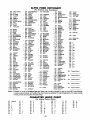
ALPHA FIXED DICTIONARY
(For Entering Zone Descriptors)................................ 29
CHARACTER (ASCll)CHART ........ ........... ................29
-3-
Section 6. SYSTEM COMMUNICATION . . . . . . . ...30
Repoti Code Fomak ..........................................3O
Section 7. REMOTE PROGRAMMING AND
CONTROL (DOWNLOADING). . . . . ...32
General information............................... .............32
Equipment Required............................................32
Pr~ramming .....................................................32
Remote Programming Advisory Notes..................... 32
Section 8, SYSTEM OPERATION . . . . . . . . . . . . . . ...33
sEcuRlm coDEs ................................... .............33
Master Code ......................................................3
User Cdes ...............................<.......... ....c........W
KEYPAD~NCTIONS ............................................W
General information............................... .............33
Aming Functions.................................. .............W
Panic Keys ...... ... .............................. ................34
Relay Outputs (if used)........................................34
ExitAlarm Displays(if programmed)........ .......... .....35
TROUBLECONDITIONS.........................................35
General information....................... ........ .............35
“Check and “Battery”Displays.... ............ .............35
Power Failure.....................................................35
Other Displays (Fixed Word Consoles).................... 35
Section 9. TESTING THE SYSTEM . . . . . . . . . . . . ...36
Procedure .........................................................36
Section
10. SPECIFICATIONS
&
ACCESSORIES
. . . . . . . . . . . . . . . . . . . ...39
sPEclFlcATloNs ... ................ ................. .............39
ACCESSORIES (COMPATIBLE DEVICES) .. .... ...........41
FCC STATEMENTS . . . . . . . . . . . . . . . . . . . . . . . . . . . . . . . . . . 48
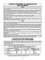
CANADIAN DOC STATEMENT . . . . . . . . . . . . . . . . . . ...49
CSFM 24 HR BATTERY BACK-UP . . . . . . . . . . . . . . ...49
LIMITATIONS OF THIS ALARM SYSTEM . . . . . ...50
INDEX . . . . . . . . . . . . . . . . . . . . . . . . . . . . . . . . . . . . . . . . . . . . . . . . . 51
LIMITED WARRANTY . . . . . . . . . . . . . . . . . . . . . . . . . . . . . . . 52
Diaarams
and Tables
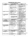
TROUBLESHOOTING
GUIDE . . . . . . . . . . . . . . . . . . . ...37
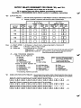
OUTPUT RELAY EXAMPLES
TABLE .. ....... .....44
DIP SWITCH TABLES FOR
WIRELESS
DEVICES . . . . . . . . . . . . . . . . . . . . . . . . . . . . . . . 46
SUMMARY OF CONNECTIONS
DIAGRAM ........47
PROGRAMMING
FORM . . . . . . . . . . . . . . . . . .. Centerfold
Introduction
System
The Ademco via30+ is a microprocessor-based stateof-the-art security control intended for wireless as well as
wired zone applications.
Zones Supported
Supports up to 32 zones, in the following configuration:
2 hard wired EOLR “basic” zones.
Up to 30 expansion zones (wireless and/or additional
wired zones) by using an appropriate RF receiver (4281
or 5881 type) or wired expansion module (No. 4219 or
4229). Refer to the Zone Characteristics tabulation on
the next page for detailed zone information.
Note: The sing/e 4281/5881 type RF receiver that the
Ademco
via30+
accommodates,
features
Spatial Diversity (dual antennas), which virtually
eliminates the possibility of “Nulls” and “Dead
Spots” within the coverage area.
●
●
Alarm Output Advisow
Relay Outputs
2 or 4 output relays can be added, to perform programmable actions in response to zone activity or manual
entries, by using a No. 4229 Wired Expansion/Relay
Module (8 wired zones and 2 output relays) or No. 4204
Relay Module (4 output relays).
‘programming
A No.
5137AD
or 6139
Alpha
Console
is
required
for
programming
zones
and
relay
operation, but it need not remain in the system. These
consoles have digital keypads and 2-line 32 character
alphanumeric LCDS (Liquid Crystal Displays).
Programmed options to establish specific alarm and reporting features are stored in electrically erasable, nonvolatile EEROM memory. This means that the unit can be
reprogrammed many times (unlike units equipped with
PROMS) and that information which has been programmed will not be lost during a complete loss of power.
In addition, the system can be uploaded, downloaded, or
controlled via a computer and Hayes modem (see REMOTE PROGRAMMING AND CONTROL on page 32).
qemote Consoles
After programming, the system may use one or more
4127, 4137 AD, 5137AD, —!
6127 —!
6128 —7
6137 6138, or
6139 Consoles. The underlined models have fixed English status LCDS. The others have alphanumeric displays,
This system includes an alarm
output rated at 2 amps.
Throughout
the manual,
reference
is
wherever
made
to Alarm
Output
Ratings,
they assume
a
fully charged
battery
is
connected, unless the UL
rating is stated. The battery
is periodically tested automatically (approximately every four
hours), and if it cannot sustain a
load, a low battery message is
displayed and can be reported to
the central station.
Note:
Multiple Consoles
(up to 4) may be used, as long
as their total current drain is
within the alarm and auxiliary
power output limitations described in the SPECIFICATIONS
AND ACCESSORIES section.
Nos. 4137AD, 5137AD, 6128, 6137, 6138, and
6139 are Addressable Consoles and must be set
to their non-addressable mode (device ID 31).
When wireless is in use, the system may also be armed
and disarmed with a wireless keypad (No. 5727/5827) or
other 5800 RF button type transmitters (e.g., Nos. 5801,
5802, 5803, 5827BD).
Joice Module
A No. 4285 Voice Module can be connected to the system. It enables Touch-tone telephones to control, and receive messages from, the system remotely. Addressable
type cmso/es must be used (not 4127 or 6127).
Jser Codes
Up to 6 secondary user codes can be assigned by the system’s Master code.
Communication
Communication capability (central station reporting, voice
module accommodation, etc.) over existing phone lines is
provided.
An output for optional Long Range Radio is also provided.
–4–
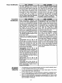
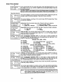
Zone Characteristics
Zones
1-4
not present
Zones
5,6
Wired
Programmable
Zones.
EOLR
supervised,
For more information, N.O. or N.C. sensors, 300-500 msec normal response.
see page 6.
Zones 7, 95, 96 Console Panics (Wired & Wireless). 24hr zones, proFor moreinformation, grammable for silent, audible, auxiliary, or fire.
see page 34.
Zone
8
Duress (see User’s Manual).
Zone
9
Tamper.
Reports faults in the relay module and
expansion units (e.g., 4204, 4219, 4229, 4281, 5881).
For all report formats (except Contact ID, which provides
more explicit reporting) a trouble code is reported when
the system is not armed, and Zone 9 report code is sent
for an alarm.
Additional
Wired
Programmable
Zones
For more information,
see page 7.
Up to 8 loops can be added, with a 4219 Wired
Expansion Module or No. 4229 Wired Expansion/Relay
Module. Loops are EOLR supervised, for N.O. or N.C.
sensors, 300-500 msec normal response, with optional
fast (1 O-15 msec) response on loop A (first expansion
zone). Zone numbers 10-17 should be assigned when
using a 4219 or 4229 for zone expansion.
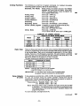
Wireless
Zones
Up to 30 wireless (RF) zones can be added by
For more information, using an Ademco 4281(5700 System) or 5881 (5800
see pages 8-10.
System) Type RF Receiver. Specifically:
Number of Zones
Model
4281 L
4281 M/5881 L
5881 M
4281 H/5881 H
up to 4
Up to 8
Up to 16
up to 30
Zone number assignments (which are also transmitter ID
assignments for 5700 RF system transmitters) can be in
the 10-63 range (18-63 when a 4219 or 4229 is also
used). A variety of RF system transmitters can be used to
make up the wireless zones. This includes window/door
units, smoke detectors, PIRs, and panic keys.
Note: For brevity, subsequent references herein to the
RF Receiver will be indicated by “4281/5881” unless a specific model is named.
If (4219/4229)
wired expansion
zones and
(4281/5881)
wireless
expansion
zones
are to be added,
they can comprise up to 8
(421 9/4229) wired zones, plus wireless zones up to the number permitted by
the type of 4281/5881 RF receiver used, as /ong as the tots/ does not exceea
the 30 expansion zones accommodated by the control
or 4229 are to be used, a 4281 H or
For examp/e: When all 8 loopsofa4219
5881 H can add only 22 zones, so as not to exceed a total of 30
–5-
HARD-WIRED
ZONES
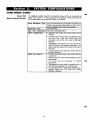
Zones 5&6
(Basic Control’s
Zones)
The Ademco via30+ supports 2 hard-wired zones, which are connected as
zones 5 & 6 (zones 1-4
are not ~resent in this svstem). These zones must be
EOLR supervised, and can use N.O. and/or N.C. s&sors:
Zone
Response
Response
Max.
EOLR
Zone
Type
Time
Resistance
Supervised
Any zone response can be assigned to devices on
these zones except Supervised Fire (09), which
can be assigned only to zone 5 (see below).
300-500 msec.
300 ohms, excluding EOLR
●
●
●
EOLR
Fire
Zone
5
●
●
●
●
●
-6–
Supports both open circuit and closed circuit
devices.
Connect open circuit devices in parallel across
the loop. The 1,000 ohm EOLR must be
connected across the loop wires at the last
device.
hnportant
If the EOLR is not at the end of the
loop, the zone is not properly supervised. The
system may not respond to an open circuit within
the zone.
Connect closed circuit devices in series with the
Hi side of the loop.
Of the 2 hard-wired zones, only zone 5 can be
used for fire.
Supports as many 4-wire smoke detectors as can
be powered.
The zone must be configured
for EOLR
supervision.
The detectors must be wired in parallel, with the
EOLR at the last detector for full supervision.
To supervise power, a supervisory module (e.g.,
System Sensor No. A77-716B
EOL Relay
Module) is required.
WIRED ZONE EXPANSEON
Nos. 4219 and 4229
Exnanslon Modules
If a No. 4219 Wired Expansion Module, or 4229 Wked Expansion/Relay Module is
used, 8 wired EOLR zones can be added to the basic control’s 2 zones, for a total
of 10.
.ocation
Can be mounted within or outside of the Aden?co
vla30+ cabinet (see page 12).
connections
Connects to the control’s remote console terminals for
signaling.
Supervision
. Supewised against removal.
Has tamper protection for security when mounted outside of the cabinet.
●
Zone
Information
Eight wired expansion loops (designated A to H)
should be assigned zone numbers 10-17, and any or
all can be programmed individually (infield *56).
If RF will be used in addition to one of these units (see
WIRELESS EXPANSION sections), any zone numbers
in the range of 18-63 (not 10-17) should be chosen for
the RF zones, even if some of the unit’s wired ex-
pansion loops are not being used.
For example:
If only four of the wired expansion loops are being
used, a 4281 H or 5881 H RF Receiver could add 26 RF
zones (using any zone numbers in the range of 18-63)
to the system, for a combined total of 30 expansion
zones.
If a 4219 or 4229 is not being used, however, the same
receiver could add 30 RF expansion zones to the system, assigned any zone numbers within a 10-63 range.
OFF4+ ON
‘ .-.-.---M2
MM
m
u
*M
~m
Settings
1
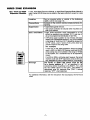
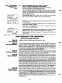
The 421 9’s or 4229’s DIP switch must be set
for a device address of “1”, as described in its
instructions (bottom 3 switches to the RIGHT... ”on”, and
the next switch above to the LEFT... ”of)’’).Switch 1
determines zone A’s response time (“ON” = normal
response, “OFF” = fast response).
For additional information, see the instructions that accompany the 4219 and
4229.
-7-
EXPANSION
General
— 5700 & 5800 RF SYSTEMS —
In addition to its basic wired zones, the control, in conjunction with an appropriate
5700 or 5800 system RF Receiver, can support up to the number of wireless
zones shown below.
5700
RF
Receiver
4281 L
4281 M
4281 H
ON 4-+ OFF
m“
m“
m“
bat
Supervision
SYSTEM
No. of
Zones
up to 4
Up to 8
up to 3ot
5800
RF
Receiver
5881 L
5881 M
5881 H
SYSTEM
No. of
Zones
Up to 8
up to 16
up to 3ot
t In this application
A wireless keypad can also be used with the system (No. 5727 with 5700 System,
No. 5827 with 5800 System, No. 5827BD with either system).
The receiver recognizes status messages and keypad control messages from
Wireless Transmitters operating at 345 MHz (315MHz for the 5700 system’s
Canadian version). These messages are processed and relayed to the control
panel via a 4-wire connection to the control’s remote console terminals. The receiver’s RED, BLACK, YELLOW, and GREEN wires are connected in parallel with
console wiring.
The receiver can be mounted within the control’s cabinet (see page 13) or installed remotely, in its own housing. It can detect signals from wireless transmitters
within a nominal range (installed) of 200 feet.
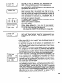
- The receiver’s
DIP switch must be set for a device address
as described in its instructions (all switches to the RIGHT...’’off).
of “O”,
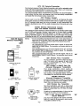
Except for transmitters that may be carried off-premises (such as the 5700 system’s 5701 and 5727, the 5800 system’s 5802, 5802CP, 5803, and 5827, and
either system’s 5827BD), each transmitter is supervised by a check-in signal that
is sent to the receiver at 70-90 minute intervals. If at least one check-in is not received from each supervised transmitter within a 12 hour period, the “missing”
transmitter number(s) and “CHECK” will be displayed on the console.
The supervision for a particular transmitter in the 5800 system may be turned off
by learning it as a “UR” (unsupervised RF) type, as described later.
Each transmitter is also supervised for low battery and will transmit a low battery
signal to its receiver, with the battery having at least 30 days of life remaining. A
low battery message and appropriate zone number will appear on a wired
console’s display.
If a 5727,5827, or 5827BD wireless keypad transmits and has a low battery, it will
be displayed as Zone 00.
Note:
After a low or dead battery is replaced, activate the transmitter and then
enter the security code + OFF to clear the system’s memory of the “Low
Battery” signal.
Some transmitters (e.g., 5800 system’s 5802, 5802CP, and 5803) contain long-life but non-replaceable batteries. At the end of their life, the
complete unit must be replaced [and new identification code(s) learned
by the control... see Transmitter /derttification below].
The receiver itself is supervised. A tamper report (zone 9) will be generated:
a) If communication with the receiver is interrupted.
or
b) If valid RF signals are not received within 12 hours from at least one
supervised wireless transmitter (if any are included in the system).
I
TRANSMITTER
WIRELESS TRANSMITTERS
are described on page 41.
& WIRELESS KEYPAD DIP S WiTCH SETTING TABLES are shown on page 46.
-8–
I
House identification
Transmitter
Identif icatlon
“-5700 SYSTEM
The 4281 reSDOndS onlv to transmitters set to the-same Ho~se ID (01-31,
per the DIP switch tables on page 46)
as programmed in the control’s field
●24. This prevents interference from
transmitters in other nearby systems.
To make sure that a House ID is
chosen that is not in use nearby, conduct the Sniffer Mode test described
under TESTING THE SYSTEM.
5800
SYSTEM
If a 5827 or 5827BD Wireless Keypad
is to be used with the system, a House
ID Code (01-31) must be set in programming field ●24 to establish proper
communication,
and the keypad
shouid be set to the same ID. If no
keypad is to be used, field ●24 should
be 00. DIP switch setting information
5700
SYSTEM
Each transmitter’s
assianed zone
number is DIP switch programmable in
the unit as its transmitter ID (except
wireless keypads, which are fixed at ID
00). Whenever a transmission takes
place, whether for a fault, check-in, or
low battery, the ID number is sent
along with the message to the 4281
which, in turn, relays this information to
the control, which displays the condition and zone number on the console.
5800
SYSTEM
Each transmitter irmut has a different ID
(identification) code, part of which includes a unique serial number permanently assigned to the device during
manufacture. Many transmitters have
more than one input, hence ID code
(e.g., 5801 has 4, 5803 has 3, 5816
has 2, etc.) and each input requires a
The 5827BD Wireless Keypad is keypad programmable.
Certain IDs in the assignment range of
10-63 have the following characteristics:
Transmitters
set for IDs of 3247 will have a 3 minute lock-out between fault transmissions to conserve
battery life (normally PIR units, but
transmitters
protecting trequent/y
used doors and windows should also
be set for IDs in this range).
Transmitters
set for IDs of 4855 (FIRE) will transmit once every 12
seconds while the zone is faulted. This
for a 5827 is given on page 46. The
5827BD is keypad programmable.
separate programming zone.
Itis not necessary to assign a transmitter’s ID(s) during installation. Instead,
the control must learn or be programmed for each transmitter’s ID
code(s) during programming, in conjunction with assigned zone number(s)
and other data. Whenever a transmission takes place, whether for a fault,
check-in, or low battery, the ID code is
sent as part of the message to the
5881. In turn, the information is relayed
to the control, which displays the condition and associated zone number on
the console.
and the next range of zone numbers
have high signal priority and their frequent transmissions while faulted insure retriggering of the a/arm unti/ the
cause is removed.
Transmitters
set for IDs of 5663 will transmit once every 3 seconds
while faulted.
Transmitter
IDs of 62 and 63 are
unsupervised to allow removal of the
5701 off-premises. Signal priority is
higher than burglary.
RF System
Installation
Advisories
1.
2.
3.
4.
If the Receiver is to be mounted remotely (not in the control’s cabinet), place it
in a high, centrally located area for best reception.
Do not locate receiver or transmitters on or near metal objects. This will decrease range and/or block transmissions.
Do not locate receiver in an area of high RF interference (revealed by frequent or prolonged lighting of the LED in the receiver... random flicker is ok).
Before mounting transmitters permanently, conduct Go/No Go Tests to verify
adequate signal strength (see TEST/NG THE SYSTEM) and reorient or relocate transmitters if necessary.
–9-
Transmitter
5800 System
Installation
Options
To install the particular transmitters in a 5800 system, one of two optional methods
can be used. Option 1,whose procedure is described in general below, and in
detail in PROGRAA4WAJG THE SYSTEM on page 16, involves having the system
learn each transmitter to be used in the system. Option 2, described below,
involves the downloader, where the IDs can be entered manually at the office and
then downloaded to an operating system.
oPnolw
7
Learning and Assigning
ID Codes at the Control
With each transmission, each transmitter sends an ID code which includes, in part,
that device’s unique factory assigned serial number. Some devices have more
than one input (sensor point) and that input is also part of the ID code. Each ID
code must be learned and assigned individually to the zone with which it will be
associated.
During programming of the zone, after the device type is entered, the display
“Learn S/N?” will appear. To have the control learn the ID then, pressing [1] will
result in the display “TRANSMIT NOW”.
The control program is now poised at a zone number to be assigned a particular
transmitter input (e.g., of a multi-point contact, single-point motion detector, single-point smoke detector, multi-point emergency transmitter, etc.). A transmitter
will either be akeady installed, or one of a group of transmitters to be installed at a
given site.
The appropriate transmitter input (point) is then activated to cause a complete
event transmission (e.g., by opening and closing a contact, closing and opening
a contact, pressing and releasing a button, causing alarm and restore, etc.).
If the IDcode of this firsttransmissionevent was previously learned, a single, long
error sound is emitted.
/fthe ID code of this first transmission was not previous/y/earned, the assignment
of zone number and ID code (which includes device serial number and sensor
point) is stored in the control memory, and the console emits a single, short
sound to acknowledge this fact and to request a duplicate transmission to verify
the assignment.
A second transmission should then be initiated. Upon reception of a second
transmission, the control compares this second (verify) event with the first (learn)
event,
a) If the two events match, the control keeps the assignment in EEPROM
memoty and the console emits a double, short, acknowledge sound.
The “learned” ID code, together with other system attributes associated
with the particular zone are thus assigned to the selected zone number
for that transmitter’s sensor point.
b) If the second (verifv) transmission does not match the first (learn) transmission. the control awaits another transmission to match the most recently received one. If another matching transmission is not forthcoming,
(within a pre-determined time limit), the assignment is discarded.
Manual
~—
OPTION 2
ID Code Assignment
Method
Supplements REMOTE PROGRAMMING AND CONTROL (DOWNLOADING)
section on page 32.
At the downloader computer location, the downloader for the Ademco via30+
is brought up.
The identification code numbers can be entered at the screens where the zone
characteristics and communicator reporting codes are entered. If the 5800 RF
system has been properly selected (RF expander type 5881 ) on a previous
screen, the type of transmitter and identification code [which includes input (loop)
data... see pages 42 and 43] can be entered on the same line as the other items
for each zone. The factory pre-recorded serial number is read from the nonremovable portion of the transmitter case in a 7-decimal digit (telephone number)
format.
Mark the transmitters to be used in the installation (multi-point contact, singlepoint motion detector, single point smoke detector, multi-point emergency sensor, etc.) and enter their ID codes when programming other data for the system.
When the data that defines the system is downloaded, the identification codes
will be downloaded also and stored in EEPROM memory.
–lo-
~
W
RELAY OUTPUTS
Nos. 4204 and4229
Output Relay Modules
4204 Setup
OFF#ON
N@m
am
~
~m
4229
Setup
OFF++ ON
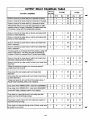
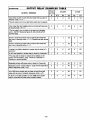
The Adernco vla30+ can support relay outputs via the use of either a4204
(4 outputs) or a 4229 (2 outputs). These modules provide form C (normally open
and normally closed) dry contacts on relays that can be programmed to activate or
deactivate to perform some action in response to a predetermined event such as
turning on lights and/or closing a fire door in the event of a fire alarm condition.
There are many different uses for these relays, some of which are suggested in
the table on page 44.
The unit can be located inside the control’s cabinet or remotely (see MOUNTING
THE CONTROL, LOCK, & PC /30Af?D section and the instructions that accompany the unit).
The 4204 Relay Module has 4 Form C relays. Each relay can be used
independently for different functions. The following steps should be taken to
properly set up the 4204:
1. Connect
the 4204 to the control’s
remote
console
terminals
(4-7), using standard 4-conductor twisted cable (for long wiring runs) or the
connector supplied with the 4204 (as shown in the Summary of Connections
diagram).
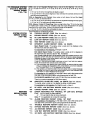
2. Set the 4204’s DIP switch for a device address of “1” (switch 2
“OFF” and switches 3, 4, 5 “ON”). Switch 1 determines the unit’s cover tamper response (“ON” = disabled, “OFF” = enabled).
Note: Some “early” units have only a 4-position DIP switch.
Set 1 to “OFF” and 2,3,4 to “ON”.
3. During programming
(summarized here, but see the detailed procedure
in the PROGRAA4MiNGTHE SECURITY CONTROL section):
a. Program a “3” in field *25.
b. Program fields *8O (Output Relays) and “81 (Zone Lists) for the desired
relay responses.
4. Connect the desired field wiring to the unit’s relay contact terminals.
The 4229 Wired Expansion/Relay Module has 8 hard-wired zones and 2 Form C
relays. Each relay can be used independently for different functions. The
following steps should be taken to properly setup the 4229:
1. Connect
the 4229 to the control’s
remote
console
terminals
(4-7), using standard 4-conductor twisted cable (for long wiring runs) or the
connector supplied with the 4229 (as shown in the Surnrnaty of Cormecfions
diagram).
Set the 4229’s DIP switch for a device address of “1” (switch 2
“OFF” and switches 3, 4, 5 “ON”). Switch 1 determines zone A’s response
time ~ON” = normal response, “OFF= fast response).
During programming
(summarized here, but see the detailed procedure
in the PROGRAMMING THE SECURITY CONTROL section):
a. Program a “2” in field ●25.
b. Program fields *8O (Output Relays) and *81 (Zone Lists) for the desired
relay responses.
c. In field ●56 (zone ~roaramming), assicin zone numbers 10-17 to the
4229’s wired “expansio~ zones. ‘“”
4. Connect the desired field wiring to the unit’s relay contact terminals.
Output
Relay
Advisory
/fa re/ay is energized before a wired smoke detector is reset, the relay wi// be
stopped by the interruption of Aux. Power that resets the smoke detector. If this
is not desired, the power to the relay module should be supplied from another
12V power source (e.g., the same source that is powering external equipment
through the relay contacts).
-11–
Mounting the Cabinet
installing the Lock
(if Used)
secured wthout a lock by using
The Ac/emco via30+ is supplied with a 12-1/2” (318mm) wide x 14-1/2”
(368mm) high x 3“ (76mm) deep cabinet suitable for use in residential
installations.
Mount the control cabinet to a sturdy wall using fasteners or anchors (not
supplied) in a clean, dry area which is not readily accessible to the general public.
4 mounting holes are provided at the back of the cabinet.
Use an Ademco No. N6277 Cam
Lock and No. N6277-1 Push-On Clip
(Retainer Clip).
1. Remove the cabinet cover. It k
/
easily removable for servicing
and is easily reinstalled.
=
2.
3,
installing the Controi’s
Circuit Board Aione,
or (if used), with a
4219, 4229, or 4204
IMPORTANT!
installing
Before
contents,
cabinet’s
the
sure to remove
propriate
metal
the
be
apcabinet
knockouts.
DO NOT ATTEMPT TO REMOVE THE KNOCKOUTS AFTER THE CIRCUIT BOARDHAS
BEEN INSTALLED.
Remove the lock knockout from
the control cabinet cover, Insert
the key into the lock. Position
the lock in the hole making certain that the latch will make contact with the latch bracket when
the door is closed.
a
ESA%l&
o
LOCKEO
\
While holding the lock steady,
insert the retainer clip into the
retainer slots. Position clip as illustrated to facilitate easy removal.
RETAINER
SLOTS
f
UNLOCKED
CA21NE7Dx%l Sm-lml
Control’s Circuit Board
1, Hang two /ong mounting clips (provided) on the raised cabinet tabs (see Detail B below).
2. Insert the top of the circuit board into the slots at the top of the cabinet. Make
sure that the board rests on the correct row (see Detail A).
3. Swing the base of the board into the mounting clips and secure the board to
the cabinet with the accompanying screws (see Detail B).
4219, 4229 or 4204
1. Insert self-tapping screws (provided) in two adjacent raised cabinet tabs.
Leave the heads projecting 1/8”.
2. Hang the unit on the screw heads via two of the slotted holes at the rear of its
housing, as shown.
3. The 421 9’s or 4229’s cover can be left off if the cover tamper jumper is placed
in its upper (not tampered) position (see Detail C). The tampered cover is
necessary for installations outside of the control’s cabinet.
.
4219,
4229, or
4204
NOT TAMPERED
TAMPERE
Q
0
o
0
4219/4229
COVER TAMPER
JUMPER
-1 2–
—
~
Installing
Control and
RF Receiver
Circuit Boards
Together,
in the Same Cabinet
IMPORTANT!
installing
Before
the
cabinet’s
contents,
be
sure to remove the appropriate
metal
cabinet
knockouts.
DO NOT ATTEMPT TO REMOVE THE KNOCKOUTS AFTER THE CIRCUIT BOARDS
HAVE BEEN INSTALLED.
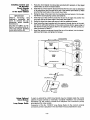
1. Hang two short (black) mounting clips (provided with receiver) on-the raised
.,.
.
cabinet tabs, as shown in Detail B below.
z. Insert the top of the receiver board (removed from its own case as described
in its instructions) into the slots at the top of the cabinet (see Detail A). Make
sure that the board rests on the correct row of tabs.
3. Swing the base of the board into the mounting clips and secure it to the cabinet with the accompanying screws (see Detail B).
4. insert the top of the control’s board into the slot in the clips and position two
/ong (red) clips at the iower edge of the board (see Detaii C).
5
Swing this board into place and secure it with two additional screws.
~“
Insert grounding lugs (supplied with the receiver) through the top of the cabinet into the /eft-hand terminals of the antenna blocks (at the upper edge of
the receiver board) and secure them to the cabinet top with the screws provided, as shown in Detail D.
7. Insett the receiver’s antennas through the top of the cabinet, into the blocks’
right-hand terminals, and tighten the screws.
f
-
HOLES FOR ANTENNAS
AND GROUNDING LUGS
t
BOARD SUPPORTING
SLOTS
RECEWSR
CIRCUIT
90ARD
;:IUT
CABINET
~
DETAIL A
SIOE VIEW OF
BOARD SUPPORTING SLOTS
“SHORT
Mouwmm
I
CUPS \
CONTROL
CIRCUIT
BOARD
LONG MOUMTINO
@
inl
SCREW
~
T
OSTAIL B
SIDE VIEW OF
SHORT MOUNTING CLIPS
CLIPS
ANTENNA
DETAIL C
SIDE VIEW OF
LONG MOUNTING CLIPS
-7!7Q
GROUNDINGLUG ‘
ii/,’ ,, ,,.
0
,,
,,’
DETAILD
ANTENNA
AND
GROUNDING
LUG
INSTALLATION
RCVRBOARD
41!!!!!I!!!!
Using Optional
Voice Module
Long Range Rad;~
CABINET
If used, an optional No. 4285 Voice Module may be installed inside the control
cabinet (if space permits) or externally. Complete installation and connection
information (to the control’s console and telephone line connection points)
accompanies the voice module.
Connection of the No. 7720ECP Long Range Radio (to the control’s console
connection points) is described in the information that accompanies the radio.
-13–
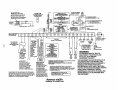
(See Summary of ConnectIons
IMPORTANT:
Grounding
the System
Terminals and
Connections
Diagram on Page 47)
Do not connect the battery, or plug In the AC transformer,
until all other wiring connections have been completed.
Terminal 21 is the earth ground connection point. in order for the protective
devices in this product to be effective, the designated terminal must be
terminated in a good earth ground. The following are examples of good earth
grounds available at most installations:
Metal ccld water pipe: Use a non-corrosive metal strap firmly secured to the
pipe to which the lead is electrically connected and secured.
AC power outlet ground: Available from 3-prong, 120 VAC power outlets
only. To test the integrity of the ground terminal, use a 3-wire circuit tester with
neon lamp indicators, such as the UL Listed Ideal Model 61-035, or equivalent,
available at most electrical supply stores.
1 &2:
3:
e
AC Input (16.5VAC, 25VA) from No. 1321~F2 plug-in transformer
(in U.S.A.j,
“
Note: For Canadian installations, a No. 1321 CN transformer must be
used.
Alarm relay output(+), 12VDC, 2.OA maximum.
600mA max (Alarm phs Aux Power) for UL usage.
OPTIONAL
4:
Ground (-). Return for Alarm Output, Auxiliary Power and Wired Fire.
For Console
and 4281/5881, and 5800TM, and/or 4219/4229/4204.
VI.
5:
+12VDC outuut [at 500mA max.) for Auxiliary Power and Wired Fire.
For Console
and 4281/5881, and 5800TM, and/or 4219/4229/4204.
Via RED leads.
6:
M
from Console
421 9/4229/4204, Vi
~.
7:
~
to Console
and 4281/5881, and 5800TM, and/or
421 9/4229/4204. Via YELLOW leads.
4285 VOICE MODULE
and
7720ECP
LONG
RANGE
RADIO
Use of these devices
in conjunctionwith
/ Connection
Consoe
ter~::jalr4-7
phoneterminals17-20
is describedin the
instructions that accompany
those devices.
and 4281/5881, and 5800TM, and/or
8-13:
not used (Zones 14 not present)
14: Zone 5. (When Zones 5 and/or 6 are used, a 1,000 Ohm EOLR should be
wired between the farthest sensor connected to the zone terminal and the
low side of the zone.)
15: Zones 5 and 6 Return.
16: Zone 6
17:
Handset (TIP).
18:
Handset (RING).
19:
Incoming Phone Line (TIP).
20:
Incoming Phone Line (RING).
EARTH GROUND (a proper earth ground must be provided to protect the
21:
system from lightning and electrostatic discharge damage).
To prevenf the risk of e/ectrica/ shock, disconnect the te/e@?oneMe
at the Telco jack before servicing the unit.
Warning:
RED
LEAD:
Battery (+). When AC is present, 13.8VDC is being developed to
recharge a gel lead acid battery and when AC is absent, 12VDC current is
drawn from the battery. Battery lead reversal will blow the battery fuse.
BLACK
t
LEAD:
Battery (-).
Up to 4 consoles may be used (check total auxiliary current, per SPEC/F/CAT/ONS). Consoles need not necessarily be on individual home runs, but
no more than 220’ of #22 wire or 550’ of #18 wire should be used for each
run.
Addressable consoles (e.g., 4137AD, 5137AD, 6128, 6137, 6138, and
6139) must be set to their non-addressable mode (device ID 31 ).
–14-
-
Power-up
Prooeduro
1. Make sure that the total current to be drawn from the Alarm Output terminals
(3 &4) and Auxiliaty Power Output terminals (4 & 5) does not exceed the
values indicated in the SPEC/F/CAT/ONS section and on the SUMMARY OF
CONNECTIONS diagram.
2. Wire the transformer to the panel (before connecting the battery) as shown
on the SUMMARY OF CONNECTIONS diagram. Do not plug in at this
time.
3. Connect all loops, devices, consoles, etc. to the panel.
4. Plug the transformer into a 24 hour, uninterrupted AC outlet. After some initial displays (see page 17) and approximately one minute, the green POWER
or READY LED on the console(s) should be lit and the consoles should display “READY” (Fixed Word consoles) or “DISARMED READY TO ARM”
(Alpha consoles).
5. Connect the battery as shown in the SUMMARY OF CONNECTIONS
diagram.
-
-15-
General
Information
Installer options are stored in non-removable, electrically erasable, non-volatile
EEROM memory. These options must be programmed for the particular installation to establish its specific alarm and reporting features.
fVote: It is possible to program the system at any time, even at the installer’s
premises prior to the actual installation. Simply apply power temporarily to
the control and then rxoaram
the unit as desired.
.-
-
9
THE SECURITY
CONTROL
IS PROGRAMMED
VIA A
5137AD OR 6139 ALPHA CONSOLE
(or a download)
These consoles need not necessarily remain in the system after programming.
Note; These addressable consoles must be set to their non-addressable mode
(device ID 31).
The initial sequence of entries should follow the order on the programming
sheet.
Certain programming fields, such as those used to select the expansion devices
(fields ●22 and *25) must be programmed before expansion zones can be programmed. If an expansion unit type is changed, the expansion zones should be
reprogrammed.
When programming, the field number will be displayed on the LCD display; also,
each entry is displayed as it is keyed in. After programming, values that have been
entered in each field can be reviewed and, if necessary, modified.
When programming from the console, note the following:
1. Enter the Programming mode by simultaneously depressing the [~] and [#]
keys within 50 seconds after power is applied to the Control, or
subsequently by keying the code 4 + 1 + 1 + 1 followed by depression of
CODE + O keys. If a different Master code is subsequently programmed,
use it instead of 4111 to gain access to the Programming mode. If the Pro-
gramming mode was exited previously using a *98, it will prevent entry into
the Programming mode by the use of the Master Code+ CODE+ O.
2.
Immediately following entry into the program mode, field *2O will be displayed.
Following the above display, the system is ready to accept entries for field
●20.
3. To program a data field, key [x] plus Field No. (for example, ++21), then
make the reauired entrv.
Some entries require sequential pressings of [~] to actually enter the data. This is
true in the Zone and Relay fields *56, “80, and *81 and the prompts will indicate
this. Entry of [#] will generally back up one entry position for review.
4.
5.
6.
7.
To simply review a data field, key [#] plus Field No.. Data will either be automatically sequentially displayed or can be displayed by successively pressing [#]. No changes will be accepted in this mode.
When a data field has been completely programmed, the console will normally
“beep” three times and then automatically display the next data field number
to be programmed (if not, key [~] plus the Field No. of the next field to be
programmed).
If the number of digits that you enter in the data field is less than the maximum
permitted (for example, phone number), then the console will display the last
data entered. To proceed, the next data field number to be programmed
must then be entered (for example, X42).
If a field is improperly entered, the console will display EE. Simply re-enter
[++]or [#] PIUSthe field number.
-16-
Summary
of
Programming
Commands
FUNCTION
ENTER PROGRAMMING MODE
INITIALIZE DOWNLOAD ID
AND
SUBSCRIBER ACCT NUMBER
FOR DOWNLOADING
OR
2. Initially, key: 4 + 1 + 1 + 1
plus CODE key + O.
OR
3. If different Master Code is programmed,
key:
MASTER CODE + CODE KEY + O.
(if +K98was used to exit previously,
method 1 above must be used to enter
the program mode again)
X96
No data entry required,
loads defaults.
+$97 No data entry required.
X98
ERASE FIELDS
READ FIELD
OC =
‘“
POWER UP, then depress
[~] and [#] both at once, within
50sec of powering up.
TO DEFAULT VALUES
EXIT PROGRAMMING MODE
PROGRAM FIELD
Messages
1.
SETALLPROGRAMFIELDS
ADVANCE TO FIELD
Special
PROCEDURE
Inhibits re-entty to programming
mode via type 2 or 3 entry method
above.
X99
Allows re-enhy to programming
mode via type 2 or 3 entry method.
[~] + Field No. (e.g., 21, 38, 56, etc.)
[~] + Field No., followed by data entries.
Some fields require sequential pressings of
[~] to enter data (e.g., fields 56, 80, 81).
[~] + Field No. + [~] (only applies to
fields 40 thru 43 and 94).
[#] + Field No. Data will either be
automatically sequentially displayed or can
be displayed by successively pressing [#].
OPEN CIRCUIT(no communication between Console and Control).
ERROR (program entry mistake). Re-enter the field number or data).
EE =
After powering up, AC, dl (disabled) or System Busy and NOT READY will
be displayed after approximately 4 seconds. This will revert to READY in appx. 1
minute, which allows PIRS, etc. to stabilize. To bypass this delay, press: [#]+ [0].
If E4 or E8 appears, more zones than the expansion units.can handle have been
programmed. Correct the programming and then completely de-power and repower the control to clear this indication and remove the disable indication.
-17-
PROGRAMMING
DATA FIELDS
1
THE CENTERFOLD PROGRAMMINGFORM CAN BE USED TO RECORDTHE DATAFOR THIS INSTALLATION
SYSTEM SETUP
(“20 -’27)
MASTER
CODE
Enter 4 digits, O-9 (entry of all 4 is mandatory).
Use of a “9” in the last position inhibits the duress code feature.
*21
QUICK ARM ENABLE
If enabled, [#] key can be used instead of security code when arming .
Code is always required when disarming.
Enter O for disabled or 1 for enabled.
*22
RF SYSTEM TYPE
Select the RF system (receiver) type being used.
O = none; 1 = 5700 (4281); 2 = 5800 (5881 )
*23
FORCED
BYPASS
FUNCTION
All zones that are bypassed by this function will be displayed after the
bypass is initiated.
O = No forced bypass.
ZONE SOUNDS AND
TIMING
(*28-*39)
I
*2O
1 = Allows quick bypass of all open zones.
*24
RF RECEIVER
HOUSE ID CODE
MUST enter for 5700 system’s 4281 type receiver, or 5800 system’s
5827 Wireless Keypad or 5827BD Bidirectional Console.
Enter 01-31 House ID.
*25
WIRED
EXPANSION/OUTPUT
RELAY
Select expansion/relay module being used.
O = none; 1 = 4219; 2 = 4229; 3 = 4204
*26
VOICE MODULE
ACCESS
CODE
Supports the 4285 Voice Module on the console lines
(the 4285 has a permanent device address of 4).
To enable, enter two digits. 1st digit: 1–9
2nd digit: ‘~’ (enter #+1 1) or %’ (enter #+12)
To disable, enter O in either position.
*27
OUTPUT TO LONG RANGE RADIO (e.g., No. 7720ECP)
Enter O for no or 1 for yes.
If yes is selected, any dialer report programmed to report to the PRIMARY
phone number (in field *47) will be sent, as well, via long range radio. All
dialer m long range radio reports will be in Contact ID fotmat (regardless
of the selection made in field *46).
Note: The Radio should be programmed for a device address of 3
on the console lines.
Full Trouble and Restore messages are sent.
*28
SINGLE ALARM SOUNDING PER ZONE (per armed period)
Affects external sounder only, if yes is selected.
Enter O for no or 1 for yes.
●29
FIRE SOUNDER
TIMEOUT
30).
O = Fire sounder times out at end of bell timeout period (field ●
1 = Fire sounder continues until silenced manually.
●3O
ALARM
BELL TIMEOUT
External sounder will shut off after time allotted. Enter 1 digit.
1 = 4 minutes
3 = 12 minutes
O = No timeout
2 = 8 minutes
●38
ENTRY
DELAY
System will wait the time allotted before sounding alarm upon entering.
(EXIT delay = Entry delay plus 15 seconds)
0= Osec, l=20sec,
2=30sec,3=45sec,
4=60sec,5=90sec.
*39
AUDIBLE
EXIT WARNING
When arming AWAY or MAXIMUM, console sounds slow beeps during exit
time, turning into fast beeps during last 5 seconds.
Enter O for no or 1 for yes.
–18-
USED
~
DIALER
PROGRAMMING
(’40-’50)
Fields ’40, ●41, ●42:
Enterup to the number
of digitsshown.
Do not fill unused spaces.
Enter O-9
#+1 1 for ‘~”,
In
*4O
PABX ACCESS CODE (See box at left)
Enter up to 4 digits it PABX code is needed to access an outside line. If
fewer than 4 digits entered, exit by pressing X (and press 41 if entering
next field). To clear entries from field, press 4+40X.
●41
PRIMARY PHONE No. (See box at left)
Enter up to 12 digits. If fewer than 12 digits entered, exit by pressing X
(and press 42 if entering next field). To clear entries from field, press
*41*.
Note: Back-up reporting (8 calls are made to the secondary phone
number if no kiss-off is received after 8 attempts to the primary
number) is automatic only if there is a secondary phone number.
*42
SECONDARY
PHONE No. (See box at left)
Enter up to 12 digits. If fewer than 12 digits entered, exit by pressing X
(and press 43 if entering next field). To clear entries from field, press
X42X. See Note in field above.
*43
SUBSCRIBER
ACCOUNT.
No.
Enter digits O-9, #+1 l=B, #+12=C, #+13=D, #+14=E, or #+15=F.
Enter X as the fourth digit if a 3 digit ,acct no. (for 3+1 dialer reporting format) is used. Enter O as the first digit of a 4-digit acct no. for nos. 00000999. End field by pressing X (and press next field) if only 3 digits are
used. To clear entries from field, press X43X.
*45
PHONE
SYSTEM
SELECT
Enter 1 digit.
If Central Station Rcvr is noton WATS line:
O = Pulse Dial 1 = Tone Dial
If Central Station Rcvr is on WATS line:
2 = Pulse Dial 3 = Tone Dial
●46
REPORT
FORMAT
Determine format to be used to report to the central station. Enter 1 digit.
#+12 for ‘#,
#+1 3 for a pause
O= 3+1; 4+1 ADEMCO Low Speed Std.
6 = 4+2 ADEMCO Express
7 = ADEMCO Contact ID Reporting
1 = 3+1; 4+1 Radionics Standard
8 = 3+1; 4+1 ADEMCO Low Speed Expanded
2 = 4+2 ADEMCO Low Speed Standard
9 = 3+1; 4+1 Radionics Expanded
3 = 4+2 Radionics Standard
43, if 3+1 dialer reportinfr is to be used.)
(Enter x as the 4th digit of ●
~‘for exp/arMtlon of;hese formats, see page 3;.
Notes:
●47
I
The maximum number of alarm and alarm restore reports during
one armed period is determined by field *92.
27, which may override this field’s selection.
See field ●
SPLIT/DUAL
REPORTING
Enter O to disable (Backup reporl only). To enable, enter 1-5.
TO SECONDARY PHONE No.
TO PRIMARY PHONE
Alarms, Restore, Cancel
1=
Other Reports
Open/Close, Test
2 = All Reports except Open/Close, Test
No.
Alarms, Restore, Cancel
3=
4 = All Reports except Open/Close, Test
All Repotts
(DualReporting)
5=
ARMING DING
(*51)
All Reports
All Reports
All Reports
●48
15 SECOND
DIALER DELAY (BURGLARY)
Allows time for subscriber to avoid a false alarm transmission.
Enter O for no or 1 for yes.
*49
PERIODIC
TEST
MESSAGE
Select the desired test report interval.
O = none; 1 =24 hours; 2 = weekly; 3 = monthly
Test Report Code entered in field *64 is sent.
’50
SESCOA/RADIONICS
SELECT
1 = SESCOA (O-9 only reporting)
O = Radionics (O-9, B-F reporting)
*5 I
CONFIRMATION
OF ARMING DING
Enter O for no or 1 for yes.
If selected, ding is external sounder only and will occur at time of kissoff of
closing report. If closing report is not programmed, ding will occur at end
of exit time.
-19–
ZONE
ASSIGNMENT/
ALARM
REPORT
CODES,
etc.
(*56)
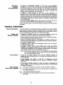
*56
ZONE ASSIGNMENT/ALARM
(and RF Input ID Learning
REPORT
CODES
for 5800 System)
REFER TO TH~ZONEASSIGNMENT TABLE FOR THIS FIELD
ON THE CENTERFOLD PROGRAMMING FORM
This field is used to program zone numbers, zone types, alarm and report
codes, and to identify the type of loop input device. This field can also be
used for “learning” 5800 series transmitter ID codes and for entering alpha descriptors for zones.
EE!Gl
Zone20
entered ~
Zn~-RC
2009-
Zone Number (Zn): Upon entering field ’56, enter the zone number
that you wish to program (or [0][0] to leave zone programming).
ln:L
10
RF:-
Zone Type T
Press [~]. A summary display will come up, showing the status of that
zone’s program.
If it is programmed satisfactorily, press [#] to back up one step and enter
another zone number, if desired.
If the zone is not programmed, or you want to change it, press [~]. A
prompt for Zone Type will appear.
Zone Type (zT): Each zone must be assigned to a zone type, which
defines the way in which the system responds to faults in that zone.
Enter the zone type code (or change it, if necessary). Zone types are
defined beiow.
ZONE RESPONSE TYPE DEFINITIONS
#.
Zno e Tvwe 02 is not used m this svsten?.
Eiiiml
Program a zone with this zone type if the zone is not used.
Zone Not Used
m
Entry/ExitBurglary
This zone type provides entry delay whenever the zone is faulted if the control is
armed in the Away or Stay modes. When the panel is armed in the Instant or
Maximum modes, no entry delay is provided. Exit delay begins whenever the
control is armed, regardless of the arming mode selected. These delays are
programmable. This zone type is usua IIv ass_ian ed to se nsors or contacts on
doors throuah which mimaw entfv and exit will take Dlace.
“
This zone type gives an instant alarm if the zone is faulted when the panel is
EiiEm21
armed in the Away, Stay, Instant or Maximum modes. This zone tvoe is usually
Perimeter Burglary
ass ianed to aII sensors or contacts on exte rior doors a nd windows.
Interior,
m
Follower
EiiimEl
Trouble by Day/
Alarm by Night
This zone type is active when the panel is armed in the Away or Maximum modes,
Entry delay (using the programmed entry time) results if the panel is armed in the
Away mode and the entry/exit zone is faulted first. Otherwise this zone type gives
an instant alarm. Exit delay is present for any arming mode. This zone tvt)e is
Usu allv as sianed to a zone co verina an area suc h as a fever, Iobbv, or hallway
throuah which one must pass (upon entrv, afte r fauiting the entrv/exit zone) to
reach the console to d isar m the svstem. Since this zone type is designed to provide an instant alarm if the entry/exit zone is not violated first, it will protect an area
in the event an intruder hides on the premises prior to the system being armed, or
gains access to the premises through an unprotected area. This zone type is
bypassed automatically
when the panei is armed Stay or Instant.
This zone type will give an instant alarm if faulted when armed in the Away, Stay,
Instant or Maximum (night) modes. During the disarmed state (day), the system
will provide a latched trouble sounding from the console (and a central station
report, if desired). This zone type is usua Ilv assianed to a zone which contains a
foil-Drotected doo r or window (such as in a store). or to a zone coverina ~
II
en sitive” area such as a stock room. drua SUDpIv room. etc. This zone type can
also be used on a sensor or contact in an area where immediate notification of an
entry is desired.
–20-
w
EEa!I!l
24-hour Silent Alarm
This zone type sends a report to the Central Station but provides no console
display or sounding. This Zone tyc)e is usuallv as sianed to a zone containina an
.Eme rgen~~.
m
24-hour Audible Alarm
This zone type sends a report to the Central Station, and provides a rapid
beeping sound at the console, and an audible external alarm. ~
Usua Ilv assianed to a zone that has an Emeraencv button.
This zone type sends a report to Central Station and provides a rapid beeping
sound at the console. (No bell output is provided). This zone tvpe is usuall
in
tozn
~
ntainin
~
a zon containin m ni rin_ evic
m
24-hour
Auxiliary
Alarm
m
Supervised
Interior
This zone type provides a fire alarm on short circuit and a trouble condition on
open circuit. The bell output will pulse when this zone type is faulted. This zone
type is always active and cannot be bypassed. Thi
n be
~o z ne
ntr
I
an
I
wir
wired zon
c~
xDansion
odule. or
cefia in wireless zones.
Fire
Eiiiiml
This zone type gives entry delay (using the programmed entry time), if tripped
when the panel is armed in the Away mode, regardless of whether or not an entry/exit delay zone was tripped first. This zone type is also active during Maximum
mode, but no entry delay is provided (an alarm occurs immediately if the zone is
tripped). Exit delay is present for any arming mode. This zone type is
bypassed automatically
when the panel is armed Stay or Instant .
This is a special purpose zone type used with 5800 series wireless pushbutton or
contact closure or opening, and which will result in arming the system in the STAY
mode when the zone is activated.
w/Delay
EiiizQl
Arm-Stay
This is a special purpose zone type used with 5800 series wireless pushbutton or
contact closure or opening, and which will result in arming the system in the
AWAY mode when the zone is activated.
m
Arm-Away
Disarm
This is a special purpose zone type used with 5800 series wireless pushbutton or
contact closure or opening, and which will result in disarming the system when the
zone is activated.
m
Response
This zone type can be used on a zone when an output relay action is desired, but
with no accompanying alarm (ex. lobby door access).
m
No Alarm
By using a 4281/5881 RF Receiver and the appropriate 5700/5800 series transmitters,
all of the above zone types are available for the wireless poflion of the system.
When the display shows the zone type you want, press [~] to advance
to...
20 Report Code
Ist 00 2nd 00
I
00
I
Report Code (RC): The report code consists of 2 hexadecimal digits,
each in turn consisting of 2 numerical digits. For example, for a report
code of “3C”, enter [0][3] for “3 and [1][2] for “C”. Enter the numbers
and press [*J to advance to...
Input Device (In): For the hard wired zones of the Adernco via30+
(HW), the auxiliary wired expansion zonesona4219
or 4229 (AW), and
the zones for a 5700 system’s transmitters (RF), the Input Device types
are automatically assigned (Panic, Duress, and Tamper inputs are not
applicable).
I20 Input Device
RF Trans. RF:
I
For a 5800 system’s transmitters, “RF” is initially displayed, but should be
changed to “UR” (Unsupervised RF, enter 4) for units that can be carried
off-premises (e.g., No. 5801), or to “BR” (Button type RF, enter 5) for
small transmitters that cannot be supervised (e.g., Nos. 5802, 5802CP,
5803). Check the instructions that come with the transmitter for the
proper input. When all is okay, press [~] to advance to...
–21-
20 Learn S/N ?
O=NO 1=Yes
O
Learning RF Input (L): App/lcab/e
to a 5800 system only.
Note:
Where a “Yes-No” is asked by the console, pressing the
[~] or [0] for No is equivalent.
This request will be to learn the transmitter input’s ID code. (The ID codes
83.)
can be learned here or via field ●
I
F==n
TYPICAL
If “yes” is selected, open and close (or close and open), or press and release the particular input to the transmitter twice. After the first time, a
single short beep will occur. After the second time, two short beeps will
mean that the control has accepted that transmitter into the system. Because of the characteristics of the receiver, allow about 8 seconds between transmissions from button units (e.g., 5802, 5802CP, 5803). If a
long beep occurs, it means that the particular transmitter input has
previously been registered in the system.
The display will revert to the summary line, with the accepted input (loop)
number under the “~ in the display.
Mark the zone number on the transmitter.
If all is okay, press [X].
DISPLAY
m
Accepted Input (Loop)Number ~
O=NO 1=Yes
Custom Alpha Editing: For all zone types, the next request is to
enter alpha descriptors for the zones. The entry may be done now (enter
1) or may be done at a later time via field *82 (enter O).
I
Program Alpha?
O
See the ALPHA DESCRIPTION ENTRIES section on page 29.
When all entries to be made for the zone at this time are complete, the
next zone number can be entered for programming,
or zone
programming can be ended by entering [0][0] as the next “zone
‘1
number
Notes:
●
When using a 5801, the Input (Loop) “4” button should always be used and
learned by the system.
/n fie/d *56, at the summary line for each zone, the entered va/ues can be
checked If it is desired to change anything, press [#] to move to the previous
entry. Press [#] a number of times to move to earlier entries. Press [++]to move
to later entries again.
Zone entries can be reviewed by pressing [#][5][6]. Changes cannot be made
here, so this is safer for review. Enter the first zone number to be viewed and
press [#]. To view each zone, press [#] and the zone number will advance to
the next programmed zone. When the end of the list is reached, press [0][0] to
exit. This method of exiting may also be done at anytime during the review.
To either temporarily or permanent/y remove a zone from the system, go into
programming mode and press ~][5][6]. Enter the zone number and press [~].
At the Zone Type prompt, enter [0][0] and [+$].This sets the type of the zone
to Not Used. The next prompt will be “Delete Zone?”. “Yes” will permanently
remove the zone from the system while “No” will disable it but retain all data except the original zone type. You can then go back to this zone later and put
back an active Zone Type to re-enable it.
An ID code that has been learned for a 5800 system will not be deleted if the
zone is disabled as described above. /f on/y the physics/ transmitter is to be re-
E&cL!!d*
20 Delete Zone?
1=Yes
O=NO
●
moved or changed (i.e., its ID code deleted, as when replacing a unit that has a
non-removable battery), it can be done in fie/d *56 or ●83. In programming
mode, press [X][5][6], enter the zone number, and press [X] multiple times
until the cursor is under the Learned RF Input (L) position. This is the specific
input (loop) or button on the transmitter that has been learned for that zone. If a
[0] is entered at this point, a prompt “Delete S/N?” will appear. If “Yes” is
entered, this specific ID code will be deleted from the system.
-22–
TO PROGRAM SYSTEM
STATUS & RESTORE
REPORT CODES
(“60 -”75]
With a 3+1 or 4+1 Standard Format: Enter a code in the first digit box: 1-9, 0, B, C,
D, E, or F. Enter “#+1O“for O, “#+11”for B, “#+12 for C, “#+13“ for D, “#+14” for E, “#+15“
for F.
A “O”(not “#+1O) in the first digit box will disable a report.
A “O”(not “#+1O“)in the second digit box (if any) will resultin automaticadvance to the
nextfield when programming.
With an Expanded or 4+2 Format: Enter codes in both boxes (1st and 2nd digits)
for 1-9, 0, or B-F, as described
above.
the expanded message for that report.
A “O”(not “#+1O) in bothboxeswilldisablethe report.
With Ademco Contact ID Reporting: Enter any digit (other than “O) in the first box,
A “O (not “#+1 O“) in the second box will eliminate
to enable zone to report This is an “enabling” code only and is disregarded in the actual
reporting to the central office. Entries in the second boxes will be ignored.
A “O”(not “#+1O“) in the first box will disable the report.
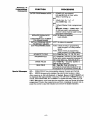
SYSTEM STATUS
REPORT CODES
(’60-’68)
See Examples on programming form.
TROUBLE REPORT CODE
●6O
REPORT
BYPASS
*62
AC LOSS
REPORT
CODE
(See box above.)
*63
LOW BAT REPORT
CODE
(See box above.)
*64
TEST
●65
OPEN/EXIT
ALARM REPORT
CODE, 1st DIGITS
Open Report Code : To enable, enter a code (or O to disable) in the
left-hand box (see box above ‘60).
For expanded or 4+2 re~ottinql 2nd digit= User #.
REPORT
CODE
(See box above.)
*61
CODE
(See box above.)
(See box above.)
Exit Alarm Report Code: To enable, enter a code (or O to disable) in
the right-hand box (see box above *60). If enabled:
ANY ALARM FROM AN EXIT OR INTERIOR ZONE OCCURRING WITHIN TWO
MINUTES AFTER THE END OF THE EXIT DELAY will send a special message
indicatingexit alarm to the centralstation,and a zone indicationand “ExitAlarm”
or “EA is displayedon the console.
IF AN EXIT OR INTERIOR ZONE CONTAINS A FAULT AS THE EXIT DELAY
ENDS, the local bell and console sound continuously.
a) If the subscriber then disarms the system before the ensuing ENTRY delay
ends, no messa e is transmitted to the central station, but a zone indication
and “Canceled AYarm” or “CA” is displayed on the console.
b) /f the system is not disarmedbefore that entry delay ends, a special message
indicating Exit Alarm is sent to the central station and a zone indication and
“Exit Alarm” or” EN is dispiayed on the consoie.
For expanded or 4+2 ret)ortinm a 2nd digit is sent, and is the same as the
2nd digit of the zone aiarm report code programmed in field ●56.
For Contact ID reportinm Event code 374 and the zone number is sent.
There is no restore message for Exit Alarm report.
RESTORE
REPORT CODES
(*69-*75)
*66
AWAY/STAY
CLOSE RPT CODE, 1st DIGITS (See box above.)
To enable, enter a code (or O to disable) in either or both boxes
For expanded or 4+2 reporting, 2nd digit for each= User #.
●67
RF XMTR.
LOW BATTERY
REPORT
CODE
(See box above.)
*68
CANCEL
*69
GROUP RESTORES
FOR TROUBLE,
RF LOW
Enter: O for no (report for each restore),
or: 1 for yes (report after ali zones restored).
Note: “1” not applicable to Contact ID reporting.
*7O
ALARM RESTORE
REPORT
CODE, 1ST DIGIT
For ex~anded or 4+2 reQortin~ a 2nd digit is sent, and is the same as the
2nd digit of the zone alarm report code programmed in field ●56.
*71
TROUBLE
●72
BYPASS
*73
AC RESTORE
*74
LOW BAT RESTORE
*75
RF XMTR.
REPORT
CODE
RESTORE
RESTORE
(See box above.)
REPORT
REPORT
REPORT
CODE
REPORT
LOW BATTERY
-23–
CODE
CODE
BAT,
BYPASS
(See box above.)
(See box above.)
(See box above.)
CODE
RESTORE
(See box above.)
CODE
(See box above.)
OUTPUT AND
SYSTEM SETUP
*8O
OUTPUT
RELAYS
Applicable only if field ●
25 is programmed for a 4229 or 4204,. .othetwise
skip this field,
REFER TO THE OUTPUT RELA Y TABLE FOR THIS FIELD
IN THE PROGFUM4MINGFORM.
(’80-”92)
Relay Basics
Relays can be used to perform many different functions and actions. In this system, each relay must be programmed as to how to act (ACTION), when to activate
(START), and when to deactivate (STOP). Each of these is summarized briefly
below, but described later in detail in the programming procedure for fields ●8O
and *81.
1.
ACTION: The “ACTION” of the relay is how the relay will respond when it is
activated by the “START” programming. There are 4 different choices of
actions:
CLOSE for 2 SECONDS and then reset.
c CLOSE and STAY CLOSED until deactivated by “STOP” programming.
PULSE ON and OFF until deactivated by “STOP” programming.
NO RESPONSE is chosen when the relay is not used.
START: The “START” programming instructs the relay when and under
what conditions to activate. There are 3 parts to be programmed:
●
●
●
2.
●
●
EVENT instructs the relay what condition must occur to the zone(s) programmed into the “ZONE LIST” in order to activate the relay. The
“EVENT” and “ZONE LIST” work together. The 4 different choices for
“EVENT” are listed in the PROGRAMMING section for field ’80.
ZONE LIST is a list of zones selected by the installer in field ●81 .When an
event occurs as assigned by “EVENT” on any zone within that list, the
relay will activate as selected in “ACTION”. In this way, many zones can
be assigned very easily to a single event. For example: You may wish
a relay to activate (perhaps to activate a strobe for a visual indication)
whenever any zone in a group of zones is faulted.
●
3.
ZONE TYPEE3YSTEM OPERATION. Instead of using a “ZONE LIST” and
“EVENT”, a specific zone (response) type or system operation action
can be selected to activate the relay.
“ZONE TYPE” is chosen, any zone of that reIf a specific
sponse type going into alarm, trouble, or fault will cause the relay to activate as selected in “ACTION”.
If a “SYSTEM OPERATION” is chosen, that operation will cause
the relay to activate as selected in “ACTION”.
The different choices for “ZONE TYPE” and “SYSTEM OPERATION”
are listed in the PROGRAMMING section for field ’80.
STOP: The “STOP” programming instructs the relay when and under what
conditions to deactivate. The 2 parts to be programmed are:
“ RESTORE ZONE LIST. If a “RESTORE ZONE LIST” is used, the relay will
deactivate when all the zones in that list restore from a previous fault of
alarm condition, This will occur regardless of what is programmed to
“START” the relay; therefore, a “RESTORE ZONE LIST” would normally only be used when a “ZONE LIST” is used to start the relay.
“ ZONE TYPE/SYSTEM
OPERATION.
Instead of using a “RESTORE
ZONE LIST”, a specific zone (response) type or system operation action can be selected to deactivate the relay.
if a specific
“ZONE TYPE” is chosen, any zone of that response type that restores from a previous alarm, trouble, or fault condition will cause the relay to deactivate.
If a “SYSTEM OPERATION” is chosen, that operation will cause
the relay to deactivate.
The different choices for “ZONE TYPE” and “SYSTEM OPERATION”
are listed in the PROGRAMMING section for field *80,
–24–
-
Output Relay Displays
4
Upon entering field *80, this screen will appear. Enter the Relay Number 01 or 02
for a 4229, or 01, 02, 03, or 04 for a 4204 (or 00 to end these entries). Press the
[$kl kev to advance.
?he data is keyed in and entered for this and the following screens by pressing [+F].To
back up to check an entry,press [#] for each position.Press [~] to go forward again.
Enter Relay No.
(00 = Quit)
Re~y
01
beingprogrammed.
02
AEVZLZT
w-r
00000
This screen discdavs a summarv of the current relav START moarammina (for this
example, relay “02‘has been se(ected). Press the [~] key to adv~nce.
- ‘
This screen displays a summary of the current relay STOP programming. Press
the [%] key to advance.
I
02 Relay Action
No Response
O
I 02 Start Event
02 Start:
I
Event (EV): Enter the event to START the relay. Press the [~] key to advance.
2 = Fault
o = Not used
3 = Trouble
1 = Alarm
Zone List (ZL): If a zone list will be used to START the relay action, enter the
zone list number (to be programmed in field *81): 1, 2, or 3. If not used, enter O.
Press the [x] key to advance.
Zn List
o
No List
Action (A): Enter the desired relay action. Press the [~] key to advance.
2 = Close and Stay Closed
o = Not Used
1 = Close for 2 seconds
3 = Continual Pulses (1 see) On and Off
Zone Type/System
Operation (ZT): If a zone type or system operation will
be used to START the relay action, enter the appropriate two digit code. If not,
Zone Disabled 00 I enter 00. Press the [*] key to advance.
CHOICES FOR ZONE TYPES
00= Not Used
I
02 Start:
Zn Typ
05= Trouble Day/Alarm Night
06= 24 Hr Silent
07= 24 Hr Audible
01 = Entry/Exit
03= Perimeter
04= Interior Follower
CHOICES
20= Arming-Stay
21 =
22=
31 =
32=
**Or
02 Stop:
FOR SYSTEM
08= 24 Hr Aux
09= Fire
10= Interior w/Delay
OPERATION
33= Any Burglary Alarm
34= Code+ #+7 Key Entry
Arming-Away
35= Code+ # + 8 Key Entry
Disarming (Code+ OFF)
36= At Bell Timeout**
End of Exit Time
37= 2 times Bell Timeout**
Start of Entry Time
at Disarming, whichever ocours earlier.
38=
39=
40=
41 =
42=
Chime
Any Fire Alarm
Bypassing
AC Power Failure
System Battery Low
“Restore
of” Zone List (ZL): If a zone list will be used to STOP the relay action, enter the zone list number (to be programmed in field ●81 ): 1, 2, or 3. If not
used, enter O. Press the [~] key to advance.
Zn List
kE!__Q
l==’=
Zone Type/System
Operation (ZT): If a zone type or system operation will
be used to STOP the relay action, enter the appropriate two digit code (see the
I Zone Disabled 00 I “~ choices listed above). If not, enter 00, Press the [W] key to advance.
I
02
AEVZLZf
s-l-r
00000
This screen again displays a summary of the current relay START programming .
Press the [~] key to advance.
I
This screen again displays a summary of the current relay STOP programming.
Press the [x] key to return again to the first screen so that the next relay number
to be programmed can be entered, or enter [0][0] to end relay programming.
Note:
Previous/y entered data can be reviewed by pressing [#] [8] [0]. After the
relay number is chosen, press [#] to go to the next screens. This is a review mode only, and data cannot be changed.
-25-
Example of
Output Relay
Programming
FOR OTHER EXAMPLES
SEE THE TABLE
ON PAGE 44
Let us light an indicator
when any one of 3 specific
zones are
faulted or when any 24 hour aux. zone is disturbed.
We want to
turn off the indicator
manually without affecting
the arming status
of the system.
In field *8O we choose Output Relay 01 and program the Action (A) to be “2”
(Close and stay closed). The Event we are looking for to staff the relay action is a
fault, so we will program “2” in (EV). We will use Zone List 1 for the 3 specific
zones, so will program “1” in (ZL),(and will program these 3 zones in field *8I’s
Zone List 1).
The second condition for turning on the indicator is triggering a 24 hour aux. zone
(Zone Type 08), so we will program (ZT) as “08”.
To stop relay action and turn off the indicator, we do not want to use a restore of
any zone, so we will program a “O”for the “Restore of” Zone List (ZL). To choose a
manual entry of User Code+ [#] + [7] to turn it off, we will program (Zl_) as “34”.
If no other relay is to be programmed we go to field ●81 and program the 3 specific
zones in Zone List 1.
’81
ZONE
LISTS
FOR
OUTPUT
RELAYS
Applicable only if field *25 is programmed for a 4229 or 4204...otherwise
skip this field.
Zone List Disnlaw
Upon entering field “81, this screen will appear. Enter the Zone List Number 01,
02, or 03 to program (or 00 to end these entries). Press the [~] key to advance.
In the following displays, zone list 03 has been selected for programming.
&
~ Zone
List selected.
Enter each zone number to add to the zone list by first entering the zone number,
then the [~] key (ex., 01X, 02~, 03~). After all desired zones are entered, enter
00
00 to advance.
&
To delete the zone list, enter 1 (Yes). All zones in the zone list will be deleted
automatically and programming will return to the first screen.
To save the zone list, enter O (No) to advance.
!!EYEl
P!!zzlscreen
EE!l
0 =‘0
1 = ‘es
0
To save the entire zone list, enter O (No) and programming will return to the first
0 =‘0
1 = ‘es
0
00
To delete a zone or zones in a zone list enter 1 (Yes) to advance.
Enter each zone to be deleted from the list, followed by the [~] key. After all
zones to be deleted are entered, enter 00 to return to the first screen so that
another list can be programmed, if desired. .
NO tes:
●
●
●
*82
Any list may include any or all of the system’s zone numbers.
A zone list can be assigned to more than one output relay.
If you only want to review what has been programmed previously,
enter [#][8][1 ]. The review can be advanced by using the [#] key.
When finished, enter [0][0] to quit. No programmed values can be
disturbed in this mode.
CUSTOM
ALPHA
EDITING
(Also entered from field
●56)
~ See ALPHA DESCRIPTION ENTRIES section on page 29: [
DOWNLOAD
INFORMATION
(*94,
*95]
*83
ADD/DELETE
5800 RF INPUT IDs (Serial
See procedure in last paragraph of field *56.
Nos
& Sensor
Pts)
●92
MAXIMUM
NUMBER
OF REPORTS
PER ARMED PERIOD
Enter: Ofor a maximum of 10 total alarm plus alarm restore reports,
or: 1 for an unlimited number.
●94
DOWNLOAD
PHONE
NUMBER
Enter up to 12 digits, O-9, #+11 for ‘~’, #+12 for ‘#’, #+13 for a pause. Do
not fill unused spaces. If fewer than 12 digits entered, end field by
entering X (and press next field number). To clear field, press X94X,
’95
RING DETECTION
COUNT FOR DOWNLOADING
Enter number of rings before control picks up phone line (or O or 15).
O = disable station initiated download
1-14 = #of rings
15=
answering machine defeat
–26–
*96
INITIALIZE
DOWNLOAD
ID AND SUBSCRIBER
FOR DOWNLOADING
(No data entry required, loads defaults)
*97
SET ALL PROGRAM
(No data entry required)
FIELDS
TO
DEFAULT
ACCT.
No.
VALUES
Press X98 or X99 if exiting programming,
or next Field No. if continuing.
TO EXIT
PROGRAMMING
MODE
(*98 or *99)
*98
EXITS PROGRAMMING
MODE and prevents re-entry by :
Master Code + CODE + O
, ~~
EXITS PROGRAMMING
MODE and abvs
Master Code + CODE + O
or by:
Power-up + X + #.
ALPHA DESCRIPTION
re-entry by:
ENTRIES
See the ALPHA FIXED DICTIONARY and CHARACTER CHART on page 29.
If using a 4285 Voice Module, selection from the group of words in boldface type is suggested.
The voice module will not provide annunciation of the other words.
Assigning
Zone Descriptors
Entering
Zone Descriptors
(in fieid *56 or *82)
The Alpha Console used with the Atfemco vla30+ can have a user-friendly English language descriptiordlocation of all protection zones, keypad panics, and RF
receiver supervision faults programmed into the system. Each description can be
composed of a combination of words (up to a maximum of 3) selected from a vocabulary of 244 words stored in memory (see page 29). In addition, up to 5 installer-defined words can be added to those already in memory. Thus, when an
alarm or trouble occurs in a zone, an appropriate description for that zone’s location will be displayed at the console.
Note: Alpha Descriptor entry can be done locally at the Alpha Console or remotely using a 4130PC Downloader. The Alpha Console procedure is
described below.
1.
2.
The descriptor can be entered when the zone is being defined in field ●56 or
it can be entered later, in field ●82.
Key [+K][O][l] to begin entering the description for zone 1 (key [x][O][2] for
zone 2, [-X][O][3]for zone 3, etc.). /f nothing was entered previous/y, the following will be displayed:
3.
~
Note that the first letter of the alphabet appears after the zone number, and
that the zone number is automatically included with the description. /f there
a/ready is a description for the zone, the description will appear (with no cursor, since this is a display mode). /fit is desired to enter or change a description, key in [~] + Zone Number again. A flashing cursor will now appear.
One of two methods
of entering
the words can now be used
(assume, for examp/e that the desired description for zone 1 is BACK DOOR):
a) Press [#] followed
by the 3 digit number of the first word
from the fixed dictionary
shown on page 29 (e.g., [0][1][3] for
BACK). Press [6] in order to save the word and proceed, or...
-27-
b)
IN
STEPS
3-5,
THE CONSOLE
KEYS
PERFORM
THE FOLLOWING
FUNCTIONS
[3]
Advances through alphabet
and actual words in alphabetical order.
[1]
Moves backward through
alphabet and actual words
in alphabetical order.
[6]
[8]
4.
Select the first letter of the desired description
(note that “A”
is already displayed). Press key [3] repeatedly to advance through the alphabet (e.g., to “B”), or key [1] to go backward. Then press [6] to display
the first available word beginning with the desired letter (e.g., BABY).
Next, press [3] repeatedly to move forward, or [1] to move backward, until
the desired word is displayed (e.g., BACK). Then press [6] to accept the
word and toggle back to the alphabet list.
For selection of the next word (e.g., DOOR), repeat steps 3a or 3b. For 3b,
~
press key [3] until the first letter of the next word appears (e.g., “D”). Then
press [6] to display the first available word beginning with that letter (e.g.
Toggles between alphabet
and actual word list; used to
accept entries.
5.
Saves the zone description
in the system’smemory.
1
DAUGHTERS).Press [3] repeatedly until the desired word (e.g., DOOR) appears. To accept the word, press [6], which toggles back to the alphabet list.
When all desired words have been entered, press [8] to store the description
in memory.
/n fie/d *56, the next zone number in sequence will now be displayed for
comp/ete zone information entry.
/n fie/d ●
82, enter ~][N][N], where NN is the next zone that you want to review
or for which you want to program a descriptor. To modify the descriptor, enter
[X][N][N] again. To exit this mode, press [*][OJIO].
Adding Custom Words
(wiii not be annunciated
by 428S Voice Moduie)
Up to five installer-defined words can be added to the built-in vocabulary. Each of
the five “words” can actually consist of a “word string” of severs/ words, but no
more than ten character can be used for each word or word string.
1. Select CUSTOM WORD mode when the question arises.
2. Key the number ([1 ]–[5]) of the custom word or word string to be created (for
example, if you are creating the fimt custom word or word-string, enter [1], for
the second, enter [2], etc.). A cursor will now appear at the beginning of the
second line.
One of two methods of entering the custom word’s characters
ii.
IN STEPS
3-6,
can now be used (refer to the CHARACTER LIST of letters, numbers, and
THE CONSOLE
KEYS
svmbo/s on the next Daae):
PERFORM
-,
THE FOLLOWING FuNcTloNs I /mDortan~
Custom words must begin with an alphabetic character. If a number
[3]
Advances through alphabet, symbols, and numbers.
[1] Moves backward through
alphabet,
numbers
and
symbols.
[6]
Selects
desired
letter;
moves cursor one space to
right.
[4]
Moves cursor one space to
left.
[7]
Inserts a space at the cursor location, erasing any
character located there.
[8]
Saves the new word in the
svstem’s memory.
or symbol is used as th~ first character, the word will not be saved.
a) Press the [#] key, foiiowed
by the two digit entry for the
first ietter you wouid iike to dispiay (e.g., [6][5] for “A”), or...
b) Use the [3] key to advance
through
the iist of symbols,
numbers, and ietters. Use the [1] key to move back through the list.
4. When you have reached the desired character, press [6] to select it. The cursor will then move to the right, in position for the next character.
5. Repeat steps 3 and 4 to create the desired word(s). Note that the [4] key can
be used to move the cursor to the left, if necessary, and that key [7] can be
used to enter a blank (or erase an existing character). Remember, no word or
word-string can exceed 10 characters.
6. Press the [8] key to save the custom word(s) and return to the “CUSTOM ?“
display. Repeat steps 2-5 for other custom words to be entered. To change a
custom word. iust overwrite it. If no more are to be entered now. Dress ~01to
return to the Descriptor entry. The custom word(s) will be automatically a%led
to the built-in vocabulary.
When zone descriptors are being entered as described in step 3a of the Entering
Zone Descriptors section, the custom word numbers are 250 to 254 for words 1
to 5 respectively. When being entered as described in step 3b of that section,
each word will be found at the end of the group of words that begin with the same
letter as it does.
-28–
—
ALPHA FIXED DICTIONARY
(For
000
001
●
002
003
004
005
006
007
006
009
010
011
●
●
●
●
(Word Space)
AIR
ALARM
ALCOVE
ALLEY
AMBUSH
AREA
APARTMENT
ART
ATTIC
AUDIO
AUXILIARY
054
●
●
●
●
●
●
012
013
014
015
016
017
018
019
020
021
022
023
024
025
026
027
BABY
BACK
BAR
BARN
BASEMENT
BATHROOM
BED
BEDROOM
BELL
BLOWER
BOILER
BOTTOM
BOX
BREAK
BUILDING
BURNER
028
028
030
031
032
033
034
035
036
037
038
039
040
041
042
043
044
045
046
047
CABINET
CALL
CAMERA
CAR
CASE
CASH
Cclv
CEILING
CELLAR
CENTRAL
CIRCUIT
CLIP
CLOSED
COIN
COLD
COATROOM
COLLECTION
COMBUSTION
COMPUTER
CONTACT
048
049
050
051
052
053
DAUGHTERS
DELAYED
DEN
DESK
DETECTOR
DINING
●
●
●
●
●
●
●
●
●
●
●
●
●
●
●
●
●
Not e:
●
●
Entering
DISCRIMINATOR
DISPLAY
DOCK
056
057
058
059
060
061
062
063
064
DOWN
DOWNSTAIRS
DRAWER
DRIVEWAY
DRUG
DUCT
065
066
067
068
069
070
071
072
EAST
ELECTRIC
EMERGENCY
ENTRY
EQUIPMENT
EXECUTIVE
EXIT
EXTERIOR
●
●
●
●
●
●
●
●
●
●
073
074
075
076
077
078
079
080
081
082
083
084
085
086
087
088
089
090
091
092
093
094
●
DOOR
DORMER
●
●
●
●
●
●
●
FACTORY
FAILURE
FAMILY
FATHERS
FENCE
FILE
FIRE
FLOOR
FLow
FOIL
FOYER
FREEZER
●
FRONT
FUR
FURNACE
●
GALLERY
GARAGE
GAS
GATE
GLASS
●
●
●
●
●
●
●
106
107
108
LEVEL
LIBRARY
LIGHT
LINE
LIQUOR
LIVING
LOADING
LOCK
LOOP
LOW
LOWER
119
120
121
122
123
124
125
126
127
128
129
130
131
132
133
MACHINE
MAGNETIC
MAIDS
MAIN
MASTER
MAT
MEDICAL
MEDICINE
MICROWAVE
MONEY
MONITOR
MOTHERS
MOTION
MOTOR
tA13
134
135
NORTH
NURSERY
136
137
138
139
140
141
142
OFFICE
OIL
OPEN
OPENING
OUTSIDE
OVERFLOW
OVERHEAD
143
144
145
146
147
148
149
150
151
152
153
PAINTING
PANIC
PASSIVE
PATIO
PERIMETER
PHONE
PHOTO
POINT
POLICE
POOL
POWER
154
QUAD
#
$
Yo
&
(
●
●
095
096
087
098
099
HALL
HEAT
HIGH
HOLDUP
HOUSE
100
101
102
103
INFRARED
INSIDE
INTERIOR
INTRUSION
104
JEWELRY
●
●
●
ls - RADlo
156 REAR
157 RECREATION
156 REFRIG
159 REFRIGERATION
160 1+
161 RIGHT
162 ROOM
163 ROOF
●
●
164
165
166
c 167
●
168
169
●
170
171
172
●
173
174
175
●
176
177
●
178
●
179
180
181
●
182
163
164
●
185
166
167
188
169
190
191
192
193
SAFE
SCREEN
SENSOR
SERVICE
SHED
SHOCK
SHOP
SHoRT
SHOW
SIDE
SKYLIGHT
SLIDING
SMOKE
SONIC
SONS
SOUTH
SPRINKLER
STAMP
STATION
STEREO
STORE
STORAGE
STORY
STRESS
STRIKE
SUMP
SUPERVISED
SUPERVISION
SWIMMING
SWITCH
194
195
186
197
198
199
200
201
202
203
TAMPER
TAPE
TELCO
TELEPHONE
TELLER
TEhIPERAN~
THERMOSTAT
TOOL
TRANSMllTER
TRAP
●
●
204
205
●
206
s 207
●
●
208
●
●
209
210
211
212
VALVE
VAULT
VIBRATION
VOLTAGE
213
214
215
216
217
218
219
220
221
WALL
WAREHOUSE
WASH
WEST
WINDOW
WINE
WING
WIRELESS
WORK
222
XMlllER
223
YARD
224
225
ZONE (No.)
ZONE
226
227
228
229
230
231
232
233
234
235
236
237
238
239
240
241
242
243
244
0
1
1ST
2
2ND
3
3RD
4
4TH
5
51H
6
6TH
7
7TH
8
8TH
9
8TH
250
Custom Word #1
251
Custom Word #2
252
Custom Word #3
ULTRA
UP
UPPER
253
Custom Word #4
UPSTAIRS
UTILITY
254
Custom Word #5
Bulleted (.) words in boldface tv~e are those that are also available for use bv the 4285 Voice Module.
If using a’voice module, and wo~ds other than these are selected for alpha des~riptors, the voice module
will not provide annunciation of those words.
\space)
,,
LAUNDRY
LEFT
109
110
111
112
113
114
115
116
117
118
CHARACTER
32
33
34
35
36
37
38
39
40
Descriptors)
GUEST
●
●
Zone
KITCHEN
●
●
●
105
41
)
50
2
42
43+
44,
45
46
47
48
49
*
51
52
53
54
55
56
57
58
3
4
5
6
7
8
9
:
;
0
1
(ASCII) CHART
(For Adding Custom Words)
68 D
59 ;
60
61
62
63
64
65
66
67
<
=
>
?
@
A
B
C
-29–
69
70
71
72
73
74
75
76
E
F
G
H
I
J
K
L
77
78
79
80
81
82
83
84
85
M
N
0
P
Q
R
S
T
U
86
87
88
89
90
v
W
x
Y
z
Report Code Formats
The Report
Codes
for Alarm,
System
Status,
and Restore
for
Zones shown in program fields ●56-*75 can be selected in field ●46
to report to the central station in any of the following formats:
27) is enabled, all dialer and
Note:
If OUTPUT TO LONG RANGE RADIO (field ●
long range radio reports will be sent in Contact ID format (see next page),
regardless of the selection made in field ●46.
The 3+1 and 4+1 Standard formats comprise a 3 (or 4) digit subscriber
number and a single digit report code (e.g. Alarm, Trouble, Restore, Open,
Close).
The 3+1 and 4+1 Expanded formats comprise a 3 (or 4) digit subscriber
number, and a single digit report code, followed by a second line where the report
code is repeated 3 (or 4) times and followed by another number (normally the
zone number) or user ID related to that report.
The 4+2 formats comprise either a 4 digit subscriber number and two digit
report code, or a 4 digit subscriber
number and single digit report code,
immediately followed by the zone number (normally) or user ID.
Report
3+1,
4+1
Standard
Alarm
SSS(S) A
3+1,
4+1
Expanded
4+2
SSS(S) A
Ssss Az
AAA(A) Z
Trouble
SSS(S) T
SSS(S) T
Trr(l-) t
SSS(S) B
BBB(B) b
SSS(S) E
EEE(E) ~
SSSS Tt
Bypass
SSS(S) B
AC LOSS
SSS(S) E
Low Batt
SSS(S) L
SSS(S) L
LLL(L) LB
SSSS LLB
Open
Sss(s)o
Ssss Ou
Close
Sss(s)c
Sss(s) o
Ooo(o) u
Sss(s)c
ccc(c) u
Test
SSS(S) G
SSS(S) G
::$~G~
SSSS Gg
Restore
Alarm
AC Restore
SSS(S) R
LoBat Res.
SSSS Bb
SSSS E~
Ssss Cu
Ssss Rz
SSS(S) RA
RRR(R) Z
SSS(S) RA
RARARA(RA)~
SSSSRA ~
SSS(S) RL
SSS(S) RL
SSSS RLLB
Trouble Res.
SSS(S) RT
RLRLRL(RL)LB
SSS(S) RT
RTRTRT (RT)t
SSSS RTt
Bypass Res.
SSS(S) RB
SSS(S) RB
RBRBRB (RB)b
SSSS RBb
!!!!hMa
SSS or
Ssss =
A=
z=
Tt =
Bb =
EAc .
LLB .
o=
Subscriber ID
Alarm Code-lst digit
Typically Zone Number*-2nd digit
Trouble Code (1st &2nd digits)
Bypass Code (1st & 2nd digits)
AC Loss Code (Ist & 2nd digits)
Low Battery Code(l st & 2nd digits)
Open Code-1 st Digit
*Zone
numbers
foc
[+c]&[#], or [B] = 7
Duress. 8
Tamper = 9
c=
u=
Gg =
R=
RTt =
RBb =
RAAc =
RLLB =
Close Code-1 st Digit
User Number (1st & 2nd digits)
Test Code (1st & 2nd digits)
Restore Code (Alarm)l st & 2nd digits
Restore Code (Trbl)lst & 2nd digits
Restore Code (Byps)lst & 2nd digits
Restore Code (AC)l st & 2nd digits
Restore Code (Bat)l st & 2nd digits
[1]+ [~], or [A ] = 95
[3] + [#], or [C] =96
(continued)
-30-
~
The Ademco Contact ID Reporting format comprises a 4 digit subscriber
number, 1 digit event qualifier (“new” or “restore”), 3 digitwent code, 2 digit
“00”, and 3 digit zone, contact ID, user, or system status number. ..
. :,,
.“.
Ademco Contact ID Reporting takes the following format:
CCCC Q EEE GG 222
whenxCCCC = Customer(subscriber)ID
Q= Event qualifier, where: E = new event, and R = restore
EEE =
GG =
222 =
Event code (3 hexadecimal digits, defined in the table below)
Always 00.
Zone/contact ID number reporting the alarm, or user number for
open/close reports. System status messages (AC Loss, Walk
Test, etc.) contain zeroes in the 222 location.
TABLE OF CONTACT ID EVENT CODES
I Code
~.
.
llU
121
122
I 123
131
132
134
135
I 150
I Definition
Fire Alarm
Duress
OIle
“’-ret Panic
I Audible Panic
Perimeter Burglary
Interior Burglary
Entry/Exit Burglary
Day/Night Burglary
I 24 Hour Auxiliary
EL
Code
1
1
I
-.
.,-.
I Definition
I
ImE%
AI ‘h’e (global)
If Supervision - RF
r Tamper
..- I mnsmitier Low Battery
IC By (JSer
1%-K
I
----
.rln,-.l
I
I
Il
\lLnlall
k 407
~ 408
441
570
601
602
–31–
k.,
I I-qr
s:-----. . . ..t -MJWI
IIU~
Remote AtiDlsal
III tnm
d)
1Quick Arm
Armed STAY
Bypass
Test - Manually Triggered
Periodic Test
I
.
Oeneral Information
The Adefr?co vla30+ can be remotely programmed from an IBM compatible Personal Computer (PC), a Hayes Modem, and Ademco’s V-LINK@ Software (see
below).
Such programming is protected against compromise by someone attempting to
defeat the system, by using multi-levels of security protection:
1. Security
Code Handshake:
An 8-digit download ID code must be
matched between the control and the downloader.
The installer or subscriber initi2. Site Initiated Remote Programming:
ates the callback from the subscriber premises (by pressing MASTER CODE
+ # + 1) while disarmed. All parameters can then be downloaded via the
phone lines using a personal computer.
Remote Programming:
The operator calls the site
3. Station Initiated
from your office to initiate the downioad call. The control hangs up and then
calls back the PC via the preprogrammed telephone number. The unit can
then be uploaded, downloaded, or controlled from your office .
4. Data Encryption:
Data passed between the PC and the control is encrypted for security so that it is very difficult for a foreign device tapped into
the phone line to take over communication and substitute system compromising information.
Equipment
At the premises:
. Ademco via30+ and console.
At the instaiier’s
office/home:
An IBM PC compatible computer.
. fWrer: A Hayes brand Smartmodem 1200 [Level 1.2 or higher external
or Level 1.1 or higher (with 4 position DiP switch) internal style],
or: A Hayes brand Optima 24 Plus FAX96 Modem (set Aux Modem
Command to: )(&D2&C l&QQ).
Required
_
●
.
.
Programming
A No.4130PC Downloading Software Diskette (Rev. 3.0, or higher).
Appropriate interconnecting cables.
The downloading system can perform many functions when in communication
with the control unit. Besides uploading and downloading, the status of the system can be observed and various commands can be initiated, as follows:
Arm the System in the Away Mode; Disarm the System.
Bypass a Zone.
Force the System to Accept a New Program Download.
Shut Down Communication (dialer) Functions (non-payment of monitoring
fees in an owned system).
Shut Down all Security System Functions (non-payment for a leased system).
inhibit Local Keypad Programming (prevents account takeover).
Command the System to Upload a Copy of its Resident Program to the office.
Read: Armina Status, AC Power Status, Lists of Faulted Zones, Bvt)assed
Zones, Zone~Currently in Alarm, Zones Currently in Trouble, and RF ‘Sensors
with Low Battery Conditions.
/Votes: After the control and the PC have established valid communication, each
console on the system will become inactive and will display “CC” or “MODEM
COMM.”. The controi, however, will still be scanning its zones and looking for
alarms. If an aiarm does occur, after communication is broken off, alarms are
sounded and the proper dialer reports are sent to the central station. The consoles will become active after the download communication is terminated. The
detailed operation of the download functions is covered in the installation instructions for the 4130PC Downloading Software Diskette.
●
●
●
●
●
●
●
●
Remote Programming
Advisory Notes
.
Alarm and trouble reporting may be deiayed during the time that the system
and the Downloader are linked to each other following a valid exchange of
codes, but the proper message will get through to the Central Station after the
iink is broken.
(continued)
–32-
w
●
Keypad entries are ignored during the time intetval stated above.
Q A copy of the program downloaded may be produced from the IBM PC
compatible computer, using the product’s internal report generator, when an
optional printer is connected (consult your PC manual for proper printer and
connections).
Program Upload Time-One
minute fifteen seconds for a complete program.
s Program Download Tim*Depends
on changes. Average time, one minute.
●
SECURITY CODES
Master
Code
User Codes
The installer programs the 4-digit Master Code initially as part of the programming
procedure (see PROGRAiWWfVG THE SYSTEA$ The factory default Master code
is “4111”.
The Master code can permit re-entry into the programming mode and also, in
normal operation mode, is used to enter the user codes, which also allow access
to the normal functions of the system.
See the PROGRAMMING section for information on exiting the programming
mode via fields *98 or *99.
In normal operation mode, the Master security code can be used to assign
up to six secondary security codes. It can also be used to remove secondary
codes from the system (individually).
To assign
(or change)
a Secondary
security
Master Code + [CODE] key+ User # (2, 3,4,5,6,
code, enter:
or 7) + desired Secondary Code
The system will emit a single beep when each secondary code has been successfully entered.
To delete a Secondary
security code, enter:
Master Code + [CODE] key+ User # (2,3,4,5,6,
or 7)
Notes:
. All Master and Secondary security codes permit access to the system for arming, disarming, etc.
If a secondary code is inadvertently repeated for different users, or one user’s
code is another’s duress code (4th digit increased by 1), the lower user number
will take priority.
c Opening and closing reports are sent for the Master code as No. 1. User codes
are sent as Nos. 2 through 7 respectively.
●
KEYPAD FUNCTIONS
Qeneral Information
Note that if QUICK ARM is enabled (field *21), the [#] key can be pressed instead
of entering the security code, for any of the arming procedures (Away, Stay, instant, Maximum, etc.). The security code is a/ways required, however, when disarming the system.
The keypad allows the user to arm and disarm the system, and perform other system functions, such as bypassing zones, and display zone descriptors. Zone and
system conditions (alarm, trouble, bypass) are displayed in the Display Window.
When an alarm occurs, console sounding and external sounding will occur, and
the zone(s) in alarm will be displayed on the console. Pressing any key will silence
the console sounder for 10 seconds. Disarming the system will silence both console and external sounders. When the system is disarmed, any zones that were
in an alarm condition during the armed period will be displayed (memory of alarm).
To clear this display, simply repeat the disarm sequence (enter the security code
and press the OFF key) twice.
The consoles also feature chime annunciation, and 3 panic keys, or key pairs, (for
silent, audible, fire, or personal emergency alarms) which can notify the central
station of an alarm condition, if that service is connected.
-33–
Arming
Functions
The following is a brief list of system commands. For detailed information
concerning system functions, refer to the User’s Manual.
Disarmed,
Not Ready
Before arming, the system must be in the READY
condition (all zones must be intact). If the “NOT
READY” message appears, press the READY [~]
key to display faulted zones.
Arming Away
Enter code + AWAY [2].
Arming Stay
Enter code + STAY [3].
Arming Instant
Enter code + INSTANT ~.
Arming Maximum
Enter code + MAXIMUM [4].
Enter code + OFF [1].
Disarming
-,
Enter code + BYPASS [6]+ zone number(s~.
- ‘“
Bypassing
Zones
Forced (Quick) Bypass
(/f enab/ed) To bypass all faulted zones at once,
use “Forced Bypass’ method:
Enter code + BYPASS (then stop).
Enter code + CHIME [9].
Chime Mode
To turn chime mode off, enter code+ CHIME again.
-
SUMMARY
OF ARMING MODES
Features for Each Arming Mode
Mode
AWAY
STAY
INSTANT
MAXIMUM
Panic Keys
Perimeter
Armed
Yes
Yes
Yes
Yes
Interior
Armed
Yes
No
No
Yes
There are three panic key pairs and (on some consoles) lettered keys(shown below) that, if programmed, can be used to manually initiate alarms and send a reporl
to the central station. Each can be individually programmed for 24 Hour Silent,
Audible, Personal or Fire Emergency responses. The panic function is activated
when both keys of the appropriate key pair are pressed at the same time, or the
appropriate lettered key is pressed for at least 2 seconds.
The panic functions are identified by the system as follows:
KEYS
Displayed
95
[x] & [#], or [B]
07
[3]& [#],or [C]
96
●
●
W’
as Zone
[1] & [*], or [A]
Notes:
Keys [A], [B], [C] are not on all consoles.
Key [D], if present, is not active here.
IMPORTANT:
Relay Outputs
(if used)
Entry
Delay
Yes
Yes
No
No
Exit
Delay
Yes
Yes
Yes
Yes
For the Silent Panic function to be of practical value,
the system must be connected to a centra/ station.
“
If relay outputs are provided (via a 4204 or 4229), two keypad entries available to
the user are included among the system operation choices that may be
programmed. They can manually activate or deactivate the relay(s) for starting or
stopping some action, such as turning lights on or off, etc.
These entries are: Security Code + [#] + [7]
and Security Code + [#] + [8]
Note: Whichever entry is used to starthtop the action cannot also be used
to stop/start it. The opposite action must either be performed by the
other keypad entry or by some other event or operation offered in the
programming section.
For some examples, see pages 26 and 45.
(continued)
-34-
e
Exit Alarm
Displays
(if programmed]
A display of “CANCELED
ALARM” or “CA” and a zone indication
will appear if an exit or interior zone contained a fault during closing at the time
the exit delay ended (e.g., exit door left open), but the system was disarmed
during the irmnediate/y fo//owing entry delay time. The alarm sounder and
keypad sound continuously, but stop when the system is disarmed. No
message will be transmitted to the central station.
c A display of “EXIT ALARM” or “EA” and a zone indication
will
appear if an exit or interior zone contained a fault during closing at the time the
exit delay ended, but the system was NOT disarmed during the irnmecfiate/y
fo//owing entry de/ay time. The alarm sounder and keypad sound continuously
until the system is disarmed (or timeout occurs). An “exit alarm” message is sent
to the central station.
The “EXIT ALARM” display, etc. will also result if an alarm from an exit or
interior zone occurs within two minutes after the end of an exit delay.
In any of the above cases, a second OFF sequence (code plus OFF key) will clear
the display.
●
●
TROUBLE
General
CONDITIONS
Information
‘Check” and
“Battery” Displays
The word “CHECK on the Keypad’s display, accompanied by a rapid “beeping”
at the Keypad, indicates that there is a trouble condition in the system. The audible warning sound can be silenced by pressing any key. Instruct users to call for
service immediately upon seeing any of the following messages.
A display of “CHECK” and one or more zone numbers indicates
a problem exists with the displayed zone(s) and requires attention.
●
●
●
●
Power Failure
that
When the problem has been corrected, the display can be cleared by entering
the OFF sequence (code plus OFF key) twice.
If there are wireless sensors in the system, the CHECK condition may
also be caused by some change in the environment that prevents the receiver
from hearing a particular sensor.
A display of “BAT” with no zone number indicates that the system’s
main standby battery is weak.
A display of “BAT” with a zone number and a once per minute
“beeping” at the keypad indicates that a low battery condition exists in the
wireless sensor displayed (zone “00” indicates a wireless keypad). If the battery
is not replaced within 30 days, a CHECK display may occur.
Note: Some wireless sensors contain a non-replaceable long-life battery
which requires replacement of the entire unit at the end of battery life
(e.g., Nos. 5802, 5802CP, 5803).
●
●
If there is no keypad display at all, and the POWER indicator (if
present) is not lit, operating power for the system has stopped and the system is inoperative.
If the message
POWER indicator
power only.
and the
“AC LOSS” or “NO AC” is displayed,
(if present) is off, the keypad is operating on battery
. If the battery standby capacity is used up during a prolonged
AC
power outage, the control’s auxiliary power will shut down to minimize deep
discharge of the battery.
Other Displays
(Fixed Word Keypads)
dl
If this remains displayed for more than 1 minute, the system is disabled.
CC
The system is in communication with the central station for change of function or status verification.
FC
OC
A communication failure has occurred.
The keypad is not receiving signals from the control panel and sees an
open circuit.
-35-
Procedure
After installation is completed, the Security System should be carefully tested.
1. With the System in the disarmed state, check that all zones are intact. If NOT
READY is displayed, press the [~] key to display the faulted zone(s). Restore faulted zone(s) if necessary, so that READY is displayed. Fault and restore every sensor individually to assure that it is being monitored by the
system.
2. Enter the security code and press the TEST key. The outside sounder
will sound for 1 second. The console should sound 3 beeps each time a contact is faulted. A test report should be transmitted (if programmed) to the Central Station immediately. [f the backup battery is discharged or missing, the
sounder may not turn on and a LOW BAITERY report will be transmitted with
a TEST report. The console will beep once per minute as a reminder that the
system is in the Test Mode.
To turn off the test mode enter the security code and press the OFF key.
Afote: For 5800 systems, triggering a zone set to Arm Away, Arm Stay, or
Disarm will take the system out of TEST and cause that action.
Alarm messages will be sent to the central station during the folthat tests will be in
Iowing tests 3 and 4. Notify them in advance
progress.
3. Arm the system and fault one or more zones. After 15 seconds (if optional dialer delay is selected), silence alarm sounder(s) by entering the code and
pressing OFF. Check Entry/Exit delay zones.
4. Check the keypad-initiated alarms that are in the system by pressing the
Panic key pairs. If the system has been programmed for audible emergency,
the console will emit a steady alarm sound, and ALARM and zone number will be displayed. Silence the alarm by entering the security code and
pressing OFF.
If the system has been programmed for silent emergency, there will be no
audible alarms or displays, but a report will be sent to the central station.
5. If output relays have been installed, test their programmed action.
Notify the central station when all tests are finished, and verify results with
6
them.
7. To test the wireless part of the system and the RF Receiver, 3 additional test
modes are available:’
a. HOUSE ID SNIFFER MODE (not app/icab/e to, or necessary with,
5800 RF system): By pressing Master code + # + 2, a house code
“sniffer” mode is enabled. The console will display the house code of any
RF transmission it receives. In this way, you can check that you are not
using the same house code as any nearby system (suggested test
period: approx. 2 hrs). This mode can be exited by keying the Master
code + OFF.
SNIFFER
MODE: Pressing Master code + # + 3
b. TRANSMITTER
initiates a procedure to check that all transmitters have been properly programmed. The console will display all zone numbers of wireless units programmed into the system. As the system receives a signal from each of
the transmitters, the zone number of that transmitter will disappear from
the display. The transmitter codes may be checked upon installation, or in
an installed system. All the wireless addresses should disappear after
about 1-1/2 hours. This mode can be exited by keying Master code +
OFF. (Note With a 5800 RF system, a transmitter not learned will not
turn off its zone number.)
c. GO/NO GO TEST MODE: By pressing Master code + # + 4, a
mode similar to the user test mode (code + TEST) is entered, but the
wireless receiver gain is reduced. Checking in this mode assists in
determining good mounting locations for the transmitters when the
system is being installed and verifies that the RF transmission has
sufficient signal amplitude margin for the installed system. Exit the mode
by entering Master code + OFF.
THE TEST MODE WILL BE AUTOMATICALLY TERMINATED AFTER 4 HOURS
IF THE INSTALLER OR USER DOES NOT MANUALLY TERMINATE IT.
This insures that Fire and Panic zones will not remain disabled.
-36–
_
e
TROUBLESHOOTING
GUIDE
SYSTEM
SYMPTOM
1.
2.
1.
t.
!.
POSSIBLE
Transmitted slgnel not received at 4281/5881.
REMEDY
la
Check or change transmitter’sbattery.
Check Ademco W30+’S AC power.
1b.
Transmitter and 4281 not set to same
house code.
1b.
Check code switches inside transmitter.
Must match with RF House Code programmed in Ademco v/e30+.
1c.
5827 not being received by 5881.
1c.
1d.
Strong local RF interference (frequent or
prolonged lighting of indicator LED on
4281 /5881 circuit board.. ..occasional
random flicker is ok).
1d.
Houea code for 5827 must be programmed
into Ademco via30+.
Relocate 4281.
1e.
Transmitter located too far from 4281/5881.
1e.
Move transmitter or 4281 /5881.
1f.
Metal shielding between transmitter and
4281/5881 .
1f.
Check for large metal obstructions, then
relocate transmitter if necessary.
1g.
Transmitter malfunctioning.
1g.
Verify by activating 4281/5881 with another, similar transmitter. If O.K. now,
return defective transmitter.
1h.
4281/5881
1h.
Verify by making sure other transmitters
cannot activate 4281/588 1. If defective,
repiace and return original 4281/5881.
1i.
Transmitter number (zone) not programmed.
li.
Verify programming.
malfunctioning.
Used).
2a, Set ZT to a vaiidactivezone type in field
●56.
2b.
Transmitter battery not installed.
2b.
Install proper battery.
2c.
5700 System transmitte~s DIP switch not
set properly (house ID and transmitter ID).
2c.
Check end set the DIP switch.
2d.
5800 System transmitter not “teamed” in
system.
2d.
“Learn’ unit in field *56 or ●83.
2e.
With 5700 System, no response at all to
any transmitter.
2e.
Check 4281 receiver. It must be
Rev. D or later and have ‘N5334~
marked
on the large integrated circuit near the connector.
System battery is low or mi=ing.
Transmitter zone number
appears during Transmit-
2a. Transmitterzone type (ZT) is set to 00 (Not
ter Sniffer
not clear.
mode!
Low Battery
coneole.
Periodic
console.
but
message
besp(s)
does
on
from
With 5800 System, no response to a transmitter
in
normai
operation,
although
zone number
clears during
Transmitter
6.
CAUSE
1a. Transmitteror 4281/5881 not properlypowered.
Nujsance
aiarm.
Sniffer
or phantom
mode.
3s.
“Batvalone.
3a.
3b.
“Bet”+ “00”.
3b.
Remote RF keypad battery is low.
3c.
“Bet”+ ‘nn=.
3c.
Transmitter for zone nn has a low battery.
4a.
System is in TEST mode.
4a.
Entar “Code”+ OFF to exit TEST mode.
4b.
A transmitter low battery has occurred and
is displayed.
4b.
Enter ‘Code”+ OFF and repiace the
battery.
4c.
A supervision CHECK has occurred.
4c.
Check the transmitter indicated. Restore
communication to the recaiver to cancel
the condition.
Put controlin TEST mode. If zone does not respend, try operating the temper switch or another input to the transmitter.
causesthezonetobedis- 5a. Delete input’sserial number(not the zone),
5a. If another input
and ieam the propar input (sea field *56).
played, the wrong input was “learned” when
programming.
5b. Determine which transmitter is programmed
5b. If no response at all from this transmitter,
for this zone and reprogram as necessary.
this physical transmitter has not been
learned by the system. Transmitter Sniffer
display is being cieared by another unit
programmed for this zone.
6a.
Sensors not properly installed, wired, or
monitored.
6a.
Check installation to see if in accordance
with established procedure.
6b.
Nearby neighbor has 5700 system (4281)
with same house code.
6b.
Check with central monitoring station for
neighbors with systems. Range can be 300
feet. Change house code if necessary.
6c.
Universai transmitter (5715/5817)
grarnmed wrong.
6c.
Check programming switches on transmitter.
pro-
(continued)
–37-
TROUBLESHOOTING
S
7.
SYMPTOM
Intrusion alarm for no apparent reason.
Y
S
GUIDE (continued)
T E M (continued)
POSSIBLE
CAUSE
7a. Protecteddooror windowopenedwhile
systemarmed.
7b. Improperuser operation of exit/entry de-
REMEDY
7a. Check with all occupantsof protected
home.
7b.
lays.
3.
1.
Repaatad
nal.
low
battery
sig-
Local bell and console
eound continuously
at
arming.
Check setting of entry delay. Exit delay is
15 seconds longer than the entry delay
time. Remind user of same.
Check all openings for proper switch and
magnet orientation.
7c.
Magnets located too far from switches,
and/or doors and windows not properly
aligned.
7c.
7d.
Magnetic contacts improperly connected
or wire broken.
7d.
Check wiring connections. Be sure wires
are properly strippad and tightiy fastened
to screw terminals.
7e.
Entry door programmed as “instan~.
7e.
Check and revise program. Reprogram
transmitter number.
7f.
Loose fitting door or window being raffled
by wind or vibrations.
7f.
Mount magnet closer to contact.
8a.
Transmitter located where temperature
drops below 3P F.
8a.
Change location. Use magnetic contacts to
protect opening.
8b.
Poor quality or unspecified battery in
transmitter.
8b.
Check battery. Use only 9V Duracell
MN1 604 or equivalent for 5700 System.
Use only 3V lithium for 5800 System.
8c.
Transmitter malfunctioning.
8c.
Replace faulty transmitter.
9.
Exit or interior zone contained a fault at end
of Exit Delay (e.g., Exit door left open).
9a.
If system disarmed before ensuing entry
time runs out, “CA’ or Wancellsd Alarm” will
be displayed. Sounding will stop.
9b.
If system not disarmed before entry time
ends, ‘EA’ or ‘Exit Alarmmwill be displayed
and Exit Alarm message will be sent to
central station. Sounding will continue until
system is disarmed or timeout occurs.
The ‘Exit Alarm” display, etc. will also
result if an alarm from an exit or interior
zone occurs within two minutes after
tie end of an exit delay.~
Clear display by entering code+ OFF a second
time. Avoid fault when rearming.
CONTROL
1.
SYMPTOM
“AC POWER” light off or
“NO
2.
AC”
REMEDY
1a. Check transformer connection and power
2a.
Ademtm via30+
2a.
Remove from TEST mode.
2b.
Telephone connection not secure.
2b.
Check all connections.
2c.
Telephone number in program needs prefix
or access code.
2c.
Program prefix or access code into
Ademco via30+.
2d.
Telephone call to central monitoring station
requires operator assistance.
2d.
Atfemco via30+ system cannot work in
this situation.
2e.
Digital communicator malfunctioning.
2e.
Check with a different Ademco
3s.
Ready light not on,
3a.
Try Bypass arming.
line circuit breaker.
displayed.
Digital
communicator
message not being received.
not
POSSIBLE
CAUSE
1a. InterruptedAC powersupply.
3.
Does
arm
properly.
4.
Ademco
via30+ doasn’t respond to keystrokes on
in TEST mode.
4a. ‘CC” or “MODEMCOMM”displayad.
4a. Systemis in communicationwithdownloaderat centralstation.Wait untildown-
4b.
“dinor “System Busy” displayed.
4b.
System has just been powered and is in its
one minute initialization. To bypass this
time, press ‘#’ + ‘J’.
4C.
“E4’ or ‘E8° displayed.
4c.
More zones have been programmed than
the zone expansion modules can handle.
Delete some zones or use a higher capability RF raceiver.
load session is finished.
console.
SMOKE
1.
SYMPTOM
Detector alarms,
parent
2.
via30+.
DETECTOR
POSSIBLE
no ap-
REMEDY
CAUSE
1a.
Dust, dirt in sensing chamber.
1a.
Clean unit’s sensing chamber with vacuum
cleaner per unit’s instructions.
1b.
Improper location.
1b.
See unit’s instructions for locations to
avoid. Relocate as necessary.
1c.
2a.
Unit malfunctioning.
Unit not receiving required power.
1c.
2a.
Replace detector.
Check for proper installation of battery. Try
new battery.
2b.
Unit malfuntiloning.
2b.
Replace detector.
reason.
Detector’s
siren
sounde.
–38-
I
SPECIFICATIONS
Ademco via30+
SECURITY CONTROL
1. Physicai:
12-l/2’’ Wx14-l/2’’Hx3D
(318mmx368mmx76mm)
2. Eiectricai:
VOLTAGE iN PUT: 16.5VAC from piug-in 25VA transformer, Ademco No.
1321/TF2 (in U. S.A.)
Note:
For Canadian installations, a No. 1321 CN transformer must be used.
RECHARGEABLE BACK-UP BAITERY: 12VDC, 4AH (Gei type), Ademco No. 467.
Charging Voitage: 13.8VDC.
Note: For California fire aiarm installations, see the CSFM battery back-up
requirements on page 49.
ALARM SOUNDER: 12V, 2.OAmp output can drive 12V BELLS or can drive one
or two 702 (series connected) seif-contained 20-watt sirens. Do not
connect two 702s in parailei.
AUXiLiARY POWER OUTPUT: 12VDC, 500mA max. interrupts for smoke
detector reset.
For UL installations, Alarm Sounder plus Auxiliary Power currents should
Note:
not exceed 600mA tots/.
STANDBY TiME: 5 HRS with Auxiliary load of 500mA (using 4AH battety).To
determine total standby battery ioad, add 100mA to totai Aux. power output
and remote consoie currents.
FUSE:
Battery (3A) No. 90-12
3. Communication:
FORMATS SUPPORTED:
Ademco
Express,
10 characters/see, DTMF (TouchTone) Data Tones, 1400/2300Hz
1400Hz KISSOFF.
ACK,
Ademco Contact iD Reporting,
10 characters/see., DTMF (TouchTone) Data Tones, 1400/2300Hz
1400Hz KISSOFF.
Ademco Low Speed, 10 pulses/see, 1900Hz
1400Hz ACiVKiSSOFF.
Radionics/SESCOA,
ACiVKiSSOFF.
REMOTE
4127
CONSOLE
4137AD &5137AD
REMOTE CONSOLES
Data Tone,
20 pulses/sec,l 800HzData
Can report O-9, B-F
FCC Registration No.: AC 398 U-681 92-AL-E
ACK,
Tone, 2300Hz
Line Seize: Doubie Poie
Ringer Equivalence: 0.7B
1. Physicai:
5-5/8”Wx4-11/16”
H x 7/8” D (143mm x 119mm x 22mm)
Voitage input: 12VDC,
Current Drain: 20mA
2. Eiectricai:
3. Interface Wiring: To control panel’s consoie connection points.
GREEN: Data Out to Control
RED: 12VDC input (+) aux pwr
BLACK: Ground
YELLOW:
Data In from Control
1.
2.
Physicai:
Eiectricai:
8-2/5” W x 4-3/4” H x 1-1/10” D (213mm x 121 mm x 28mm)
Current Drain: 60mA (4137AD)
Voitage Input: 12VDC,
90mA (5137AD)
3. Interface
Wiring:
RED: 12VDC input (+) aux pwr
BLUE: 18VDC input from optional No 1350 or 1360 Power Pack
(not usable for UL instaiiations)
GREEN: Data Out to Control
YELLOW:
Data In from Control
BLACK: Ground and (–) connection from
optional No. 1350 or 1360 Power Pack
-39-
.REMOTE
6127
CONSOLE
5-3/4” W x4-3/4” H x 1” D
(146rnm x 121mm x 26mm)
1. Physical:
Voltage Input: 12VDC,
Current Drain: 20mA
2* Electrical:
3. Interface Wiring: Same as 4127 above.
REMOTE
6128
CONSOLE
1. Physical:
5-3/4” W x 4-3/4” H x 1” D
(146mm x 121 mm x 26mm)
Current Drain: 30mA
Voltage Input: 12VDC,
2. Electrical:
3. Interface Wiring: Same as 4127 above.
REMOTE
6137
CONSOLE
1. Physical:
6-1/4 W x 4-3/4” H x 1” D
(159mm x 121 mm x 26mm)
Current Drain: 85mA
Voltage Input: 12VDC,
2. Electrical:
3. Interface Wiring: Same as 4127 above.
6138 & 6139
REMOTE CONSOLES
6-1/4 W x 4-3/4” H x 1” D
(159mm x 121 mm x 26mm)
1. Physical:
Current Drain: 100mA
2. Electrical:
Voltage Input: 12VDC,
Interface
Wiring:
Same
as
4127
above.
3.
4281L, 4281M, 4281H
RF RECEIVERS
(5700 System)
and
5881L, 5881M, 5881H
RF RECEIVERS
(5800 System)
1. Physical:
7-3/8” (188mm)W
4-3/8” (112mm) H
10-7/8” (277mm) H
1-7/1 6“ (37mm) D
ewith antenna
Current Drain:
Voltage Input: 12VDC
2. Electrical:
3. Interface Wiring: Same as 4127 above.
4.
Range:
5.
Zones:
35mA
200ft (60m) nominal indoors from wireless transmitters (the actual
range to be determined with system in TEST mode).
With the Ademco via3tl+:
4281 L- accepts up to 4 transmitters
—.
4281 M /5881 L: accepts up to 8 transmitters
accepts up to 16 transmitters
4281 H/5881 H: accepts up to 30 transmitters
5800TM
TRANSMITTER
MODULE
used with 5827BD
Wireless
Bidirectional Keypad
4219
WIRED EXPANSION
MODULE
RELAY
4204
MODULE
(57mm x 105mm x 22mm)
2-1/4” W X 4-1/8” H X 718” D
1. Physical:
Current Drain: 20mA
2. Electrical:
Voltage Input: 12VDC
3. Interface Wiring: Same as 4127 above.
6-1/2” W x 4-1/4” H x 1-1/4” D (169mm x 108mm x 32mm)
1. Physical:
Current Drain: 35mA
2. Electrical:
Voltage Input: 12VDC
3. Interface Wiring: Same as 4127 above.
4. 8 EOLR Loops (A-H): Loop A can be set for fast (1O-15msec)
response to an open.
1. Physical:
2. Electrical:
6-1/2” W x 4-1/4” H x 1-1/4” D (169mm x 108mm x 32mm)
Current Drain: 15mA (Relays off)
Voltage Input: 12VDC
180mA (Relays on)
3. Interface
4.
4229
WIRED EXPANSION/
RELAY MODULE
Four
Wiring: Same as 4127 above.
Output Relays: SPDT Contacts,
2A max at 28VDC/AC
Rating:
(120VAC for non-UL installations)
1. Physical:
2. Electrical:
6-1/2” W x 4-1/4” H x 1-1/4” D (169mm x 108mm x 32mm)
Current Drain: 35mA (Relays off)
Voltage Input: 12VDC
10OmA (Relays on)
3. Interface Wiring: Same as 4127 above.
4. 8 EOLR Loops (A-H): Loop A can be set for fast (1 O-1 5msec)
response to an open.
5. Two Output Relays: SPDT Contacts,
2A max at 28VDC/AC
Rating:
(120VAC for non-UL installations)
-40-
‘w
VOICE
4285
MODULE
1. Physical:
6-1/2” W x 4-1/4” H x 1-1/4” D (169mm x 108mm x 32mm)
2. Electrical:
Voltage Input: 12VDC
Current Drain: 160mA
3. Device Address: Permanently set to address 4.
4. Interface Wiring: Same as 4127 above.
5. Telephone
ACCESSORIES
(COMPATIBLE
Accessories
Line Connections:
See information accompanying
DEVICES)
No.
No.
No.
No.
1321/TF2 16.5VAC, 25VA Plug-In Transformer (in U. S.A.)
16.5VAC, 25VA Plug-in Transformer (in Canada)
1321CN
Self-contained 20 watt Siren (indoor or outdoor).
702
Extremely loud Piezoelectric Alarm Sounder,
740
122dB output (indoor or outdoor).
No.
571 6BR
No. 5799
No. 7720ECP
. vstem SensoK
PA400B
4285.
Brown Cases and Mounting Brackets (3)
for 5716, 5716WM.
Pkg. of 8 Magnets for 5716
Long Range Radio (Set Device Address to 3).
Piezoelectric Alarm Sounder, 90dB output
(mounts in single-gang box).
1412
2412
2412TH
A77-716B
5700 RF System
Wireless Transmitters
for
4281
4-wire Ionization Products of Combustion Detector
4-wire Photoelectric Smoke Detector
4-wire Photoelectric Smoke Detector
w/1 35°F (57°C) Heat Detector
EOL Relay Module (Supervisory Module for wired fire zone)
5701 Panic Transmitter
Programmable for either silent or audible 24 hour alarm (can be DIP switch programmed for zones 62 or 63.
5706 & 5707 Wireless
Photoelectric
Smoke Detectors
One piece smoke detectors with built-in transmitter (DIP switch programmable for
zones 48-55). Built-in UL Listed 85 dB piezoelectric alarm sounder and audible
low battefy warning.
5711
Slimline
Door/Window
Transmitter
Can be used with any closed circuit sensor.
571 5WH
(White)
Universal
Transmitter
DIP switch selectable for fast response, open or closed sensor usage, and has a
tamper protected cover. Use in applications where open circuit heat detectors are
needed or where fast response devices are employed.
5716 Small Door/Window
Transmitter
5716WM Small Door/Window
Xmtr w/Magnet
Can be used with any open or closed circuit sensor (DIP switch selectable). Features a built-in reed switch.
5742 Audio
Discriminatorlllansmitter
For use in unoccupied areas to detect the sound of shattering glass when a window is broken. Built-in 5716 type transmitter.
5743 Dual Technology
Glass Break Detector/Transmitter
Detects the sound and shock vibrations of breaking glass and requires the presence of both to initiate an alarm condition transmission. Built-in 5716 type transmitter.
-41-
5775 PIR Detector/Transmitter
Dual element passive infrared detector/transmitter with built-in selectable pulse
count. DIP switch programmable for zones 32-47. lVote: There is a 3 minute lockout between fault transmissions to conserve battery life.
Two interchangeable battery compartments are provided. One accommodates a
single battery, and the other, two batteries. Use of the two-battery compartment
can double the time between battery replacement.
~
5727 Wireless
Keypad
Can be used to turn the burglary protection on and off, and features the same
built-in panic functions as wired consoles for either silent or audible 24 hour alarm.
An LED indication lights each time a key is pressed, to verify transmission.The
keypad is identified as zone “00” (on wired consoles) when it transmits with a low
battery.
5827BD
Wireless
Bidirectional
Console
(used with 5800TM Transmitter
Module)
Can operate the system similarly to wired consoles and can indicate system status
via its 3 LEDs and sounder. Includes 3 panic keys for 24 hour silent or audible
alarm. Requires a 5800TM Transmitter Module, to operate in conjunction with
system’s 4281/5881 reoeiver. Key programmed, has no D/P switch. The console
is identified as zone “00” (on wired consoles) when it transmits with a low battery.
5800 RF System
Wireless Transmitters
for
5881
Notes:
●
●
INPUT
(LOOP)
“UR” (UnsuQe rvised RF) Tv~Q send all the signals that the “RF” Type does,
but the control does not supervise the check-in signals. The transmitter
may, therefore, be carried off-premises.
!IBRII (Un
~i
d Butto n RF) Tvpe only send fault signals. They do not
send low battery, restore or check-in signals. The transmitter may be carried
off-premises.
2
t
ell
All of the transmitters described below have one or more unique factory assigned input (loop) ID codes. Each of the inputs requires its own programming zone (e.g., a 5803’s three inputs require three programming zones).
Transmitter inputs learned as:
,,~p (~
ervised RF) Tvpe send periodic check-in signals, as well as fault,
restore and low battery signals. The transmitter must remain within the receiver’s range.
1
\J
II (ALWAYSUSE)
5801
Wireless
Panic
-
Transmitter
Has four pushbuttons, each with a unique input (loop)
code. The control unit’s response to each of the
buttons is programmable
Arm–Away, Disarm, etc.
LEARN AS “UR”OR ‘RF”
5801
T
ii
LEARN AS “BW
580215802CP
INPUT
(LOOP)
I
1
LEARN AS “iJR”OR “RF”
5802MN
INPUT
(LOOP)
—.
Their single
pushbuttons
should
usually
be
programmed for control unit response of 24 Hr Audible
or 24 Hr Silent. Other zone responses are possible.
Each contains a non-replaceable battery. At the end
of the battery’s life, the entire unit must be replaced.
5802MN
Miniature
(Personal
Emergency)
Transmitter
Its single pushbutton should usually be programmed
for control unit response of 24 Hr Audible or 24 Hr
Silent. Other zone responses are possible.
5803
?
Wireless
Key
Transmitter
Has three pushbuttons, each with a unique input
(loop) code. The control unit’s response to each of the
buttons is programmable (e.g., Arm-Stay, Arm-Away,
Disarm, etc.).
~
INPUT
(LOOP)
1
@
LEARN AS “BR’
5803
Panic, Arm–Stay,
5802 Pendant & 5802CP Belt Clip
(Personal
Emergency)
Transmitters
n
INPUT
(LOOP)
1
(e.g.,
Contains a non-replaceable battery. At the end of the
battery’s life, the entire unit must be replaced.
5806
LEARN AS “RF”
&
Wireless
Photoelectric
Smoke
Detectors
5807
One piece smoke detectors with built-in transmitter.
Built-in UL Listed 85 dB piezoelectric alarm sounder
and audible low battery warning.
5806/5807
(5S06 SHOWN)
-42–
U
(7
INPUT
(LOOP)
1
(PRIMARY)
INPUT
(LOOP)
(R?ED)
Fz3’
(TER~NALS)
@
LEARN AS “RF”
lilliik
2
(AUX. CENTER)
3
(AUX. RIGHT)
5818 Recessed
Transmitter
A reed switch magnetic contact sensor that is
easily concealed in the frame and edge of a door
or window. Has a single unique input (loop)
code.
5827 Wireless
Keypad
Can be used to turn the burglary protection on
and off, and features the same built-in panic
functions as wired keypads for either silent or
audible 24 hour alarm. An LED indication lights
each time a key is pressed:
to verify
transmission. The keypad is identified as zone
“00” on wired keypads when it transmits with a
low battery.
LEARN AS “RF”
5817
5816
0
F
0
0
INPUT
(LOOP)
1
LEARN AS “RF’
5818
\SET
fious
E CODEJ
INPUT
(LOOP)
1
(SOUND
SH~K)
LEARN AS “RF”
5849
ISET
Hous E cODEI
5827BD
5827
5816 Door/Window
Transmitter
Has two unique input (loop) codes: one for a
wired closed circuit contact loop, and the other
for a built-in reed switch (used in conjunction
with a magnet).
5817 Multi-Point
Universal
Transmitter
Has three unique input (loop) codes: one for a
DIP switch settable “Primary” contact loop, and
the others for two “Auxiliary” closed circuit
contact loops. The “Primary” loop may be set fo~
a) Repeating or Single Transmission, b) Normally
Open or Normally Closed Circuit, c) Slow or Fast
Response, and d) 3 Minute or No Transmission
Inhibit.
n
II
INPUT
(LOOP)
1
;MOTION)
LEARN AS “RF”
5890
5827BD
Wireless
Bidirectional
Keypad
(used with 5800TM Transmitter
Module)
Can operate the system similarly to wired
keypads and can indicate system status via its 3
LEDs and sounder. Includes 3 panic keys for 24
hour silent or audible alarm. Requires a 5800TM
Transmitter Module, to operate in conjunction
Key
with system’s
4281 /5881
receiver.
programmed, has no D/P switch. The keypad is
identified as zone “00” on wired keypads when it
transmits with a low battery.
5849 Glass Break Detector/Transmitter
When sound and shock of breaking glass are
detected by this unit at the same time, a wireless
alarm will be transited via the unit’s unique input
code. Separate alarm and cover tamper signals
permit 24 hour monitoring.
5890 PIR Detector/Transmitter
Has unique input code for its dual element
Passive infrared detector/transmitter with built-in
selectable pulse count,
Note: There is a 3 minute lock-out between fault
transmissions to conserve battery life.
1
TO THE INSTALLER
I
Regular maintenance and inspection (at least annually) by the installer and frequent
user are vital to continuous satisfactory operation of any alarm system.
The installer should assume the responsibility
program to the user as well as acquainting the
of developing
and offering a regular
testing by the
maintenance
user with the proper operation and limitations of the
alarm system and its component parts. Recommendations must be included for a specific program
of frequent testing (at least weekly) to insure the system’s proper operation at all times.
-43-
OUTPUT
RELAY EXAMPLES
TABLE
RELAY
ACTION
STOP
START
ACTION
DESIRED
A
EV
ZL
ZT
ZL
ZT
Zones in zone list (x) close relay for 2 seconds on alarms.
1
1
x
00
0
00
Zones in zone list (x) close relay for 2 seconds on troubles.
1
3
x
00
0
00
Zones in zone list (x) close relay for 2 seconds on faults*.
1
2
x
00
0
00
Zones in zone list (x) close relay on alarms and reset at bell
timeout or when disarmed.
2
1
x
00
0
36
Zones in zone list (x) pulse relay on alarms and reset at bell
timeout or when disarmed.
3
1
x
00
0
36
Zones in zone list (x) close relay on alarms and reset when
zone is restored.*
2
1
x
00
x
00
Zones in zone list (x) pulse relay on alarms and reset when
zone is restored.*
3
1
x
00
x
00
Zones in zone list (x) close relay on alarms and reset when
disarmed. (Latching relay for strobes.)*
2
1
x
00
0
22
Zones in zone list (x) pulse a relay on alarms and reset when
disarmed.*
3
1
x
00
0
22
Close relay after any burglaty alarm and reset when
disarmed.*
2
0
0
33
0
22
Close relay after any burglary alarm and reset at bell timeout
or when disarmed.*
2
0
0
33
0
36
2
0
0
21
0
22
2
0
0
20
0
22
Close relay for 2 seconds at end of exit delay time after
system is armed (Confirmation ding).
1
0
0
31
0
00
Pulse relay at start of entry time and reset when system is
disarmed (entry warning).
3
0
0
32
0
22
Close relay for 2 seconds during chime. (Chime mode must
be turned on at control.)
1
0
0
38
0
00
‘Will activate relay for any zone type pius panics on 5801
whether control is armed or disarmed. (Console panics will
not activate a relay with the configurations above.)
*Console panics or zone type 23 will not activate a re/ay with
these configurations. The re/ay can a/so be activated by
troubles or faults by changing the EV (event) accordingly.
“Relay will activate for burglaty, fire, and panic alarms if
programmed into zone list.
*Response types 06, 08, and 09 will not activate re/ay. /f
PULSE relay is desired, enter a 3 in A (action).
Close relay when ARMED-AWAY,
Close relay when ARMED-STAY,
reset when DISARMED.*
reset when DISARMED.*
‘If PULSED relay is desired, enter a 3 in A (action).
–44-
OUTPUT RELAY EXAMPLES
(continued)
TABLE
RELAY
ACTION
STOP
START
ACTION
DESIRED
A
EV
ZL
ZT
ZL
ZT
2
0
0
32
0
34
2
0
0
33
0
35
Zones in zone list (x) close relay on alarms and reset with
key entry of security code + # +7. (Possible use with strobe
light)
2
1
x
00
0
34
Zones in zone list (x) pulse relay on alarms and reset with
key entry of security code+ # + 7.
3
1
x
00
0
34
A system low battery detection causes relay to close for 2
seconds.*
1
0
0
42
0
00
An AC loss detection causes relay to close for 2 seconds.*
1
0
0
41
0
00
Bypassing a zone will cause relay to close for 2 seconds,
1
0
0
40
0
00
Bypassing a zone causes relay to close and will reset with a
disarm sequence (code + off.)
2
0
0
40
0
22
Any FIRE alarm causes relay to pulse on and off and will
reset with an entry of a disarm sequence (code+ off.)
3
0
0
39
0
22
An alarm or trouble condition on any FIRE zone causes
relay to close and will reset when condition clears.
1
0
0
09
0
09
Close relay at start of entry time and reset with key entry of
security code + # + 7. *
‘Can be used to turn on a light when entry door is opened.
Close relay after any burglary alarm and reset with key entry
of security code + # + 8.*
●Can be used fo turn on lights in the event of a burgtary
alarm... (NOTE: Response types 06, 08, and 09 wili not
activate re/ay).
●The relay will not reset on restoral of low battery orAC
power. For this reason, using “close for 2 seconds” in
A(action) is recommended.
-45-
DIP SWITCH TABLES FOR 5700 RF SYSTEM WIRELESS DEVICES
5701 Panic Xmtr.
I
5706/5707 Smoke
Detector Transmitter
i
5775 PIR
Detector/Transmitter
Id
HOUSEID
(1 SHOWN)
Pm
m
123456
L
)
IOUSE ID
SHOWN)
~
a:!l!:!
SIDE
t
POS.6: UP= XMTR ID 62
dn . XMTR
HOUSE
I
ID 63
ID (1 SHOWN)
[
SIDE
VIEW
UP
5727 Key Dad
UP
non
47
dn
m’
non
,
000
ID
XMTR
(1 SHOWN)
~
/
48
49
fixed
at
!,~o
51
52
53
54
55
mlvl%?
571 1/571 1WM
Door/Window Transmitter
TERMINAL
BLOCK
UP
UP
m
dn
dn
dn
UP
UP
UP
dn
dn
UP
dn
UP
d.
d.
~sws
654321
SIDE
VIEW
XMTR ID (33 &HOWN)
HOUSE ID (1 SHOWN)
1
xMTR
ID
PoS. ”12: UP = N.O.
dn = N.C.
(Avoid ID 32-37 with N. O.)
POk, 6: UP= N.O.
dn z N.C.
--l
“p ‘WITCH ‘EmlNGs
“–6]7]
89110111
m ,
UALUE
Note:
dn
UP
n
UP
dn
UP
dn
UP
dn
UP ,
n
UP
dn
UP’
Lima
ID (1 SHOWN)
XM?R ID
= NORMAL
RESPONSE
(33 SHOWN)
dn = FAST RESPONSE
‘OS. 2: UP = NO COVER TAMPER
dn = COVER TAMPER (use N.C. setting)
dn
UP
dn
dn
UP
UP
dn
dn
UP
UP
dn
dn
rERMmsw4
1
1: UP
uPidn
UP
dn
dn
UP
dn : UP
dn j UP
ldn
iUP
~dn I UP
[dn !dn
n
\dn
,d;
zdn ‘dn
WITH
3A7TERV REMOVED
J
~OS.
UP
dn
UP
dn
?4
4
39
40
41
42
43
44
4s
46
47
UP
UP
d.
5716 Door/Windo IW Transmitter
IMPORTANT
D
I
UP
UP
UP
UP
dn
dn
dn
El SWITCHES
,
HOUSE
UP
1
UP I UP
UP I UP
UP : UP
up : UP
INST. MODE
+
m
I
.32
33
34
35
m
ID
w
5715
Universal Xmtr.
o
)
XMTR ID
(48 SHOWN)
m
HOUSE
dn.
32168421
For a 5827 (5800 System)
Wireless
Keypad,
to those for
House ID settings are opposite
a 5727 (i.e., “UP” is “dn” and “dn” is “UP”).
-46-
(
SIDE
VIEW
a
!!i
r‘+
iii
,,,
.. . .
-47–
\-—
. . .
UL NOTICE: This is a “Grade A“ residential system.
FEDERAL
COMMUNICATIONS
COMMISSION
(FCC) Part 15 STATEMENT
This equipment has been tested to FCC requirements and has been found acceptable for use. The FCC requires the following
statement for your information:
This equipment generates and uses radio frequency energy and if not installed and used properly, that is, in strict accordance
with the manufacturer’s instructions, may cause interference to radio and television reception. It has been type tested and
found to comply with the limits for a Class B computing device in accordance with the specifications in Part 15 of FCC Rules,
which are designed to provide reasonable protection against such interference in a residential installation. However, there is
no guarantee that interference will not occur in a particular installation. If this equipment does cause interference to radio or
television reception, which can be determined by turning the equipment off and on, the user is encouraged to try to correct the
interference by one or more of the following measures:
●
If using an indoor antenna, have a quality outdoor antenna installed.
●
Reorient the receiving antenna until interference is reduced or eliminated.
c Move the radio or television receiver away from the receiver/control.
●
Move the antenna leads away from any wire runs to the receiver/control.
●
Plug the receiver/control into a different outlet so that it and the radio or television receiver are on different branch circuits.
If necessary, the user should consult the dealer or an experienced radio/television technician for additional suggestions. The
user or installer may find the following booklet prepared by the Federal Communications Commission helpful:
“interference Handboold
This booklet is available from the US. Government Printing Office, Washington, DC 20402.
The user shall not make any changes or modifications to the equipment unless authorized by the Installation Instructions or
User’s Manual. Unauthorized changes or modifications could void the user’s authority to operate the equipment.
FEDERAL
COMMUNICATIONS
COMMISSION
(FCC) Part 68 STATEMENT
This equipment complies with Part 68 of the FCC rules. On the front cover of this equipment is a label that contains, among
other information, the FCC registration number and ringer equivalence number (REN) for this equipment. If requested, this information must be provided to the telephone company.
This equipment uses the following jacks:
An RJ31 X is used to connect this equipment to the telephone network.
The REN is used to determine the quantity of devices which maybe connected to the telephone line. Excessive RENs on the
telephone line may result in the devices not ringing in response to an incoming call. In most, but not ail areas, the sum of the
RENs should not exceed five (5.0). To be certain of the number of devices that may be connected to the line, as determinedby
the total RENs, contactthe telephonecompanyto determinethe maximumREN for the callingarea.
If this equipmentcauses harm to the telephone network,the telephonecompanywill notifyyou in advance that temporarydiscontinuanceof service may be required. If advance notice is not practical,the telephonecompany will notifythe customeras
soon as possible.Also, you will be advised of your right to file a complaint with the FCC if you believe necessary.
The telephone company may make changes in its facilities, equipment, operations, or procedures that could affect the operation of the equipment. If this happens, the telephone company will provide advance notice in order for you to make the necessary modifications in order to maintain uninterrupted service.
If trouble is experienced with this equipment, please contact the manufacturer for repair and warranty information. If the trouble is causing harm to the telephone network, the telephone company may request you remove the equipment from the network until the problem is resolved.
There are no user serviceable components in this product, and all necessary repairs must be made by th~ manufacturer.
Other repair methods may invalidate the FCC registration on this product.
This equipment cannot be used on telephone company-provided coin service. Connection to Party Line Service is subject to
state tariffs.
This equipment is hearing-aid compatible.
When programming or making test calls to an emergency number, briefly explain to the dispatcher the reason for the call. Perform such activities in the off-peak hours; such as early morning or late evening.
-48–
CANADIAN
DEPARTMENT OF COMMUNICATIONS
(DOC) STATEMENT
NOTICE
The Canadian Department of Communications label identifies certified equipment. This certification means that the equipment meets certain
telecommunications network protective, operational and safety requirements. The Department does not guarantee the equipment will operate
to the user’s satisfaction.
Before installing this equipment, users should ensure that it is permissible to be connected to the facilities of the local telecommunications
company. The equipment must also be installed using an acceptable method of connection. In some cases, the company’s inside wiring associated with a single line individual service may be extended by means of certified connector assembly (telephone extension cord). The customer should be aware that compliance with the above conditions may not prevent degradation of service in some situations.
Repairs to certified equipment should be made by an authorized Canadian maintenance facility designated by the supplier. Any repairs or al terations made by the user to this equipment, or equipment malfunctions, may give the telecommunications company cause to request the
user to disconnect the equipment.
Users should ensure for their own protection that the electrical ground connections of the power utility, telephone lines and internal metallic
water pipe system, if present, are connected together. This precaution maybe particularly important in rural areas.
Caution:
User should not attempt to make such connections themselves, but should contact the appropriate electric inspection authority,
or electrician, as appropriate.
The Load Number (LN) assigned to each terminal device denotes the percentage of the total load to be connected to a telephone loop which is
used by the device, to prevent overloading. The termination on a loop may consist of any combination of devices subject only to the requirement that the total of the Load Numbers of all the devicesdoes not exceed 100.
AVIS
LWiquette du ministbre des Communications du Canada identifie Ie materiel homologu6. Cette etiquette certifie que Ie mat6riel est conforme h
cerfaines norrnes de protection, d’exploitation et de sbcurite des rbseaux de tklhcommunications. Le ministbre n’assure toutefois pas que ie
mat~riel fonctionnera a la satisfaction de I’utilisateur.
Avant dlnstaller ce matt%iel, I’utilisateur doit s’assurer qu’ii est permis de Ie raccorder aux installations de I’entreprise locale de t6l6communications, Le mat6riel doit 6galement ~tre instal16en suivantune m6thode accept6e de raccordement. Dans certains cas, Ies fils int6rieurs de
I’entreprise utilis6s pour un service individual h la Iigne unique peuvent t3tre prolonges au moyen dun dispositif homologu6 de raccordement
(cordon prolongateur t616phonique interne). L’abonne ne doit pas oublier qu’il est possible que la conformit6 aux conditions 6nonc6es cidessus n’empbche pas la degradation du service clans certaines situations. Actuellement, Ies entraprises de t616communications ne
permettent pas que I’on raccorde Ieur mat~riel aux prises d’abonnes, sauf clans Ies cas precis pr6vus par Ies tarifs particuliersde ces
entreprises.
Les reparations du mat6riel homologu6 doivent ~tre effectuees pas un centre d’entretien canadien autoris6 d6sign6 par Ie foumisseur. La
cornpagnie de t616communications peut demander A I’utilisateur de d6brancher un appareil A la suite de reparations ou de modifications effectu6es par I’utilisateur ou A cause de mauvais fonctionnement.
Pour sa propre protection, I’utilisateur doit s’aseurer que tous Ies fils de mise en terre de la source d’tmergie 61ectrique, des Iignes
t616phoniques de r6seau de conduites d’eau, soilyen a, soient raccordes ensemble. Cette precaution est particulierement importance clans
Ies r6gions rurales.
Avertissement: L’utilisateurne doit pas tenter de faire ces raccordementslui-m~me;il doit avoir recours~ un service d’inspectiondes inWMations 61ectriques,ou A un Alectricien,selon Ie cas.
e de chara(lC) assign6 ~ chaque dispositifterminal pour ~viter toute surchargeindique Ie pourcentagede la charge totale qui peut
i%reraccord6A un circuit t616phonique bouc16 utilis6 par ce dispositif. La terminaison du circuit bouc16 peut ~tre constitw$e de n’imporie quelle
combinaison de dispositifs, pourvu que la somme des indices de charge de I’ensemble des dispositifs ne depasse pas 100.
CALIFORNIA STATE FIRE MARSHAL (CSFM)
24 HOUR BATTERY BACK-UP REQUIREMENTS
The California State Fire Marshal has published new regulations which require that all residential fire alarm control panels
installed after June 30, 1993 must be provided with a back-up battery which has sufficient capacity to operate the panel and
its attached peripheral devices for 24 hours in the intended standby condition, followed by at least 4 minutes in the intended
fire alarm signaling condition.
This control panel can meet these requirements without using a supplementary
auxiliary power and bell output currents are limited as indicated below.
OUTPUT
OUTPUT
LIMITATIONS TO MEET CSFM 24 HOUR BATTERY BACK-UP REQUIREMENTS
FOR UL LfSTED RESIDENTIAL FIRE INSTALLATIONS
CURRENT
OUTPUT CURRENT
TOTAL
600MA maximumtotal
of
auxiliary power
plus bell output currents.
*~ofe:
power supply, provided that the panel’s
BATTERY
LfMITATIONS
MAXIMUM
AUXILIARY CURRENT
BATTERY CAPACITY
TO USE
4Ah
160MA
7Ah
8Ah
14Ah
200mA
425MA
INFORMATION
RECOMMENDED BATTERY
(Yuasa Model No.)
NP4-12
NP7-12
NP4-12
NP7-12
(tWO)*
(tWO)*
batteries,
connected in parallel. Obtain an Ademco No. 41 00E0LR Resistor Kit. A dual battery harness is provided
Use MO
with the kit. The kit also contains EOL resistors with spade Iuglheat shrink tubing construction which has been approved by
UL and CSFM for fire zone usage. Both batteries will fit inside the panel’s cabinet.
–49–
WARNING
THE LIMITATIONS OF THIS ALARM SYSTEM
While this System is an advanced design security system, it does not offer guaranteed protection against burglary, fire or
other emergency. Any alarm system, whether commercial or residential, is subject to compromise or failure to warn for a variety of reasons. For example:
●
Intrusion
detectors (e.g., passive infrared detectors), smoke detectors, and many other sensing devices will not work without power. Battery-operated devices will not work without batteries, with dead batteries, or if the batteries are not put in
properly. Devices powered solely by AC will not work if their AC power supply is cut off for any reason, however briefly.
●
●
Signals sent by wireless transmitters may be blocked or reflected by metal before they reach the alarm receiver. Even if the
signal path has been recently checked during a weekly test, blockage can occur if a metal object is moved into the path.
A user may not be able to reach a panic or emergency button quickly enough.
While smoke detectors have played a key role in reducing residential fire deaths in the United States, they may not activate
or provide early warning for a variety of reasons in as many as 357. of all fires, according to data published by the Federal
~ Emergency Management Agency. Some of the reasons smoke detectors used in conjunction with this System may not work
are as follows. Smoke detectors may have been improperly installed and positioned. Smoke detectors may not sense fires
that start where smoke cannot reach the detectors, such as in chimneys, in walls, or roofs, or on the other side of closed
doors. Smoke detectors also may not sense a fire on another level of a residence or building. A second floor detector, for
example, may not sense a first floor or basement fire. Finally, smoke detectors have sensing limitations. No smoke detector can sense every kind of fire every time. In general, detectors may not always warn about fires caused by carelessness
and safety hazards like smoking in bed, violent explosions, escaping gas, improper storage of flammable materials, overloaded electrical circuits, children playing with matches, or arson. Depending on the nature of the fire and/or location of the
smoke detectors, the detector, even if it operates as anticipated, may not provide sufficient warning to allow all occupants
to escape in time to prevent injury or death.
●
●
●
●
●
●
Passive Infrared Motion Detectors can only detect intrusion within the designed ranges as diagramed
in their installation
manual. Passive Infrared Detectors do not provide volumetric area protection. They do create multiple beams of protection,
and intrusion can only be detected in unobstructed areas covered by those beams. They cannot detect motion or intrusion
that takes place behind walls, ceilings, floors, closed doors, glass partitions, glass doors, or windows. Mechanical tampering, masking, painting or spraying of any material on the mirrors, windows or any part of the optical system can reduce their
detection ability. Passive Infrared Detectors sense changes in temperature; however, as the ambient temperature of the
protected area approaches the temperature range of 90° to 105°F (32° to 40°C), the detection performance can decrease.
Alarm warning devices such as sirens, bells or horns may not alert people or wake up sleepers if they are located on the
other side of closed or partly open doors. If warning devices are located on a different level of the residence from the bedrooms, then they are less likely to waken or alert people inside the bedrooms. Even persons who are awake may not hear
the warning if the alarm is muffled by noise from a stereo, radio, air conditioner or other appliance, or by passing traffic. Finally, alarm warning devices, however loud, may not warn hearing-impaired people.
Telephone lines needed to transmit alarm signals from a premises to a central monitoring station may be out of serviceor
temporarily out of service. Telephone lines are also subject to compromise by sophisticated intruders.
Even if the system responds to the emergency as intended, however, occupants may have insufficient time to protect
themselves from the emergency situation. In the case of a monitored alarm system, authorities may not respond appropriately.
This equipment, like other electrical devices, is subject to component failure.
last as long as 20 years, the electronic components could fail at any time.
Even though this equipment is designed to
The most common cause of an alarm system not functioning when an intrusion or fire occurs is inadequate maintenance. This
alarm system should be tested weekly to make sure all sensors and transmitters are working properly. The security console
(and remote keypad) should be tested as well.
Wireless transmitters (used in some systems) are designed to provide long battery life under normal operating conditions.
Longevity of batteries may be as much as 4 to 7 years, depending on the environment, usage, and the specific wireless
device being used. External factors such as humidity, high or low temperatures, as well as large swings in temperature, may
all reduce the actual battery life in a given installation. This wireless system, however, can identify a true low battery situation,
thus allowing time to arrange a change of battery to maintain protection for that given point within the system.
Installing an alarm system may make the owner eligible for a lower insurance rate, but an alarm system is not a substitute for
insurance. Homeowners, property owners and renters should continue to act prudently in protecting themselves and continue
to insure their lives and property.
We continue to develop new and improved protection devices. Users of alarm systems owe it to themselves and their loved
ones to learn about these developments.
-50-
INDEX
1321/TF2, 39,41
1321CN, 39, 41
4127,4, 39
4130PC, 27
4137AD, 4,39
4204,4, 5, 11, 12,40
4219,4, 5,7, 12,40
4229,4, 5,7, 11, 12,40
4281,4, 5,9
4281 H, 5,8,40
4281 L, 5, 8,40
4281M ,5, 8, 40
4285, 4, 13, 18,27,28,
29,41
5137AD, 4, 16, 39
5700,8
5701,8,41
5706,41
5707,41
5711,41
5715WH, 41
5716,41
5716WM, 41
5727,4, 8,42
5742, 41
5743,41
5775,42
5800, 8
5800TM, 40,42,43
5801,4, 9,22,42
5802,4,8,35,42
5802CP, 8,35
5802MN, 42
5803,4, 8,9,35, 42
5806, 42
5807, 42
5816,9,43
5817, 43
5818,43
5827,4, 8,9,43,46
5827BD, 4,8,9,42,43
5849,43
5881,4, 5,9
5881 H, 5,8, 40
5881 L, 5,8, 40
5881 M, 5,8, 40
5890,43
6127, 4, 40
6128,4, 40
6137,4,40
6138,4,40
6139,4, 16, 40
7720ECP, 13, 18,41
-AA77-716B EOL Relay
Module, 6
“AC Display, 17
“AC LOSS” Display, 35
Account. No., 19
Action (A).
.,. 24.25
Additional Wired Zones, 5,7
Addressable Consoles, 4, 14
Alarm Sounding, 18
Alpha Descriptors, 27
Arming, 34
Arming Ding, 19
ASCII Chart, 29
-B-
-GGo/No Go Test, 9,36
Grounding, 14
“BAT” Display, 35
Battery, 15, 35, 39
Bell Timeout, 18
Bypassing Zones, 34
-HHard Wired Zones, 6
House ID, 9, 18
-c“CA Display, 35
Cabinet, 12
“CANCELED ALARM”
DisDlav. 35
“CC; Dkplay, 35
“CHECK Display,8,35
Chime Mode,34
Communication,4
Connectionsand Terminals,
14,47
Consoles,4
Contact ID Format,31
Control’sCircuitBoard, 12
-1Input Device Type (In), 21
Input IDs (Loop Codes), 9,
10,22,26,42
-KKeypad, 9, 33
-LLearning RF Input (L), 9,
10, 22
Lock, 12
Long Range Radio, 4, 13, 18
Low Battery Signal, 8,35
CSFM, 49
Custom Alpha Editing, 22,26
Custom Words, 28,29
-MMaster Code, 4, 16, 17, 18,
33,36
Modem, 32
Multiple Consoles, 4, 14
-DData Fields, 18
Defaults, 17
Dialer Delay, 19
Dictionary, 29
DIP Switch Setting
4204, 11
4219,7
4229,7, 11
4281,8
5881,8
DIP Switch Tables for 5700
RF System Devices, 46
Disarming, 34
“all”Display, 17,35
Downloading, 10, 17,26,32
Duress, 5
-NN.O. and/or N.C. Sensors,
5, 6
“NO AC” Display, 35
“NOT READY” Display, 17,36
-o“OC” Display, 17,35
Output Relay Examples, 44
Output Relay Modules, 4,
11,18,24,26,40
Also see 4204,4229
-E-
-PPABX, 19
Panic, 5, 34
Phone Lines, 4
Phone No., 19
Phone System, 19
PIRs, 5, 9, 42, 43
Power Failure, 35
Power-up, 15, 17
Programming, 4, 16, 17, 18
“E4” Display, 17
“E8” Display, 17
“EN Display, 35
Earth Ground, 14
“EE Display, 17
Entty Delay, 18
EOLR Fire Zone 5),6
EOLR Supervised, 4, 5,6,7
Event (EV), 24,25
“EXIT ALARM” DisDlav, 35
Exit Alarm, 35
“ -”
Exit Delay, 18
Exit Warning, 18
Expansion/Relay Module,
4,7,18
-QQuick Arm, 18,33
-RRadionics, 19
“READY” Display, 17,36
Receivers, 4, 5, 8,9, 13,40
Receiver’s DIP Switch, 8
Relay Basics, 24
Relay Displays, 25
Relay Outputs, 4, 11,34
Remote Consoles, 4
Report Codes (RC), 20,21,
23,30
-F“FC” Display, 35
FCC, 39: ~Fire Sounder, 18
Fire Zone 5), 6
Forced Bypass, 18
Formats, 19,23,30,39
-51-
Reporting Formats, 19,23,
30,39
Response Time, 5,6,
Response Type, 6,20
RF Interference, 9
RF System Type, 8, 18
-sSecondaty User Codes, 4,33
Security Codes, 33
Serial Numbers, 9, 10,26
SESCOA, 19
Smoke Detectors, 5, 6, 11
Sniffer Mode, 9,36,37
Start/Stop Relay, 24
Supervised Fire, 6
Supervised Transmitters, 8,
21,42
“System Busy” Display, 17
-TTamper, 5,8
Terminals and Connections,
14,47
Test Message, 19
Testing, 36
Three minute Lock-out, 9,43
Transformer, 14, 39
Transmitters, 8, 9, 10, 37,
42,43
Trouble Conditions, 35
Troubleshooting, 37
-uUnsupervised Transmitters,
8,21,42
“UR” Display, 8
User Codes, 4,33
-vVoice Module 4, 13, 18,27,
28,29,41
-wWired Zones
Basic, 4, 5, 6
Expansion ,4, 5,7
Wireless Zones, 4,5,8
Wireless Expansion, 4, 5,8
Wireless Keypad, 8, 42,43
-zZone Assignment, 20
Zone Characteristics, 5
Zone Descriptors, 27
Zone List (ZL), 11,24,25,26
Zone Resistance, 6
Zone Type/System
Operation (~), 24,25
Zones
Zones 5, 6), 5, 6
Zones 7,95, 96),5
Zone 8), 5
Zone 9), 5
ADEMCO
Alarm
Device
Manufacturing
Company,
LIMITED WARRANTY
a Division
of Pittway
Corporation,
and
its divisions,
subsidiaries
and
affiliates
(“Seller”), 165 Eileen Way, Syosset, New York 11791, warrants its products to be in conformance with its own plans and
specifications and to be free from defects in materials and workmanship under normal use and service for 18 months from the
date stamp control on the product or, for products not having an Ademco date stamp, for 12 months from date of original
purchase unless the installation instructions or catalog sets forth a shorter period, in which case the shorter period shall
apply. Seller’s obligation shall be limited to repairing or replacing, at its option, free of charge for materials or labor, any
product which is proved not in compliance with Seller’s specifications or proves defective in materials or workmanship under
normal use and service. Seller shall have no obligation under this Limited Warranty or otherwise if the product is altered or
improperly repaired or serviced by anyone other than Ademco factory service. For warranty service, return product
transportation prepaid, to Ademco Factory Service, 165 Eileen Way, Syosset, New York 11791.
THERE ARE NO WARRANTIES,
EXPRESS OR IMPLIED, OF MERCHANTABILITY,
OR FITNESS FOR A PARTICULAR
PURPOSE OR OTHERWISE, WHICH EXTEND BEYOND THE DESCRIPTION ON THE FACE HEREOF. IN NO CASE SHALL
ISELLER BE LIABLE TO ANYONE FOR ANY CONSEQUENTIAL OR INCIDENTAL DAMAGES FOR BREACH OF THIS OR ANY
OTHER WARRANTY, EXPRESS OR IMPLIED, OR UPON ANY OTHER BASIS OF LIABILITY WHATSOEVER, EVEN IF THE
~LOSS OR DAMAGE IS CAUSED BY THE SELLER’S OWN NEGLIGENCE OR FAULT.
Seller does not represent that the products it sells may not be compromised or circumvented; that the products will prevent
any personal injury or properly loss by burglary, robbery, fire or otherwise; or that the products will in all cases provide
adequate warning or protection. Customer understands that a properly installed and maintained alarm may only reduce the risk
of a burglary, robbery, fire or other events occurring without providing an alarm, but it is not insurance or a guarantee that such
will not occur or that there will be no personal injury or property loss as a result. CONSEQUENTLY,
SELLER SHALL HAVE NO
LIABILITY FOR ANY PERSONAL INJURY, PROPERTY DAMAGE OR OTHER LOSS BASED ON A CLAIM THE PRODUCT
FAlLED TO GIVE WARNING. HOWEVER, IF SELLER IS HELD LIABLE, WHETHER DIRECTLY OR INDIRECTLY, FOR ANY
LOSS OR DAMAGE ARISING UNDER THIS LIMITED WARRANTY OR OTHERWISE, REGARDLESS OF CAUSE OR ORIGIN,
SELLER’S MAXIMUM LIABILITY SHALL NOT IN ANY CASE EXCEED THE PURCHASE PRICE OF THE PRODUCT, WHICH
SHALL BE THE COMPLETE AND EXCLUSIVE REMEDY AGAINST SELLER. This warranty replaces any previous warranties
and is the only warranty made by Seller on this product. No increase or alteration, written or verbal, of the obligations of this
Limited Warranty is authorized.
(ADEMCOJ
N7225V1 6/94
ALARM
DEVICE
MANUFACTURING
COMPANY
A DIVISION OF PlllWAY CORPORATION
165
Eileen
Way,
Syosset,
NY
11791
Copyright C) 1994 PITTWAY CORPORATION
“.!
Adem,co
FIELD
IKha30+
,.
FUNCTION
PRO@RAMM9N~ FORM
PROGRAMMED
[ ]= DefaultVsfue
VALUES
iWSTEM SETUP (“20=’27)
~20
MASTERCODE
●21
QUICK ARM ENABLE
●22
RF SYSTEM TYPE
’23
FORCED BYPASSFUNCTION
*24
RF HOUSE ID CODE [q[O]
●25
WIRED EXPANSIWELAY
●26
VOICE MODULE ACCESS -E
●27
.
Enter 4 digits,0-9,..[4] [1] [1] [1]
- Qnnn
t
[O=no~l=yee
[O=nona~ 1 =5700 (@l);
t H
2=5800(5681)
[0= none~ 1 = bypassopen zones
❑
USED t
MUST enter (01-31) fw 5700 System.Entar afsofor 6827 Keypad.
or 562713DConsole.
[O=none~l =421% 2=~,3=4204
❑
H
lstdi@
Enter l-%2tid@t
Enteronly#+ll
for,~i, #+l~for,#i.
[0] in either position= disabled.
.—
CXJTPUTTOLONG’RANGERADIO T U
[0= no~ 1 = yes If yes selected,dialer reportsto PRIMARY No. (fiefd
~R, Aldwrti~R-tillbh
ContaotID format(ovetidkrg fiefd“46 eeteotlon).
●
4~Mfltibmtw
ZONE SOUNDS AND TIMING (’28-’S9)
❑
●28
SINGLE ALARM SOUNIXNG/ZONE t
●29
FIRE SOUNDERTfMEOUT
●3O
AIARM BELLTIMEOUT
T ~
t Q
[0= fire aoundertimeout];1 = no fin soundertimeout
0.m&[l=4~~
2.8tim3=12dn
●38
ENTRY DELAY
t~
0= O~;
l= W~[2=~~];3
=~~4=W~,5=W~
EXiTDetay= ENTRY Delay +15eao
●39
AUDIBLE EXIT WARNING
to
O=n~{l=yesl
DIALER PROQRAMMINQ
’40
(*40-*50)
[0= nol 1 = yes
In fidda “40, *4I, ●
4.2,enter up to the nun?rerof digitsshown. DOnot fiII unusedspaces.
Enter O-9 //+11 for ‘ik’:#+12 for ‘#’:#+13 for a tmuaa.
❑
PABX ACCESS CODE
lqnn
“E*r@4~@.
“
If fewer than 4 digitsentared, exit by pressing~ and press 41, if ankwingnextfield). To dear entriesfrom field,press#MO?t$.
●4I
PRIMARY PHONE
No.
•nnDnannQnDnEn@ruP@12~w.
). To clear entrfeafmm Wd,
If fewer Uran12 di@s entered, exit by pressingx (and press42, ifenteringnext
●42
SECONDARY PHONE
No.
press *41*.
Enterupto12@f$@.
clnnanDclclnnnlJ
If fewer then 12 digits entered, exit by pressing #f (andpress43,if entering
nextfield).To dear entrfe& from field, press +Wx.
*43
SUBSCRIBERACCT No.
Enter 0-%#+11 for B#+12for C#+13for D
0000
#+14 for E; [#+15 for FJ Enter x as 4th digit,if 3+1 dieferreportingk to be used.
If only 3 digitsused, exit by pressingX(and pressnextflekf). To dear entriesfrom field, pressWW.
Gremp/es:For
●45
PHONE SYSTEM SELECT
●46
REPORT FORMAT
t
❑
—
❑
Aoct No. 1234, entsc {~
~
~
~[
ForAcctNo. B334,entar J~
~
~
ml
ForAcctNo.123,entac~
m
m
~
lfCerm Sta. /S fifOTtia WATS line
If Cent. Sta. /S on a WATS Iirw
Also
SWf~ld *27.
[0= 3+1, 4+1 ADEMCO L/S STANDARD)
1 = 3+1, 4+1 RADIONICSSTANDARD
2= 4+2 ADEMCOX STANDARD
3= 4+2 RAmONICs STANDARD
❑
“47
SPLITKNJAL RWORTfNG
●46
1&SEC DIALER DELAY (BURG)
t~
*49
PERIODIC TEST MESSAGE
t
*5O
SESCONRADIONICS SELECT
t
❑
❑
❑
6 or undaWd = 4+2 ADEMCO EXPRESS
7 =ADEMCO CONTACTID REPORTING
8 = 3+1, 4+1 AbEMCO US EXPANDED
9= 3+1, 4+1 RADIONICSEXPANDED
[0= Diesbfa (Backup
report only)]
TOEMARR~mW&No.
TO SECONDARY PHONE No.
1=
Other Reporis
2=AII ReportsekceptOpkXoae, Test
*3y:::st
3=
Alarms,Restore,Cancel
4.AtI wporte exceptOperWloes, Test
All Reports
5.
All Reports
(oua/Rq?or@)
All Reports
[o. no~l=yes
[o. rrone~l =24hW2=~3=
mnthfy.EnterTest Codeinfiald*64.
[o. Radionioe (o-9, B-F r&ting)];
1 = SESCOA (0-9 Onhf m~in9)
salad O for all other formats.
CONFIRMATION OF ARMING DING t
[0= no~ 1 = yes
●51
t Enby of a numberother than one spscifiedwill give unprediotsbleresults.
VIA30+PRV1 6/94 (See InatruotionsN7225V1)
[O= Pulse Diall l= Tone Diai
2= PulsaDisf; 3= Tone Dial
–a-
*56
ZONE ASSIGNMENT/ALARM
ZONE
DESCRIPTION
REPORT CODES
ZONE
No.
ZONE
TYPE
(6ea explanationon nextpage)~
ALARM RPT CODE
INPUT
DEVICE
LEARNED
RF INPUT
ZONES ON CONTROL:
Zones 1A are not present
Wired Zone 5
Wired Zone 6
ConsolePanic(*&#, or B)
Duress
Tamper
ConsolePanic (l&*, or A)
IzIzlm
~“-
mm
~“-
mm
~--
lzlzl––
~--
m
~--
mm
~--
ConsolePanic(3&#, or C)
EXPANSION
ZONES:
4219/4229 LOOPA,
8,
4219/4229 can add UD to 8 wired exoaneion zones. With 4281L. UDto 4 RF exoaneion
zones also availsble;”4281 M/5881 Lj’up to & 5881M, up to 164261 H/5881 H, up to 30
(minus, in the last oeae, the number of 4219/4229 zones used).
Ist Exp’nZone
2nd
c,
3rd
D,
4th
E
5th
F,
6th
G,
7th
1~[
~[
mm
mm
mm
mm
mm
mm
f Oth
I
I
I
1
I
Ilth
1
1
1
1
I
12th
I
13th
I
I
14th
I
15th
I
I
r
1Sth
[
n
E3
I
t
0
a
n
a
n
n
1
I
I
I
I
I
I
I
I
I
I
1
I
I
I
I
1
o
I
I
1
I
c1
I
1
I
I
1
I
1
I
I
I
n
n
n
I
1
I
I
I
I
I
1
I
I
1
1
1
I
I
1
[
1
I
I
I
I
[
I
I
I
I
n
n
cl
1
n
c1
n
n
n
n
n
n
n
cl
la
c1
n
n
c1
0
0
n
n
n
I
I
I
20th
I
I
21St
I
I
t
1
I
I
I
1
I
I
I
I
I
I
I
1
I
i
I
I
I
I
I
1
I
I
1
I
1
I
1
J
I
I
I
n
I
1
I
D
I
23rd
24th
25th
26th
I
I
[
I
1
I
1
[
[
27th
I
[
26th
I
1
29th
I
30th
I
I
[
-b-
c1
0
I
22nd
n
n
n
n
19th
[
FOR
I=Ernnn
I I 1
I
I
ENTER
●58OO ONLY$
n
o
cl
n
n
n
d
IN
THE
Zn = ZONE NUMBER
c
ZT=
ZONE TYPE
FRSVIOUS
PA OK’
S
ZON*
AS Sl~NM8NT
TABLE
:
zone Noa. are fromo5t063,95,66. somsarepmaea@wd.
mm*Xmti@~Ati
X(4219
W-),
M-w.
IW17ti~
A-H.
-*M=
-*
RF(5~w~),
@_
W.lMKalW~k
M=M,
“orW-S3if4216#229f eNoTuesd.
oo.~~tJegtj
0!5= TroubfeDSy/ti
Night 10= interiorW/f)Sf6)/
DEFAULT VALUES
01. Entry/Exit
06=24HfS
20= ArrrwSfay
2n:05Q307t1596
~+m~m
21= Arm-Away
07=24 HrAudlbk
ZT:[09] [Oq [06] [00] [00]
@=24wAux
22* Db3arrn
03= P@metar
04.hltedor~
09= Fire
23= NoAfann Reapome
HSX
D@%
entw
00-09
for
O-S,
RC = ALARM RSPORT CODS TwoHexD@its. Foreach
10 forA,ll for13,12forC,13 for D,14fOr E,15fOr F.
If “00’ is enteredin the firstpeirof boxes,there will.beno reportfor that zone.
In = LOOP INPUT DEVICE
~-lD-~,
tiskm_Md@.
W~tix~e@(tiwti
fi@@rdhx~.~_@r&-Wlki_.
HW Her@wire
Eniar340rRR Supar@@RF
AW.
Aux Wka (42190r4229)
W)in M
Enter4foruR
Enter5 fw BR: ButtcmType RF
~RF
m
L = LEARNED RF fNPUT Used with @krarning (5600)RF Loop Input Devices. Recordlranemitter
tnputnumber.
i ,/‘\.
TO PROQRAM
6YSTEH STATUS,
& RESTORE
REPORT CODES (%0-*75):
Wth a $+1 or 4+1 Standard formEnter a codainthe
flmtbox 1-9,0, B, C, D, E, or F. Enter ‘#+10” for O, “#+tl” for B,
“#+12’ for C, “#+13’ for 0, “#+14’ for E, %+15’ forF.
‘#+10”) in tfm i%atboxwifldiaabk a report
A 90’ (not
A ‘O’ (not ‘#+lo”) in the secondboxwill result in automafk
advancatoths naxtfieldwhan progmmmlng.
With an Expanded or 4+2 Format Entercodesin bofh
boxee(let ancf2nddlgits) for l-9,0,0r S-F, asdeacribsd above,
A “O’(not”#+lIY) in thaaewwxfboxwill slWwtethe exfmdad
meeeageforthat repM.
A’O’(not%+liY)i nb@Iboxeewiifd ieabtatharepcrrt
With Ademco Contaot tD Reportf~. Enter any digft (other
than “W) in the first box, to enable zone to report (entries in the
secondboxeewnfbe ignored)..
I
A ‘0’ (riot1#+10’)inthe#@lmxwittdkMetha report.
T[
EWnp/ee:For Oode 3 {single Dfgit), entec ~
For Code 32 (Mo Digits),entw WI
●7O
●71
I
SWABS
*62
AC LOBS REPORT CODE
●63
LOW MTflERY REK3RTOODE
’64
TEsTREPoRTm
’65
OPEtWXfT ALARM REPORT CODE
/
BE-.
2nddigftofoPEN REPoRTk3auWmbMy eantaethe
usernumberifexpandador 4+2raporlhgiseelaoted.
2nddigitof EXfT ALARM REPORT is auM@oally Sent
aethe2nddtgitof thezrmeaiarrn reportoodepm-
RESTORE REPORT CODES (%8-’76)
●69
AoREsToREREPoRTm
“74
LOW BATRESTOREREPORT00DE
●75
RFXMTRLOBATRSTREPORTCODE
BE
CUSTOM ALPHA EDITIN@ (Alsoenteredfmm field ●
56}
“see Pnm9durain insfnWone.
●83 “, , ADD/DELETE!5600RF INPUT IDs (Alsocan beaccunfromffeld*66): plVC6d14fS
/rJk)sfructkms,
%?$%ekl
%6.
●92
QA
●-.
REPORTSPER ARMED PERIOD
n
restore],
1 = Ji%%ked
●96)
DowNLoAD PHoNE No.
ntarupto 12diglta:0-%#+11 for’~’; #+12 for’#’; #+13
fora_.
Donotfifl unueedeDaoae.lf fawsrthsn12
dig~”errtared,exit field by p~ng
X (and press95, if
entering next field).
TO *r
entrtes from field, press *M*:
●95
k eelaotect.
●96
AWAYK3TAY CLOSE REPORT CODE
11/~[
2nddigitofanycLosE
REPoRTieaWm@diy
esntae
thaueernumbar, ifexpandador4+2
mporUngieaekted.
——
RFXMTRLOWBATREIW3TCODE
BYPASSRESTORE REFORT 00DE
●73
DOWNLOAD INFO (W4,
grarnmsd In %6, if expanded or 4+2 re@fng
0A8JOELREPom’m
“72
EiiEiil pclnnnmlnnclm
*61
*68
REPORT00DE
[0= 10 mex total afrm
+’alrm
TRouBLEREmRTmDE
*67
TROUBLERtiE
●82
ml
“60
●66
n
OUTPUT AND SYSTEM SETUP ~80-*92)
SYSTEM STATUS REPORT CODES ~60-*66)
R&PdRT
CODE
REPoRTtX)DE
2nddfgitfs automstkaflyeentaetha2nd digitofths
zone iifarm repcm code programmed in *56, if
expandedor 4+2 reportingis selected.
TI
For Code B2(He xdedmef) entan [Wl
AfARMRESRJRE
/
Rlfw DETcouNTFoRDowNLoAolrw
n
[O=Oiaable BtaUon InitiatedDownlo@ 1,-14bnumberof
rings(l-9, #+lO=lo, #+11=*1, *12=12, #+13=13,
#+14=14); 15=anewerirlgmachinedefeat (*15=15)
INITIALIZESDOWNLOAD ID, SUBSCRIBER ACOOUNT
No. FOR lNfTIAL IXNVNLOAD
●97
HH
No entry required.
~S
ALL PROGRAM FIELDS TO DEFAULT VALUES
No entry requkad.
TO EXIT PROQRAM MOBE ~98 or ●
99)
Preeaii@60r4@9ifexiting progrmmkrg,ornext field numberIf
continuing.
’98
EXfTS PROGRAMMING MODE and ptwrmrs m-entry
by MasterOods+Oode+O.
Exrrs PROQRAMMIW
MoDE ti
●S9
GROUP RESTORES forTROUBLE,
n
RF LOW BAT, BYP[0 = no (rqort @reaohrestore)],
1.y&e(repoltafteraf120rraeraatomd)
a#owsrwntryby MasterCode+ Code+O
NOW ‘1” not applioabfato Contact ID raporiing.
or by Power+ +x+#.
-c-
OUTPUT RELAYS WORKSHEET
FOR FIELDS *80, and
*81.
Applicable
only if relays are to be used.
Fill in required data and follow detailed programming procedure
described in PROGRAMMING DATA F/ELDS seot~on of Instsllatlon Instructions
u+
*8 O OUTPUTRELAYS
Notes:
1. Field *25 must be programmed for a 4229 (Relays 01 and 02) or a 4204 (Relays 01 to 04).
2.
Tampers of contacts or expansion units cannot be used to operate relays.
P
RELAY
ACTION
OUTPUT
START
*either or both+
ZONE TYPE
ZONE
EVENT
LIST
K3YST OP’N
STOP
~ either or both~
‘RESTORE of”
ZONE TYPE
ZONE LIST
ISYST OP’N
,
RELAY
01
6
❑
❑
❑
02
03
*
04
Where:
66
A = RELAY
ACTION
EV = EVENT
ZL = ZONE LIST
I
❑
0100
❑
0
In
❑l
❑l
O= Not used; 1 = Alarm;2 = Fault 3 = Trouble
1,2,
or 3
(from Field *81) or O =“Not Usad.
ZONE TYPE/SYSTEM
OPERATION
Choices for Zone Types ara:
00= Not Used
01 = Entry/Exit
Upon alarm, fault, or trouble of ANY zone on this list, relay actionwill START.
LIST
Upon restore of ALL zones on thk list, relay action will STOP.
It need not be same list as used for START.
4
06= 24 Hr Silent
07= 24 Hr Auckble
03= Perimeter
04= Intarior Follower
05= TroubleDay/AlarmNight
fault, or trouble will actuate relay:
08=24 HrAux
09= Fire
10= Interiorw/Delay
Choicas for System Operation
20= Arming-Stay
21 =
22=
31 =
32=
❑l
❑
❑
❑
iil
O = No Response; 1 = Close for 2 sac; 2 = Closa and stay closed; 3 = Pulse on and off
~’R.ESTOREo~ZONE
=
ii
Dunn
SIA153 ZONE LIST:
ZT
&l
G
are:
Arming-Away
Disarming (Code + OFF)
End of Exit Time
Start of Entry Time
33. My BurglaryAlarm
38= CMme
34= Code+ #+7 Key Entry
36= Code+ #+8 Key Enlry
36. At Bell Timeout’”
37.2 times S011Timeout**
39=
40=
41 =
42=
Any Fira Alarm
Bypassing
AC Power Failure
System Battery Low
●*Or at Disarming, whichever occurs earlier.
* 81
ZONE LISTSFOR OUTPUT RELAYS
Recorddesiredzone numbers.More or fewer boxesthan shown maybe
needed, since any list may include any or all of system’s zone numbers.
Zone List 1: Started or stopped by zone numbers (enter 00 to end entries).
❑0
❑
❑
❑
❑
❑
❑
0$
0,
n,
0$
0,
0
clnJ
Zone List 2: Started or stopped by zone numbers (enter 00 to end entries).
❑ n, ❑ n
❑ 0, ❑ n
❑ ID, ❑ 0
❑0
❑0
Zone List 3 Started or stopped by zone numbers(enter 00 to end entries).
❑o
❑0
❑n
❑o
❑ 0?
Un
-d–
❑0
❑0
❑
❑0
etc.
❑ n, ❑ n
etc.
❑0
etc.
o,
❑0