1
SMS GATE VALVES
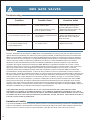
Standard Hydraulic Test Pressures
Hydraulic test to: BS 6755, EN 12266 - 1, EN 12266 - 2, DIN 3230 - 4, EN 1074 - 1, EN 1074 - 2
Working Pressure
Body Test Pressure
Seat Test Pressure
: 10 - 16 - 25
: PN 10 - 17 bar, PN 16 - 25 bar, PN 25 - 37,5 bar
: 1,1 times operating pressure
These instructions provide information about SMS gate valves. They are for use by personnel who are responsible
for installation, operation and maintenance of SMS gate valves.
All safety messages in the instructions are flagged with an exclamation symbol and the word Caution, Warning or
Danger. These messages must be followed exactly to avoid equipment damage, personal injury or death.
Safety label(s) on the product indicate hazards that can cause equipment damage, personal injury or death. If a
safety label becomes difficult to see, or if a label has been removed, please contact SMS for replacement label(s).
Handling and Unpacking Instructions
SMS gate valves have been packaged to provide protection during shipment, however, it can be
damaged in transport. Carefully inspect the valve for damage upon arrival and file a claim with the carrier if damage
is apparent.
Check the packing list against the valve received to verify that the quantities, sizes and materials are correct.
If the valve is to be stored before being installed, it should be protected from dirt, debris and corrosive materials
and should be kept in dry, dark and cool conditions, preferably indoors, out of direct sunlight. If outdoors storage is
unavoidable, support the valves off the ground and protect the valves with a watertight cover. Do not remove the
valve packaging, until necessary for inspection or installation.
Store the valve with the gate in the slightly closed position to protect the sealing edge.
Handling : Failure to lift the valve properly may cause damage. Lift the valve assembly with slings, chains or cables
fastened around the valve body. Lifting devices may be fastened to rods running through bolt holes in the flanges.
Do not fasten lifting devices to the gearbox or the actuator or the gate and never put any lifting devices through the
seat opening.
Take care in handling the valve not to damage the parts and painting of valve.
Installation
Carefully unpack the valve and inspect visually for damage during transport, handling and storage as this could
adversely affect valve performance.
Inspect the valve interior and rubber sealing. It should be clean, free from foreign matter or damage.
Be sure the line is depressurized and drained.
Be sure of the pipeline media. Proper care should be taken for protection against toxic and/or flammable fluids.
Check that the installation length between the pipe flanges is enough to position the valve without damaging.
Check the flange connection bolts-nuts and gaskets for proper size and length and be sure enough quantity.
Always be sure that the gate is in the full-closed position before installing the valve.
If practical, actuate the valve through close/open and open/close cycles to check the correct function.
Immediately prior to installation, check the flanges to which the valve is to be fastened. The flanges shall have a raised
face or a flat face. The sealing face shall be flat, without burrs, grooves, weld spatters, sharp edges and free from oil.
Check that the inside diameter of the flange or pipe bore is not too large as this will reduce the flange to valve sealing of
the gasket face.
Tighten the bolts in a crisscross fashion until the valve body (metal) touches the flange face.
Do not weld a connecting flange to the pipe with the valve installed in order to avoid overheating of the rubber sealing.
16