1
Designer’s Guide / Knight XL Boiler
LOCHINVAR CORPORATION
300 MADDOX SIMPSON PKWY
LEBANON, TN 37090
www.lochinvar.com
The purpose of System / Boiler Loop piping is to separate or “decouple” the system flow rate from
the boiler flow rate.
Reference Drawing A1 – Page 32.
Reference Drawing A1 – Page ??
The System Loop will have its own dedicated “System Circulator”. This circulator will circulate
throughout the building. The Boiler Loop will have its own dedicated “Boiler Circulator”. This
circulator will pull from the system to flow into and out of the boiler. The Boiler circulator is field
supplied and must be sized for the head loss of the boiler and related pipe and fittings in the
Boiler Loop only.
BOILER CIRCULATOR REQUIREMENTS
Again, there will be a minimum of two pumps in a System / Boiler Loop. Both pumps are
provided by the installer. The boiler pump must be sized to provide adequate flow through the
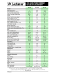
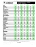
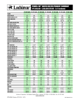
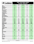
boiler and the Boiler Loop piping. A Boiler Temperature Rise Chart is provided to assist in proper
pump selection. This table provides GPM and boiler head-loss at various temperature rises for
each model based on Btu/hr input. Pipe diameter and length are critical to ensure proper flow
through the boiler. The values listed on the table are based on 20 feet of piping, 4 – 90° elbows
and 2 – full port ball valves.
CIRCULATOR PUMP SPECIFICATIONS
1. Maximum operating pressure for the pump must exceed system operating pressure.
2. Maximum water temperature should not exceed the nameplate rating.
3. Cast iron circulators may be used in closed loop systems.
18