1
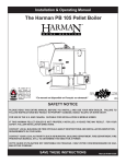
Installation & Operating Manual
Trident Boilers: SF160, SF260, SF360
Portland
“Ce manuel est disponible en Français sur demande”
R8
SAFETY NOTICE
PLEASE READ THIS ENTIRE MANUAL BEFORE YOU INSTALL AND/OR USE YOUR NEW
BOILER. FAILURE TO FOLLOW INSTRUCTIONS MAY RESULT IN PROPERTY DAMAGE,
BODILY INJURY, OR EVEN DEATH.
IF THIS HARMAN BOILER IS NOT PROPERLY INSTALLED, A HOUSE FIRE MAY RESULT. FOR
YOUR SAFETY, FOLLOW INSTALLATION DIRECTIONS.
CONTACT LOCAL BUILDING OR FIRE OFFICIALS ABOUT RESTRICTIONS AND INSTALLATION
INSPECTION REQUIREMENTS IN YOUR AREA.
Contact your local authority (such as municipal building department, fire
department, fire prevention bureau, etc.) to determine the need for a permit.
Save These Instructions
#3-90-70742
Introduction
Congratulations,
You have just purchased the finest wood / coal boiler available. Harman Trident boilers are constructed
of high quality materials and are manufactured by a highly skilled team of assemblymen. Each boiler is
inspected and pressure tested for quality assurance.
This manual is designed to provide all of the basic information needed for a safe and proper installation.
However, there are many skills needed that can not be learned by reading this manual. Harman Home
Heating recommends that the installation be performed by a plumbing and heating expert.
The Harman Trident Boilers are designed to operate safe, easy and automatically. You may however,
need to learn a few basic skills to maintain a fire. Especially if this is your first venture into solid fuel
burning. If you have any problems, re-read these instructions. If you can not resolve the issue(s),
Contact your Harman dealer.
Table Of Contents
3
Packing List
4
Installation
Aquastat
Wiring
Venting
Plumbing
5
6
7
7
8
Operating Instructions
Starting a Wood Fire
Starting a Coal Fire
Loading Fuel
Shaking Ashes
10
10
11
11
11
Safety Tips
12
Maintenance
13
Specifications
13
Warranty
14
Service Log
16
Service Parts
17
Packing List
Items needed for assembly and installation.
Please notify your Harman Dealer if you are missing any items.
Included with Boiler:
--Shaker Handle
--Ash Pan
--Warranty Registration Form
Items In Boiler Kit # 1-00-01020: (Sold Separately)
--Johnson Controls Aquastat - (3) pieces; A350 Controller w/ Sensor wire
S350 Stage Module
Y350 Power Supply
--Immersion Well
--Din Rail and (2) End Clamps
--Terminal Box
--Terminal Block and (2) #8-32 nuts
--Pressure Relief Valve (30 psi.)
--Temperature / Pressure Gauge
--Automatic Draft Control Assembly
--(1 pc.) Flex Conduit w/ (2) 90° Fittings w/ nuts, and (3) Chase Nipples w/ nuts
--(2) Manual Draft Control Knob Assembly
--(3) Brass Coil Spring Handle
Appliance Certification.
Model: Trident Series Boiler - SF160, SF260, &
SF360.
Test Lab: Omni-Test Laboratories, Inc.
Report #: 135-S-05-4
Type: Solid Fuel (Wood, Coal) Fired Appliance for
Residential Use
Standard(s): CAN/CSA B366.1-M87, and applicable
sections of UL 834 and ETLM 78.1
Note: This appliance is also approved for installation
into a shop.
4
Notice:
The Aquastat controls supplied with the
Boiler Kit are designed only to maintain
water temperature within the boiler.
The actual heating system is controlled
separately by your thermostat(s) opening
zone valves or energizing circulation
pump(s).
Do not attach a thermostat to the supplied
controls.
Installation
Getting Started
The sheet metal sides and top are easily removed
to reduce the chance of dents and/or scratches in
the finish. Simply lift the top off, and that will allow
the sides to be pulled away and up, for removal.
To re-install, slide the channel, at the bottom of
each side piece, over the lip at the bottom of the
boiler, and hold downward while moving the side
panel into place. Then slide the top down over the
sides.
NOTE: The sheet metal top holds the sides in
place, thus, no bolts or screws are needed.
Pressure Relief Valve
Domestic Hot Water
Coil Option
Temp/Pressure
Gauge
Immersion Well
Optional Electric
Back-up Elements
Johnson
Controls
Aquastat and
Terminal Block
Shaker Handle
Caution: Boiler should not
be installed closer than
36 inches (915 mm) to any
combustible material
Locating Boiler
Place the boiler as close to the chimney as
possible, while still maintaining the above
mentioned clearances. Bolt the shaker handle on
to the block on the side of the boiler, using the (2)
5/16 X 3/4 in. bolts and lock-washers.
FIG.1
Automatic Draft Control
Assembly
Install the Temperature/Pressure Gauge into the
pipe stub in the center of the round plate on the
front of the boiler (FIG. 1)
3/8 to 1/2 in.
Install the A350 sensor wire all the way into the
immersion well and screw the well into one of the
top hole
Turn the pressure relief valve into the stub on top
of the boiler, next to the supply outlet fitting.
NOTE: Use teflon tape to seal the threads
on all fittings. Any unused fittings must be
plugged
Bolt the two manual draft controls through the
holes in the top load door. (FIG.2) The draft control
knob should spin freely and open to a distance of
approximately 3/8 in. from the door surface, while
being able to close against the door surface.
5
FIG.2
Installation
Bolt the Automatic Draft Control through the 1/2
in. hole in the center of the bottom door. Be sure
to hold the Draft Control straight while tightening.
Feed the two wires from the draft motor through the
flexible conduit and a 90˚ fitting. Secure the fitting
to the draft motor and that end of the conduit at
this time. Check the flapper door on the Automatic
Draft Control assuring that it moves freely.
Install the (3) brass coil spring handles onto the
door latches and the shaker handle. Start the
spring handle onto the shaft and twist it counterclockwise while pushing.
Wiring Diagram
FIG.3
6
Aquastat Installation
(See optional items, page 7) Lay the din rail on
a flat surface, with the flat side down. Secure
one end clamp, on the left side. Slide the A350
controller onto the rail from right to left until it is
against the end clamp. Slide the Y350 onto the
rail and guide the plug-in connector, joining it to
the A350. Next, install the S350, again, guiding
the plug-in connector carefully. Install the other
end clamp to the right side of the din rail. Remove
the covers from all three controls by loosening
four screws each. Install the terminal box to the
controls using (3) chase nipples and locknuts,
supplied with the kit. Using the four holes in the
terminal box, mount the terminal box and controls
to the boiler sheet metal side as shown in Fig.1.
Using (2) #8-32 nuts, install the terminal block
onto the studs located inside the terminal box.
Installation
Wiring and Electrical
Optional Items
Following the wiring diagram, run all wires to their
designated connections. Save the main power for the
last hook-up, and leave the breaker in the off position.
The sensor wires attach to the A350 Controller on the
terminals marked “sen” and “com”. Make sure the
sensor is submerged fully into the well and secured
with the set-screws.
There is a domestic hot water coil available for your
Trident Boiler. The coil installs in the front of the boiler,
and allows your domestic water to be heated by the
heating system water. Install the coil now, by removing
the round plate and replacing it with the coil and it’s
round plate. Be sure to tighten the bolts evenly, to
ensure a good seal.
Setting The Aquastat
If electric back-up is desired, install now. There will be
two additional control boxes to add to your aquastat,
which will require the use of a longer din rail. The two
heating elements will install into the front of the boiler
as shown in Fig. 1
Inside the A350 control, you will see a square
jumper, and a differential dial. Be sure the jumper is
in the “Heating” position. The differential dial is set to
determine how low, below the temperature set point,
you want the water temperature to go before the
Automatic Draft Control opens. A good initial setting
for this dial is 5°. Be sure the 120V wires are attached
to the common and the normally open terminals, and
replace the cover. The external dial is set for the water
temperature you wish to maintain, a good setting is
180°.
Inside the Y350 control, ensure that your wires are
connected to the 120VAC terminals, and replace the
cover.
Inside the S350 control, which is used as overheat
protection, you’ll see two dials; offset, and differential.
There is also a jumper which, in this case, gets placed
in the “cooling” position. The offset dial sets the number
of degrees above the A350 setpoint that you want the
overheat dump to activate. A good set point would be
20°. That would mean that if the water reaches 200°,
using the A350 setpoint of 180°, the S350 would close
it’s contacts and energize the overheat dump zone.
The differential dial sets the point that the overheat
dump would stop. With the differential set at 15°, using
the temperatures above, the circuit would re-open,
stopping the overheat dump at a water temperature
of 185°. The 120V wiring is attached on the normally
open and the common position. The normally closed
position is not used.
Re-install the covers onto the three Controls.
7
FIG.4
Venting
The Harman Trident Boiler must be installed into a
chimney approved for solid fuel burning appliances.
In the U.S., the boiler must be connected to; (1) a
prefabricated chimney complying with the requirements
for Type HT chimneys in the Standard for Chimneys,
Factory Built, Residential Type and Building Heating
Appliances, UL 103. Or; (2) a code approved masonry
chimney with a flue liner. In Canada, with prefabricated
chimney systems tested and listed to the High
Temperature Chimney Standard ULC S-629, or with
a code approved masonry chimney. The minimum
recommended height for any chimney is 16 ft. (4.8m)
above the flue collar. Do not reduce flue diameter.
Nominal size flue is 8 X 8 in. or equivalent, up to 8
X 12 in. Codes also require that the chimney must
extend a minimum of
Installation
3 feet (0.9m) above the point at which they exit
from the roof, it must also extend 2 feet (0.6m)
above the highest point within a 10 ft. (3m) radius.
Do not connect this unit to a chimney
flue that is serving another appliance.
NOTE: The restriction of not venting more than one appliance to the
same flue applies to the U.S. specifically. In Canada, CSA B365-01
allows it, with specific restrictions. Be sure to contact your building
code inspection official to see if this option is allowed in your area,
and to find out the specific requirements for such an installation.
Plumbing
The Harman Trident Boiler can be used as a
“Stand Alone” boiler or as an add-on to an existing
hot water heating system.
The diagrams in this manual are meant to show
the necessary equipment and piping. Your system
may look very different. However, if configured
properly, the same results will be achieved.
Fig. 6 shows a typical plumbing diagram for tying
into an existing system. This method provides
water circulation between the two boilers with a
circulating pump. In this setup, the domestic water
coil in the existing boiler will be heated, making it
unnecessary to install a water coil in the Trident
Boiler.
Tying-in to an existing boiler must be done in the
return line between the circulator and the existing
boiler. Run a pipe from there to a small circulator,
and then into the 1-1/4 in. fitting on the rear of
the Trident Boiler. Next run a pipe from the 1-1/4
in. fitting on the top of the Trident Boiler to a Tee
fitting in the supply line of the existing boiler. This
Tee fitting must be installed between the existing
boiler and the Flow Control Valve, as shown in
Fig. 6. An air valve should be installed on this line.
FIG.5
Limit connector pipe to 8 ft. or less, with no more
than two elbows. All horizontal sections should
have 1/4 in. rise per foot. The chimney must be
capable of providing a draft reading of at least .06
in. of water column. A barometric damper can be
installed to prevent excessive and erratic draft.
All connector pipe should be secured with sheet
metal screws at each joint.
Air Valve
Notice:
The Aquastat controls supplied with the
Trident Boiler are designed only to maintain
water temperature within the boiler. The actual
heating system is controlled separately by
your thermostat(s) opening zone valves or
energizing circulation pump(s).
Do not attach a thermostat to the supplied
controls.
8
FIG.6
Installation
The circulator installed between the two boilers may be hooked up to run continuously during the
heating season or, an additional S350 control (not supplied) could be installed to turn it on and off
automatically. This control must be used as a “close on rise of temperature” (jumper in cooling position).
Harman Home Heating recommends that 1-1/4 in. pipe be used between the two boilers. Also
recommended is that the first section of pipe off of the top of the Trident Boiler be threaded galvanized
or threaded black-steel pipe.
The Harman Trident Boiler is supplied with a dual function aquastat. The A350 is used to control the
automatic draft control whether open, to increase heat, or closed, to decrease heat. The S350 is used
as overheat protection. Since a wood or coal fire is still producing heat when the draft is closed, this
overheat protection is required. You could have the S350 energize a circulating pump or a zone valve
separate from the heating system, or it could be hooked up so that it flows the heated water throughout
the system. Either way, it must be able to flow away from the boiler.
Figure 7 shows a typical schematic of the Trident boiler as a “stand alone” system. Note; the crossover
pipe (#12) is not totally necessary but is recommended to provide circulation within the boiler while the
heating system is satisfied. This will ensure an even temperature within the boiler. The tempering valve
shown (#10) is to prevent excessive temperature of the domestic water.
FIG.7
9
Operation
Automatic Draft Control
The heat output is regulated by the automatic
draft control on the bottom door. The electric
motor (A) opens and closes the flapper door (B).
Opening and closing the flapper door regulates
the air flow into the firebox.
The maximum air flow can be adjusted by turning
the adjusting bolt (C). Turn counter-clockwise for
more air, and clockwise for less air. Adjust this
bolt only while the flapper door is in the closed
position. Otherwise, motor damage could occur.
The idle air adjuster (D) controls the minimum
amount of air that enters the firebox. Adjustment
is made by turning the adjuster vertical for zero
idle air, or horizontal for maximum idle air. It is
best to start out with a medium setting as shown
in Figure 9.
FIG.8
Starting a Wood Fire
Make sure the boiler and all piping is full of water
and that all air has been purged from the system.
Never start a fire without water in the
system. An explosion will occur.
Turn on electrical power to the boiler. This should
cause the automatic draft control to open.
Open the ash pan door to allow free air
movement. With the firebox door open, crumble
approximately 8 sheets of newspaper and place
on the grates. Lay some small kindling on top of
the newspaper. Be sure this kindling is dry and no
more than 3/4 in. in diameter. Layer the kindling in
a criss-cross type pattern, to allow maximum air
flow. Next lay some larger pieces of wood on top of
the kindling (approximately 2 in. diameter). Using
a match or lighter, light the paper just inside the
door. Close and latch the firebox door and allow
the fire to burn a few minutes. After about five
minutes, close the ash pan door and re-open the
firebox door an inch or two, to allow the smoke to
clear. Add 4 or 5 larger logs (about 4 in. diameter)
to the well established fire and close the firebox
door. Leave the ash pan door open for about five
minutes only. Now open the firebox door using the
same method as before, always closing the ash
pan door before opening the firebox door. Now
you can load the firebox to the desired level. You
may load wood to the top of the firebox. Close and
latch the door. The ash pan door may again be
opened to speed the ignition process.
Do not leave the boiler unattended with any
door open.
After the wood is burning well, close the ash pan
door. The automatic draft control will now regulate
the fire, based on temperature demand.
The idle air adjuster must be tuned to where the
fire doesn’t go out during long periods with no
demand. Experience will dictate the best setting
for your installation. Normally, the two manual
draft controls on the firebox door are kept closed
while burning wood.
FIG.9
10
Operation
Starting a Coal Fire
Loading
Make sure the boiler and all piping is full of water
and that all air has been purged from the system.
Coal should never be added unless there is a
reasonably hot fire. The coal bed should be bright
and vigorous. If you have an active coal bed, full
loads can be added at any time. If not, add new
coal in layers, as described in starting a coal fire.
Never start a fire without water in the
system. An explosion will occur.
Turn on electrical power to the boiler. This should
cause the automatic draft control to open.
Open the ash pan door to allow free air movement.
Use the same procedure as starting a wood fire
except, do not load the larger diameter wood Use
wood about 2 in. diameter maximum. This size will
form a very hot charcoal bed in less time. Again,
the ash pan door may be opened periodically to
speed the ignition process.
Do not leave the boiler unattended
with any door open.
When you have accumulated a substantial
charcoal bed, start adding a thin layer of coal. Pea
or Nut sized coal is better for starting than Stove
coal.
When the first layer is burning with some blue
flame, continue to add thin layers of coal until
there is a solid bed of burning coal. Let each layer
burn a blue flame before adding another layer.
Additional coal can be layered in until the bed is
approximately 10 inches deep. By now, you should
have the ash pan door closed, and the automatic
draft control will continue to regulate the fire.
The idle air adjuster may need to be set for slightly
less air for coal than wood. Here again, experience
will dictate the best setting. The maximum air bolt
can be turned all the way “counter-clockwise” to
allow for a quicker recovery. Never adjust this bolt
with the flapper open.
The two manual draft controls, on the firebox
door, are used to allow secondary air to pass
over the fire when burning coal. This helps to
burn the gasses that are emitted from the coal as
it is heated. Your setting for these draft controls
should be between 1/2 and 1 complete turn from
closed. Adjust both controls equally.
11
Shaking the Grates
Shaking should be done only when there is a
well-established fire. The frequency of shaking
will depend on the degree of burning. Twice a day
shaking is recommended. The best results are
achieved with short, choppy strokes as opposed
to long, even strokes. Full rocking of the grates
may allow burning coal to fall into the ash pan.
The amount of shaking is critical, too much can
disrupt the fire bed, and too little will restrict airflow. The proper amount of shaking is normally
achieved when hot red coals first start to drop
through the grates into the ash pan.
Every effort should be made to not let a coal fire
burn down too low. This will cause the reloading
process to be much longer, with a real good
chance of losing the fire altogether.
Do not shake or stir with a low fire. Open the
ash pan door to get maximum air flowing into the
firebox. Once burning is restored, close the ash
pan door and add a layer of coal to the fire bed.
Follow the instructions under Starting a Coal Fire.
When the new coal is thoroughly ignited, and
there is a substantial bed of hot coals, the grates
may then be shaken.
Ashes and Ash Removal
Ashes should never be allowed to accumulate
above the top of the ash pan. Ashes in contact
with the bottom of the grates act as insulation,
which intensifies the heat on the grates and
causes them to sag or warp. Also, too much ash
accumulation will restrict air-flow which will make
fire maintenance more difficult. Place ashes in
a sealed metal container, outside, until they are
cooled enough for final disposal. Coal produces
considerably more ash than wood, so the intervals
between emptying are much shorter.
Operation
Safety Tips
When opening the firebox door, it should be
cracked, slightly open, for a few seconds to allow
air in to burn any gases which may be present.
This will also allow smoke to be drawn away from
the door. Whenever the ash pan door is open, it
should be closed before opening the firebox door.
The firebox should never be filled with excessive
coal to where the flue exit is blocked or impeded
in any way.
Burning coal produces Carbon Monoxide. If
the flue exit is blocked, the Carbon Monoxide
can be forced out of the boiler, into the room,
with possible FATAL consequences.
With the exception of start-up or freshening of
the fire, or performing ash removal, the ash pan
door should be kept closed.
Never install a Harman Trident Boiler into a
chimney with a history of down-drafts.
Keep Children Away - May Cause
Serious Burns.
CAUTION: All surfaces of the boiler are
hot. Do not touch. Keep children away.
Serious burns will result if touched.
This is a heat producing appliance.
DANGER: Fire Hazard, Do not use
chemicals or flammable liquids to start
or “freshen-up” a fire. Severe burns
or a house fire may result. Do not
burn Garbage, Gasoline, Thinners, Oil,
Kerosene Etc. An explosion, a house
fire or serious personal injury could
result. Keep all such liquids well away
from this boiler.
12
During the first few hours of burning, a blue
smoke may be observed rising from the boiler.
This is the paint going through the curing process.
It is advisable to increase the amount of fresh
air in the room during this break in period. This
can be achieved by opening doors and windows.
Don’t be alarmed, this is normal and will only last
a short while.
Chimney Problems
Not Enough Draft - Chimney is too low. The
general rule for chimneys is 16 feet tall, and two
feet higher than anything ten feet around it.
Air may be leaking in around a loose fitting cleanout door.
Too many elbows in connector pipe, or seams and
joints of connector pipe are not secured properly.
Improperly sized chimney or stovepipe.
Chimney may be blocked with creosote or bird
nests or similar obstructions.
Cracked or defective chimney flue or liner.
Down Drafts - Trees or other topographical
barriers may impede on chimney performance
causing air currents to be pushed downward into
the flue. This can also be caused by neighboring
buildings or other chimneys.
Creosote and condensation - If creosote
or condensation runs out of the chimney or stove
pipe, check the following; Chimney cap or liner
may be defective, Boiler may be positioned too
far away from the chimney which would not allow
the chimney to warm, Wood being burned may
be green or wet, Boiler may be over-sized for the
residence causing it to be burned on low too often.
Excessive Draft - This can be controlled with
a barometric damper in the stove pipe.
Maintenance
The spiral chamber is basically self-cleaning. However, if there is a draft problem and you have been
burning wood for a long time with little demand, the spiral chamber will need to be cleaned. To clean the
spiral chamber, remove the stovepipe and scrape any creosote or debris from the top and front of the
chamber. The rear of the chamber should not have much accumulation. If it does, clean it out.
NOTE: 1/4” to 1/2” of creosote in the spiral chamber is normal.
The pipes inside the firebox will accumulate creosote if the demand for heat is too low, when burning
wood. 1/8” to 1/4” of creosote is normal on the pipes and firebox walls. If more creosote has accumulated,
it should be scraped off of these surfaces.
NOTE: Creosote in the firebox can be burned off by burning coal for a few days.
The fire bricks may become cracked during the course of normal operation. A cracked brick that is still
in place, is still doing its job, and need not be replaced immediately. If a brick is broken, and has fallen
out of place, it should be replaced before any further burning occurs. The firebricks used in the Trident
Boiler are available for replacement from your Harman dealer.
Gaskets on the doors are there to regulate air to the firebox. If a gasket is failing, you’ll notice difficulty
in controlling the fire. Inspect the gaskets regularly, and replace with Harman supplied material only.
13
Specifications
SF-160
SF-260
SF-360
Heating Capacity (Square Feet)
2200 Max.
3200 Max.
4500 Max.
Approximate BTU per hour (wood or coal)
90,000
130,000
180,000
AMP Rating
40
40
40
Water Capacity (US Gallon)
25
32
42
Weight
640 Lbs
780 Lbs
925 Lbs
Hydro-Pressure Tested
Yes
Yes
Yes
Firebox Dimensions (inches)
16W x 22L x 19H
18W x 26L x 20H
18W x 30L x 25H
Recommended Log Length (inches)
19
23
27
Door Opening Size (inches)
11 x 13
13 x 13
13 x 13
Overall Dimensions (inches)
23W x 23.5L x 45H
26W x 27.5L x 45.5H
26W x 31.5L x 51.5H
Flue Size (diameter)
6 inch
7 inch
7 inch
Flue Height (top of flue)
37.5 inches
38.75 inches
44 inches
Number Of Grates (10 Lbs. Each)
4
5
6
Type Of Fuel
Coal / Wood
Coal / Wood
Coal / Wood
Water Inlet and Outlet Size
1.25 NPT
1.25 NPT
1.25 NPT
Automatic Draft Control
Yes
Yes
Yes
Aquastat
Yes
Yes
Yes
Temperature / Pressure Gauge
Yes
Yes
Yes
ASME Pressure Relief Valve
Yes
Yes
Yes
Ash Pan With Handle
Yes
Yes
Yes
Domestic Hot Water Coil (optional)
4 GPM
4 GPM
4 GPM
Approximate BTU per hour (electric option)
30,000
30,000
30,000
Kilowatt Rating (electric option)
9
9
9
Warranty
HARMAN™ CENTRAL HEATING PRODUCTS LIMITED WARRANTY
Hearth & Home Technologies Inc., on behalf of its Harman™ brand (”HHT”), extends the following warranty for all
Harman™ furnace and boiler products (“Products”) that are purchased from an HHT authorized dealer.
Warranty Coverage: Subject to the conditions, exclusions and limitations set forth below, HHT warrants to the original
owner of the Products, and to any transferee taking ownership of the Products at the site of original installation within two
years following the date of original purchase, that the Products will operate free from defects in material and workmanship
under normal conditions and use, as described in the operating instructions furnished with the Product, during the warranty
period described below. HHT will, at its option, repair or replace any Product covered by this warranty that is determined to
be defective in material or workmanship.
Warranty Period: The warranty period runs for six years, except for mechanical and electrical components, which are
warranted for three years. The warranty period begins on the earlier of: (i) the date of invoice for the Product; (ii) in the case
of new home construction, the date of first occupancy of the residence or six months after the date of sale of the Product by
an HHT authorized dealer, whichever occurs first; or (iii) the date 24 months following the date of Product shipment from
HHT, regardless of the invoice or occupancy date.
Warranty Conditions: This warranty applies only to Products: (i) installed, operated, and maintained as recommended in
the Product user’s manual; (ii) purchased through an HHT authorized dealer; (iii) while remaining at the site of original
installation; and (iv) that have not been altered after leaving the factory.
How to File a Claim: Claims must be made within the warranty period to the dealer who sold the Product. If that dealer
cannot provide the warranty service, contact the nearest HHT authorized dealer. Additional service fees may apply if you
are seeking warranty service from a dealer other than the dealer from whom you originally purchased the Product. Travel
and shipping charges for parts are not covered by this warranty.
Warranty Exclusions: This warranty does not cover the following: (1) consumable and normal wear items, including,
without limitation, flame guides, grates, coal bars, afterburner hoods, fire brick, gaskets, paint, glass discoloration, burnpot
housing weldments, burnpot grate weldments (pellet or corn), burnpot front plates (pellet or corn), burnpot front plate
locks, corn auger extensions, ceramic inserts, and ceramic insert plates; (2) noise caused by minor expansion, contraction
or movement of parts; (3) damage resulting from: (i) failure to install, operate or maintain the Product according to the
installation and operating instructions and listing agent identification label furnished with the Product; (ii) failure to install
the Product according to local building codes; (iii) shipping or improper handling; (iv) abuse, misuse, continued operation
with damaged, corroded or failed components, accident, or incorrectly performed repairs; (v) environmental conditions,
inadequate ventilation, negative pressure or drafting caused by tightly sealed construction, insufficient make-up air supply,
or handling devices such as exhaust fans or forced air furnaces or other such causes; (vi) use of fuels other than those
specified in the operating instructions; (vii) installation or use of components or accessories not supplied with the Product
or authorized and approved in writing by HHT; (viii) modification of the product not expressly authorized and approved by
HHT in writing; or (ix) interruptions or fluctuations of electrical power supply to the Product; (4) non-HHT components
or accessories used in conjunction with the Product; (5) the Products’ capability to heat a desired space; information is
provided to assist the consumer and the dealer in selecting the proper Product for the application; consideration must be
given to Product location and configuration, environmental conditions, insulation and air tightness of the structure; or (6)
additional or unusual utility bills incurred due to any malfunction or defect in Products.
Limitations of Liability: Repair or replacement in accordance with the provisions of this warranty will be the owner’s
exclusive remedy for and will constitute HHT’s sole obligation under this warranty, under any other warranty (express or
implied), or in contract, tort or otherwise. No employee, agent, dealer, or other person is authorized to give any warranty
on behalf of HHT. TO THE EXTENT ALLOWED BY LAW, HHT MAKES NO OTHER WARRANTY, EXPRESS
OR IMPLIED, INCLUDING ANY WARRANTY OF MERCHANTABILITY OR FITNESS FOR A PARTICULAR
PURPOSE. HHT WILL NOT BE LIABLE FOR ANY CONSEQUENTIAL OR INCIDENTAL DAMAGES ARISING
OUT OF DEFECTS IN OR USE OF THE PRODUCTS. Some states do not allow exclusions or limitation of incidental or
consequential damages, so these limitations may not apply to you. This warranty gives you specific rights; you also may
have other rights, which vary from state to state. The duration of any implied warranty is limited to the duration of the
warranty period specified herein.
14
Notes
Notes
15
15
Service & Maintenance Log
Date Of Service
16
Performed By
Description Of Service
SF160
Service Parts
Wood, Coal fired Boiler
Beginning Manufacturing Date: N/A
Ending Manufacturing Date: Active
1-70-03233
11
1
2
3
4
8
9
10
5
6
7
IMPORTanT: THIS IS DaTED InFORMaTIOn. When requesting service or replacement
parts for your appliance please provide model number and serial number. all parts listed
in this manual may be ordered from an authorized dealer.
ITEM
DESCRIPTION
COMMENTS
Stocked
at Depot
PART NUMBER
1
Safety Relief Valve
3-10-77382
Y
2
Press/temp Gauge-Rear Mount
3-10-78427
Y
3
aquastat Sensor Well
3-10-935111
Y
4
Stove Water Plate (6 holes, 1 fitting)
Post 1199
1-10-08024
3-10-24758
Y
Qty 2 req
4-00-00042
Y
4 Sets
1-00-00036
Y
4-00-00197P
Y
Gasket, Boiler Plate
5
Door Handle - Cast
Door latch
load Door - Cast
Draft Control Knob - Cast
Qty 2 req
4-00-00109-1
additional service parts on following page.
06/12
SF160
Service Parts
Beginning Manufacturing Date: N/A
Ending Manufacturing Date: Active
IMPORTanT: THIS IS DaTED InFORMaTIOn. When requesting service or replacement
parts for your appliance please provide model number and serial number. all parts listed
in this manual may be ordered from an authorized dealer.
ITEM
6
7
8
DESCRIPTION
COMMENTS
Stocked
at Depot
PART NUMBER
1-10-01005
Y
Shaker Bar Weldment 4-1/4”
1-10-02017W
Y
Shaker Block
2-00-01037-1
Y
Shaker Bracket
2-00-01047B
Shaker Handle Mount
2-00-01037-2
Y
1-10-03375
Y
Draft Motor 120v
3-20-45338
Y
Draft Motor Mount Bracket
2-00-01010B
ash Door - Cast
4-00-00200-1D
long Shaker Handle Weldment
automatic Draft Control assembly
Pre 1199
1-00-03500
Y
Controller a350aa-2C
Post 1199
3-10-1350112
Y
aquastat Termianl block
Post 1199
1-10-03501a
Power Supply Y350R-1C
Post 1199
3-10-935071
Y
Stage Module S350aa-1C
Post 1199
3-10-7350111
Y
aquastat Replacement for White Rogers
9
Side Jacket w/Hole
2-00-00315-15S
10
Side Jacket without Hole
2-00-04124-15S
11
Jacket Top
aquastat Sensor/a350 Control aPPBC-25C
2-00-08128-15S
Post 1199
ash Pan
Boiler Electric Back-up for Johnson Controls
Post 1199
3-10-2992225
Y
1-10-16027
Y
1-00-01019
Boiler Kit assembly
1-00-01020
Domestic Coil assembly
1-00-07006
Domestic Coil Water Plate (8 holes, 1 fitting, 2 nuts)
1-10-07006
Gasket 1/2” Rope (load Door & ash Door)
20 Ft
1-00-53500
Y
Grate 13 in - Cast
Qty 4 req
3-00-00207
Y
Grate Holder - Cast
Qty 4 req
3-00-00193
Y
Grate link - Cast
4-00-00205D
Y
non-electric Boiler Kit (includes regulator & draft control)
1-00-08012
Draft Regulator Type C-20 (use with non-electric kit)
3-91-05000
non-electric Draft Control assembly
Standard Brick 9” x 4-1/2” x 1-1/4” (6 needed)
Brick angles
1-10-08013a
Pkg of 7
1-00-900450125
Pkg of 4
1-00-01138
4.5 oz Can
3-42-7727
Set of cut brick
Touch Up Paint
Y
1-00-08124
Y
Y
06/12
SF260
Service Parts
Beginning Manufacturing Date: N/A
Ending Manufacturing Date: Active
Wood, Coal fired Boiler Appliance
1-70-03236
10
1
2
3
7
8
9
4
5
6
IMPORTanT: THIS IS DaTED InFORMaTIOn. When requesting service or replacement
parts for your appliance please provide model number and serial number. all parts listed
in this manual may be ordered from an authorized dealer.
ITEM
DESCRIPTION
COMMENTS
PART NUMBER
Stocked
at Depot
Safety Relief Valve
3-10-77382
Y
2
Press/temp Gauge-Rear Mount
3-10-78427
Y
3
Stove Water Plate (6 holes, 1 fitting)
1-10-08024
1
3-10-24758
Y
Qty 2 req
4-00-00042
Y
Door latch
4 Sets
1-00-00036
Y
Draft Control Knob - Cast
Qty 2 req
4-00-00109-1
Gasket, Boiler Plate
4
Door Handle - Cast
load Door - Cast
Flapper Weldment 17-1/2”
4-00-00195P
1-10-00407
additional service parts on following page.
06/12
SF260
Service Parts
Beginning Manufacturing Date: N/A
Ending Manufacturing Date: Active
IMPORTanT: THIS IS DaTED InFORMaTIOn. When requesting service or replacement
parts for your appliance please provide model number and serial number. all parts listed
in this manual may be ordered from an authorized dealer.
ITEM
5
6
7
DESCRIPTION
COMMENTS
Stocked
at Depot
PART NUMBER
1-10-01005
Y
Shaker Bar Weldment 4-11/16”
1-10-02018W
Y
Shaker Block
2-00-01037-1
Y
long Shaker Handle Weldment
Shaker Bracket
2-00-01047B
Shaker Handle Mount
2-00-01037-2
Y
1-10-03375
Y
automatic Draft Control assembly
Draft Motor Mount Bracket
2-00-01010B
ash Door - Cast
4-00-00200-1D
Draft Motor 120v
3-20-45338
Y
Pre 1199
1-00-03500
Y
aquastat Sensor/a350 Control a99BC-25C
Post 1199
3-10-2992225
Y
auastat Terminal Block
Post 1199
1-10-03501a
aquastat Sensor Well
Post 1199
3-10-935111
Y
Controller a350aa-2C
Post 1199
3-10-1350112
Y
Power Supply Y350R-1C
Post 1199
3-10-935071
Y
Stage Module S350aa-1C
Post 1199
3-10-7350111
Y
aquastat Replacement for White Rodgers
8
Side Jaccket w/Hole
2-00-00327-15S
9
Side Jacket without Hole
2-00-07002-15S
10
Top Jacket
2-00-08132-15S
ash Pan
Boiler Electric Back-up for Johnson Controls (option)
1-10-25027
Post 1199
Y
1-00-01019
Domestic Boiler Coil assembly
1-00-07006
Boiler Kit assembly
1-00-01020
Domestic Coil Water Plate (8 holes, 1 fitting, 2 nuts)
1-10-07006
Gasket, 1/2” Rope (load Door & ash Dppr)
20 Ft
1-00-53500
Y
Grate Holder 2 - Cast
Qty 2 req
3-00-00193
Y
Grate Holder 3 - Cast
Qty 2 req
3-00-00194
Y
3-00-00205
Y
3-00-00208
Y
Grate link 5 - cast
Grate 15 in - Cast
Qty 5 req
non-electric Boiler Kit (includes regulator & draft control)
1-00-08012
Draft Regulator Type C-20 (use with non-electric kit)
3-91-05000
non-electric Draft Control assembly
Standard Brick 9” x 4-1/2” x 1-1/4” (8 needed)
1-10-08013a
Pkg of 7
1-00-900450125
Brick angles
1-00-01138
Set of cut Brick
1-00-00842
Touchup Paint
Y
Y
Y
3-42-7737
06/12
SF360
Service Parts
Beginning Manufacturing Date: N/A
Ending Manufacturing Date: Active
Wood, Coal Fired Boiler
1-70-03239
10
1
2
3
7
8
9
4
5
6
IMPORTanT: THIS IS DaTED InFORMaTIOn. When requesting service or replacement
parts for your appliance please provide model number and serial number. all parts listed
in this manual may be ordered from an authorized dealer.
ITEM
DESCRIPTION
COMMENTS
Stocked
at Depot
PART NUMBER
1
Safety Relief Valve
3-10-77382
Y
2
Press/temp Gauge-Rear Mount
3-10-78427
Y
3
Stove Water Plate (6 holes, 1 fitting)
1-10-08024
3-10-24758
Y
Qty 2 req
4-00-00042
Y
Door latch
4 Sets
1-00-00036
Y
Draft Control Knob - Cast
Qty 2 req
4-00-00109-1
Gasket, Boiler Plate
4
Door Handle - Cast
load Door - Cast
Flapper Weldment 17-1/2”
4-00-00195P
1-10-00407
additional service parts on following page.
06/12
SF360
Service Parts
Beginning Manufacturing Date: N/A
Ending Manufacturing Date: Active
IMPORTanT: THIS IS DaTED InFORMaTIOn. When requesting service or replacement
parts for your appliance please provide model number and serial number. all parts listed
in this manual may be ordered from an authorized dealer.
ITEM
5
6
7
DESCRIPTION
COMMENTS
Stocked
at Depot
PART NUMBER
1-10-01005
Y
Shaker Bar Weldment 4-11/16”
1-10-02018W
Y
Y
long Shaker Handle Weldment
Shaker Block
2-00-01037-1
Shaker Bracket
2-00-01047B
Shaker Handle Mount
2-00-01037-2
Y
1-10-03375
Y
automatic Draft Control assembly
ash Door - Cast
4-00-00200-1D
Draft Motor Mount Bracket
2-00-01010B
Draft Motor 120v
3-20-45338
Y
Pre 1199
1-00-03500
Y
aquastat Sensor/a350 Control aPPBC-25C
Post 1199
3-10-2992225
Y
aquastat Terminal Block
Post 1199
1-10-03501a
aquastat Sensor Well
Post 1199
3-10-935111
Y
Controller a350aa-2C
Post 1199
3-10-1350112
Y
Power Supply Y350R-1C
Post 1199
3-10-935071
Y
Stage Module S350aa-1C
Post 1199
3-10-7350111
Y
aquastat Replacement for White Rodgers
8
Side Jacket w/Hole
2-00-01516-15S
9
Side Jacket without Hole
2-00-05121-15S
10
Top Jacket
2-00-08129-15S
ash Pan
1-10-35027
Domestic Coil assembly
1-00-07006
Boiler Electric Back-up for Johnson Controls
Post 1199
1-00-01019
Boiler Kit assembly
1-00-01020
Domestic Coil Water Plate (8 holes, 1 fitting, 2 nuts)
1-10-07006
Gasket 1/2” Rope (load Door & ash Door)
20 Ft
Grate Holder 3 - Cast
Qty 4 req
Grate link 6 - Cast
Grate 15 in - Cast
Qty. 6 req.
1-00-53500
3-00-00194
Y
Y
3-00-00208
Y
1-00-08012
Draft Regulator Type C-20 (use with non-electric kit)
3-91-05000
Standard Brick 9” x 4-1/2” x 1-1/4” (20 needed)
Brick angles, Pkg of 4
Touchup Paint
Y
3-00-00206
non-electric Boiler Kit (includes regulator & draft control)
non-electric Draft Control assembly
Y
Y
1-10-08013a
Pkg of 7
Qty 2 req
1-00-900450125
Y
1-00-01138
3-42-7737
06/12
At Harman, we build each product to a standard, not a price.
(Signature of Boxer)
Your premium quality hearth product designed and assembled
by the experienced and skilled members at Harman in Halifax,
PA, USA.
Proudly Printed On 100% Recycled Paper


![Terms of Reference [ 462 KB]](http://vs1.manualzilla.com/store/data/005818895_1-55ed04ecdfa99aee80736235a8d4f256-150x150.png)